Page 145 of 284
METERS AND GAUGES-Specifications /Troubleshooting 8425
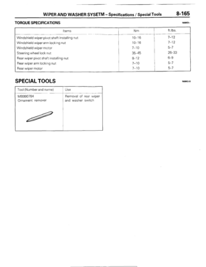
TORQUE SPECIFICATIONS
Items Nm ft.lbs.
Water temperature gauge unit 8-10 6-7
SEALANTS AND ADHESIVES
Items
Water temperature gauge unit threaded portion Specified sealants and adhesives
3M nut locking No. 4171 or equivalent Quantity
As required
TROUBLESHOOTING
TACHOMETER NOBHH-
Inspection items
Symptom
The tachometer fails to operate
I The tachometer pointer is faulty
NOTE
Number in circle indicates inspection sequence.
FUEL GAUGE
Inspection items
Symptom
The fuel gauge fails to operate
The fuel gauge pointer is faulty
NOTE
Number in circle indicates inspection sequence.
1 STB Revision
Page 146 of 284
8-126 METERS AND GAUGES -Troubleshooting
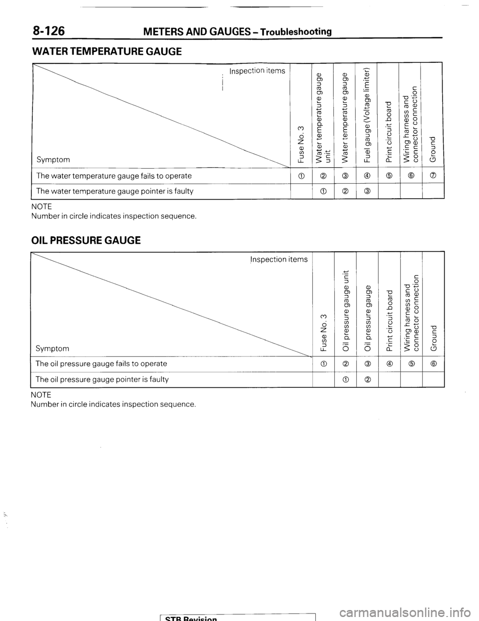
WATER TEMPERATURE GAUGE
Symptom
The water temperature gauge fails to operate
-0
c
2
(5
a 0 0
0 a
I The water temperature gauge pointer is faulty a NOTE
Number in circle indicates inspection sequence.
OIL PRESSURE GAUGE jnspection items
Symptom
0
0
a The oil pressure gauge fails to operate
The oil pressure gauge pointer is faulty
NOTE
Number in circle indicates inspection sequence
( STB Revision
-IIII
Page 147 of 284
METERS AND GAUGES -Troubleshooting 8-127
BRAKE WARNING LIGHT
Inspection items
Other inspection
items
Symptom
When the ignition key is at ON (without starting the
engine) the indicator fails to illuminate
Starting the engine does not make the indicator go
off (when the parking brake is not engaged) t 0 0
c
The indicator does not illuminate when the parking
brake is on, when the brake fluid falls below the
regulation volume
a a Co
NOTE
Number in circle indicates inspection sequence.
EGR WARNING LIGHT
U
5
P
W
0
Co When the ignition key is at ON (without starting the engine) the indicator
fails to illuminate
0 The EGR warning indicator fails to illuminate after the car has travelled
every 50,000 miles (Light bulb is OK.)
Even when the reset switch is turned over the light does not go off 0 0
0
I
NOTE
Number in circle indicates inspection sequence.
[ STB Revision
Page 148 of 284
8-128 METERS AND GAUGES - Circuit Diagram
CIRCUIT DIAGRAM
METER CIRCUIT
Ignition switch
q [Refer to
To turn-signal switch
[Refer to P.8-491
I
To seat belt timer
[Refer to P.8-661 P.8-511 -
To seat belt warning
buzzer [Refer to P.8-661
1.25-GBA
, ^.
To alternator 48,5!W III -1 / 1 , 1 '----f--d+ii$$j IRefer to P.8.371 D I
.I_ -0 dimmkr, passinq
‘I+,:’ ! I I I II -I
I r I I I II YI
;witch and light control y K
clay [Refer to P.8-461
To dome liaht 5--hIIII I
----m-w-
[Refer to P&47] -w
Combination meter
( STB Revision
Page 149 of 284
METERS AND GAUGES - Circuit Diagram 8-129
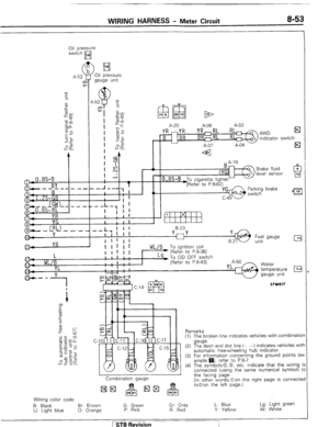
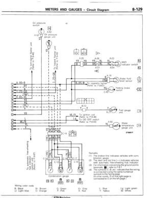
011 pressure
switch YB
H I
>
A-52
Oil pressure
gauge unit
(
A-52
UY
>
-0.85-B
r.., !
YB
A-20 A-06 A-03
YR mYR YR,RL RL 4WD El B indicator switch
-- L7 I I 1 8-23
I I I I I
I 1 !
Fuel 1 1 gauge
unit
L
WL/B
YL
g-- y
1
I
I I I I I I LY)T~ OD OFF switch
1 1 I
I ' ; [Refer to P.8-431 I I
I . . I
'4 8.
Combination gauge
Wiring color code
6: Black Br: Brown G: Green Gr: Gray
LI: Light blue 0: Orange P: Pink
R: Red
Y Water
temperature
gauge unit
Remarks
(I) The broken line indicates vehicles with com-
bination gauge.
(2) The dash and dot line (-.-) indicates vehicles
with automatic free-wheeling hub indicator.
(3) For information concerning the ground points
(example: 0 ). refer to P.8-7.
(4) The symbols @I,@, etc. indicate that the wiring
is connected (using the same numerical
symbol) to the facing page.
(In other words, 0 on the right page is
connected to 0 on the left page.)
L: Blue
Y: Yellow Lg: Light green
W: White
/ STB Revision
Page 150 of 284

8430 METERS AND GAUGES - Service Adjustment Procedures.
SERVICE BJUSTMENT. PROCEDURES
SPEEDOMETER INSPECTION NOSHIAA
I. Adjust tire inflation pressure to the standard value. (Refer
to’GROUP 22 WHEELS AND TIRES-General Specifications)
2. Use speedometer tester to make sure that the speedome-
ter indication error is within the standard value.
Standard value :
Meter with “km/h” indication km/h
20 km/h +4
-1
40 km/h +4
0
80 km/h +5
0
120 km/h + 5.5
+0.5
Meter with “mph” indication
mph
10 mph
25 mph
50 mph
75 mph +I.5
21.5
+I.5
&I.5
Caution
1 When using a speedometer tester to inspect the
speedometer, be sure to chock the non-drive wheels
to prevent the vehicle from moving. Also be sure to
set the transfer shift lever to “2H”.
2 If there is a special regulation for speedometer
indication error in the area where the ‘vehicle is
operated, be sure to meet the requirement of the
regulation.
TACHOMETER INSPECTION NOBHIBA
Connect a tach-dwell meter, and then compare the meter
readings at various engine speeds with the values indicated on
the tachometer.
Standard value:
1,000 r/min
3,000 r/min
5,000 r/min f 100 r/min
2150 r/min
&250 r/min
Tgch-dwell meter Caution
The tachometer is the negative-ground type, and therefore
should not be connected in reverse polarity to the battery.
If the tachometer is connected in reverse polarity, the
transistors and diodes will be damaged.
evision
Page 151 of 284

METERS AND GAUGES - Service Adiustment Procedures 8-131
r
(harness side) 16W834
Stopper (upper)
FUEL GAUGE SIMPLE TEST NOEHICE
(1) Disconnect, from below the vehicle, the wiring connector
from the fuel gauge unit.
(2) Ground the connector at the harness through a test light.
(3) Turn the ignition key to the ON position.
(4) Check to be
sure that the test light flashes and the fuel
gauge indicator moves.
(5) If both the test light and gauge operate, the circuit to the
gauge unit is normal and the gauge unit itself is faulty.
If the test light flashes but the gauge does not operate, the
gauge is faulty.
If neither the test light nor the gauge operates, the fuel
gauge circuit is faulty.
FUEL GAUGE UNIT INSPECTION NOEHIIF
To check the fuel gauge unit, first remove it from the fuel tank.
For detailed information concerning installation of the fuel
gauge unit, refer to GROUP 4, FUEL SYSTEM - Fuel Tank.
FUEL GAUGE UNIT FLOAT POSITION CHECK
Check to be sure that the height of the fuel gauge float
(relative to the center part of the fuel gauge unit) is within the
standard value range when the float is at the “F” position
(upper limit) and “E” position (lower limit).
Standard value:
A 29.7-34.7 mm (1.170-I .366 in.)
B 183.8-185.8 mm (7.236-7.315 in.)
FUEL GA&E UNIT RESISTANCE CHECK
Confirm that the resistances when the float of the fuel gauge
unit is at the “F” position (top) and the “E” position (bottom)
are within the standard value ranges.
Standard value:
Float position “F” point 14.9-19.1 IR c
Float position “E” point 113.5-126.5 IR’
WATER TEMPERATURE GAUGE SIMPLE T,5$2
(1) Disconnect the wiring connector from the water tempera-
ture gauge unit inside the engine compartment.
(2) Ground the connector at the harness through a test light.
(3) Turn the ignition key to the ON position.
(4) Check to be sure that the test light flashes and the water
temperature gauge indicator moves. ,
1 STB Revision
Page 152 of 284

8-132 METERS AND GAUGES - Service Adjustment Procedures
(5) If both the test light and gauge operate, the circuit to the
gauge unit is normal and the gauge unit itself is faulty.
If the test light flashes but the gauge does not operate, the
gauge is faulty.
If 1 neither the test light nor the gauge operates, the water
temperature gauge circuit is faulty.
Se
VVATER TEMPERATURE GAUGE UNIT ONSPEC-
TION
NOBHIKD
To check the water temperature gauge unit, first remove it
from the intake manifold.
For detailed information concerning installation of the water
temperature gauge unit, refer to GROUP 11, INTAKE AND
EXHAUST SYSTEM - Intake Manifold.
WATER TEMPERATURE GAUGE UNIT RESISTANCE CHECK
Immerse the gauge unit in hot water at 70°C (158°F) and
measure the resistance value with an ohmmeter.
Standard value: 90.5 - 117.5 LR
OIL PRESSURE GAUGE SIMPLE TEST NOEHIFA
(1) Disconnect the wiring connector from the oil pressure
gauge unit inside the engine compartment.
(2) Ground the connector at the harness through a test light.
(3) Turn the ignition key to the ON position.
(4) Check to be sure that the test light illuminates steadily and
the indicator of the oil pressure gauge moves.
(5) If both the test light and gauge operate, the circuit to the
gauge unit is normal and the gauge unit itself is faulty.
If the test light flashes but the gauge does not operate, the
gauge is faulty.
If neither the test light nor the gauge operates, the oil
pressure gauge circuit is faulty.
1 STB Revision
-7