1987 MITSUBISHI MONTERO check oil
[x] Cancel search: check oilPage 8 of 284

8 INTRODUCTION - Precautions Before Service
r oorn,
FOOOl;
FOOOl8
PRECAUTIONS BEFORE SERVICE
PROTECTIN” THE VEHICLE NOODAAC
If theIre is a likelihood of damaging painted or interior parts
during service operations, protect them with suitable covers
(such as seat covers. fender covers, etc.).
REMOVAL AND DISASSEMBLY
When checking a malfunction, find the cause of the problem.
If it is determined that removal and/or disassembly is neces-
sary, perform the work by following the procedures contained
in this, Workshop Manual.
If punch marks or mating marks are made to avoid error in
assembly and facilitate the assembly work, be sure to make
them in locations which will have no detrimental effect on
performance and/or appearances.
If an area having many parts, similar parts, and/or parts which
are’ symmetrical right and left is disassembled, be sure to
arrange the parts so that they do not become mixed during the
assembly process.
1. Arrange the parts removed in the proper order.
2. Determine which parts are to be reused and which are to
be replaced.
3. If bolts, nuts, etc., are to be replaced, be sure to use only
the exact size specified.,
SPECIAL TOOLS
If other tools are substituted for the special tools to do service
or repair work, there is the danger that vehicle parts might be
damaged, or the mechanic might be injured; therefore, be
sure to use the special tool whenever doing any work for
which the use of one is specified.
PARTS TO IBE REPLACED
If any of the following parts are removed, they must be
replaced with new parts.
1. Oil seals
2. Gaskets (except rocker cover gasket)
3. Packings
4. O-rings
5. Lock washers
6. Cotter pins
7. Self-locking nuts
DO05111
STB Revision ,j .’
Page 21 of 284

8-1
ELECTRICAL
CONTENTS
NOBAA-
ACCESSORY ......................................................
188
Cigarette Lighter ............................................
,190
Clock ...............................................................
,191
AUDIO SYSTEM ................................................
.192
AUTOMATIC FREE-WHEELING HUB
INDICATOR SYSTEM ........................................
208
Automatic Free-wheeling Hub
Indicator Control Unit
..................................... ,216
Pulse Generator ..............................................
215
BACK DOOR WINDOW DEFOGGER
................ .203
Defogger switch ............................................
,206
Printed Heater Lines
...................................... ,207
CHARGING SYSTEM .........................................
71
Alternator ........................................................
83
Service Adjustment Procedures
..................... 77
Battery Charging ........................................
82
Inspection of Battery ..................................
81
Output Current Test ...................................
78
Regulated Voltage Test ..............................
79
Voltage Drop Test of Alternator Output
Wire ............................................................
77
ELECTRICAL SYSTEM PARTS LOCATION
...... 2
Diode ...............................................................
5
Fusible Link and Fuse
..................................... 6
Grounding .......................................................
7
Relay and Control Unit ....................................
2
Sensor .............................................................
4
HORN ..................................................................
184
Horn Switch
.................................................... 187
IGNITION SYSTEM ............................................
105
Ignition Switch
................................................ 122
Ignition System ...............................................
1 14
Service Adjustment Procedures
.................... .l 1 1
Checking Ignition System
..........................
11 1
Checking Ignition Timing
...........................
11 1
Spark Plug Cable Test
................................
1 12
Spark Plug Test
.......................................... 1 12 INSPECTION OF HARNESS CONNECTOR ...... 9
Check for Improper Engagement of
Terminal .......................................................... 9
Continuity and Voltage Test for Connector .... 9
Engaging and Disengaging of Connector
Terminal ..........................................................
9
LIGHTING SYSTEM ........................................... 143
Column Switch
................................ .
.............. .I59
Dimmer Control Switch
................................. .I62
Hazard Warning Switch
................................. .I61
Headlight ........................................................ ,158
Service Adjustment Procedures
.................... .I57
Headlight Aiming .......................................
157
METERS AND GAUGES .................................... 123
Service Adjustment Procedures
.................... .I30
Fuel Gauge Simple Test ................................. .I31
Fuel Gauge Unit Inspection ........................... .I31
Oil Pressure Gauge Simple Test
.................... .I32
Oil Pressure Gauge Unit Simple Test
............ ,132
Speedometer Inspection
............................... .I30
Tachometer Inspection .................................. ,130
Voltage Meter Simple Test
............................ .I33
Water Temperature Gauge Simple Test
....... ..I3 1
Water Temperature Gauge Unit Inspection
. ..I3 2
STARTING SYSTEM .......................................... 91
Starter Motor ............ ....................................... 97
WIPER AND WASHER SYSTEM
....................... .163
WIRING HARNESS ............................................ 13
Centralized Junction ....................................... 69
Circuit Diagram ............................................... 34
Configuration Diagram .................................... 27
How to Read Wiring Diagrams ....................... 20
Troubleshooting .............................................. 13
Page 35 of 284

WIRING HARNESS - Troubleshooting 8-15
1660227
Black lead wire
Ground y
1680228
Normal open (NO) type
OFF
ax
Current does not flow ON
Current flows
Normal close (NC) type
OFF
l-2
Current flows ON
-op--
IX
Current does not flow
1680229
pm I 3. Jumper wire
A jumper wire is used to close an open circuit. Never use one
to connect a power supply directly to a load.
4. Voltmeter
A voltmeter is used to measure the circuit voltage. Normally,
the positive (red lead) probe is applied to the point of voltage
measurement and the negative (black lead) probe to the body
ground.
5. Ohmmeter
An ohmmeter is used to.check continuity or measure resis-
tance of a switch or coil. If the measuring range has been
changed, the zero point must be adjusted before measure-
ment.
CHECKING SWITCHES In a circuit diagram, a switch is represented by a symbol and in the
idle state.
1. Normal open or normal close switch
Switches are classified into those which make the circuit open
and those which make the circuit closed when off.
#vision
I
Page 36 of 284

8-16 WIRING HARNESS - Troubleshooting
OFF
1st stage
2nd stage
3rd stage
1
--_
4th stage
1660230
16W896
Cover
Coil
Iron
piece Spring
Iron
core
Contact
1660231
I
l-
Battery:
I
-
d
T Relav
T I
I 1660232 1
Normal ooen (NO) tvoe
Deenergized state Energized state
I
1
2
ED
3
4
1 2
BP
3
4
1 YZZZw;6B0233 CurreZ! not flow
2. SWITCH CONNECTION
This figure illustrates a complex switch. The switch plates
indicated by solid lines move in the direction of the arrow
when
operated. The continuity between terminals at each po-
sition is as indicated in the table below.
NOTE
M denotes continuity between terminals.
CHECKING RELAYS
1. When current flows through the coil of a relay, its core is
magnetized to attract the iron piece, closing (ON) the contact
at the tip of the iron piece. When the coil current is turned off,
the iron piece is made to return to its original position by a
spring, opening the contact (OFF).
2. By using a relay, a heavy current can be turned on and off
by a switch of small capacity. For example, in the circuit
shown here, when the switch is turned on (closed), current
flows to the coil of the relay. Then, its contact is turned on
(closed) and the light comes on. The current flowing at this
time to the switch is the relay coil current only and is very
small.
3. The relays may be classified into the normal open type and the
normal close type by their contact construction.
NOTE
The deenergized state means that no kurrent is flowing
through the coil and the energized state means that current is
flowing through the coil.
J . . . I 1 STB Revmon
Page 48 of 284

8-28 WIRING HARNESS - Engine Compartment
1 ENGINE COMPARTMENT
Connector symbol
A
;:::I Main fusible link
;:::I 4WD indicator switch
A-05 Automatic transmission oil
temperature switch
A-06 Back-u light and 4WD indicator
A-07)wiring f!arness and cord
assembly combination
;:g> Back-up light switch
A-l 0 OD-OFF solenoid
A-l 1 Pulse generator
A-l 2 Front wiring harness and
transmission wiring harness
combination
A-13 Air conditioner solenoid valve
A-l 4 Front wiper motor A-
A156
A-55
A-l 7 Checker
A-18 Diode
A-19 Brake fluid level sensor
A-20 Front harness and back-up light
A-21 land 4WD indicator wiring
harness combination
it;;> Sub fusible link
A-24 Carburetor assembly
A-25 Control wiring harness and air
conditioner wiring harness
combination
A-26 Front wiring harness and control
wiring harness combination
A-27 Device box A-53 A-52
A-54
A-28 Auto choke relay
A-29 Front wiring harness and air
conditioner wiring harness
combination
A-30 Headlight washer motor
A-31 Front combination light (L.H.)
A-32 Light control relay
A-33 Dedicated fuse (Upper beam
indicator circuit)
A-34 Headlight (L.H.)
A-35 Condenser fan motor
A-40 Condenser fan motor relay
1 STB Revision
Page 107 of 284

CHARGING SYSTEM-Alternator 8-87
6ELllt
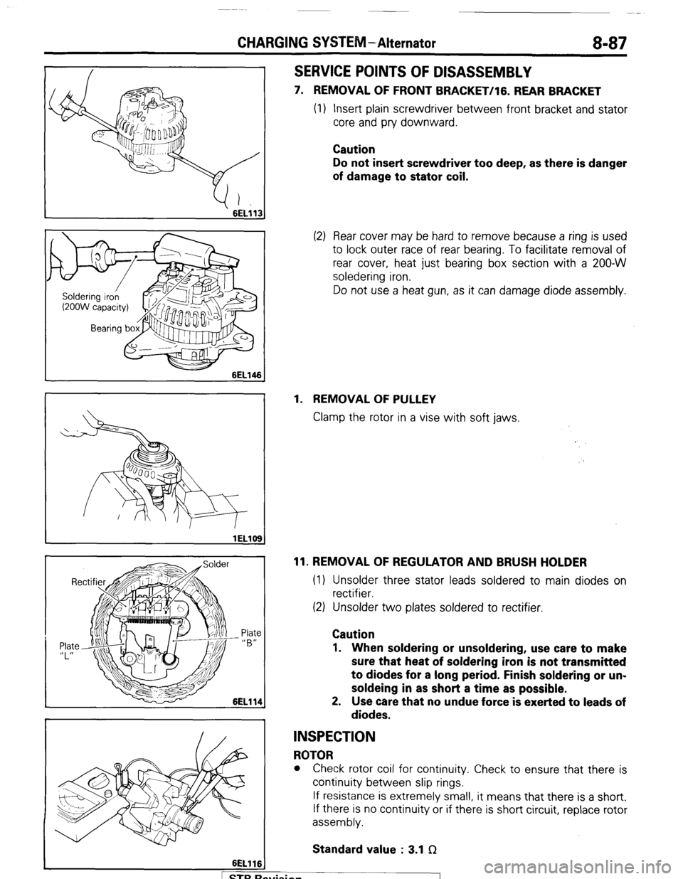
SERVICE POINTS OF DISASSEMBLY
7. REMOVAL OF FRONT BRACKET/lG. REAR BRACKET
(1) Insert plain screwdriver between front bracket and stator
core and pry downward.
Caution
Do not insert screwdriver too deep, as there is danger
of damage to stator coil.
(2) Rear cover may be hard to remove because a ring is used
to lock outer race of rear bearing. To facilitate removal of
rear cover, heat just bearing box section with a 200-W
soledering iron.
Do not use a heat gun, as it can damage diode assembly.
1. REMOVAL OF PULLEY
Clamp the rotor in a vise with soft jaws.
11. REMOVAL OF REGULATOR AND BRUSH HOLDER
(1) Unsolder three stator leads soldered to main diodes on
rectifier.
(2) Unsolder two plates soldered to rectifier.
Caution
1. When soldering or unsoldering, use care to make
sure that heat of soldering iron is not transmitted
to diodes for a long period. Finish soldering or un-
soldeing in as short a time as possible.
2. Use care that no undue force is exerted to leads of
diodes.
INSPECTION
ROTOR
l Check rotor coil for continuity. Check to ensure that there is
continuity between slip rings.
If resistance is extremely small, it means that there is a short.
If there is no continuity or if there is short circuit, replace rotor
assembly.
Standard value : 3.1 f2
. . .
I 1 STB hewsion
Page 108 of 284

8-88 CHARGING SYSTEM-Alternator
6EL115
3ELOlO
lELll0
lELll1
A
) STBRc
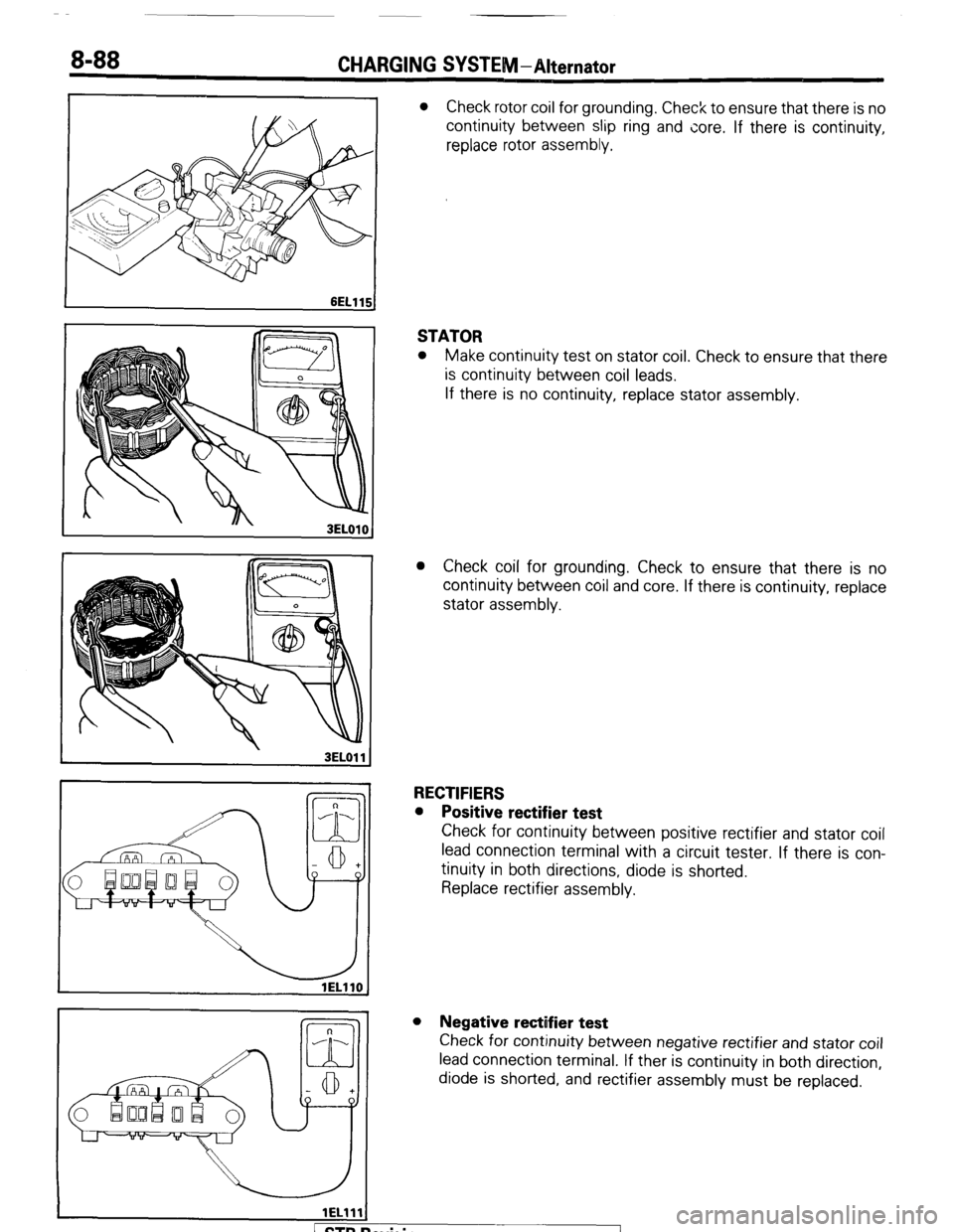
l Check rotor coil for grounding. Check to ensure that there is no
continuity between slip ring and core. If there is continuity,
replace rotor assembly.
STATOR
l Make continuity test on stator coil. Check to ensure that there
is continuity between coil leads.
If there is no continuity, replace stator assembly.
l Check coil for grounding. Check to ensure that there is no
continuity between coil and core. If there is continuity, replace
stator assembly.
RECTIFIERS
l Positive rectifier test
Check for continuity between positive rectifier and stator coil
lead connection terminal with a circuit tester. If there is con-
tinuity in both directions, diode is shorted.
Replace rectifier assembly.
l Negative rectifier test
Check for continuity between negative rectifier and stator coil
lead connection terminal. If ther is continuity in both direction,
diode is shorted, and rectifier assembly must be replaced.
evision
-7
Page 118 of 284

8-98 STARTING SYSTEM -Starter Motor
Pinion
6EL003
lEL113
/ Field coil wire
Field coil wire
4. Check pinion to stopper clearance (pinion gap) with a feeler
gauge.
Standard value : 0.5-2.0 mm (.020-.079 in.)
5. If pinion gap is out of specification, adjust by adding or remov-
ing gaskets between magnetic switch and front bracket.
PULL-IN TEST OF MAGNETIC SWITCH
1. Disconnect field coil wire from M-terminal of magnetic switch.
2. Connect a 12V battery between S-terminal and M-terminal.
Caution
This test must be performed quickly (in less than 10 sec-
onds) to prevent coil from burning.
3. If pinion moves out, then pull-in coil is good. If it doesn’t,
replace magnetic switch.
HOLD-IN TEST OF MAGNETIC SWITCH
1.
2. Disconnect field coil wire from M-terminal of in;ignetic switch.
Connect a 12V battery between S-terminal and body.
Caution
This test must be performed quickly (in less than 10 sec-
onds) to prevent coil from burning.
3. If pinion remains out, everything is in order. If pinion moves in,
hold-in circuit is open. Replace magnetic switch.
1 ST6 Revision