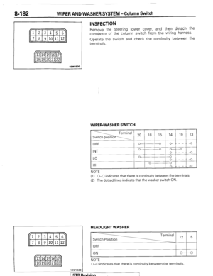
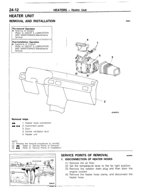
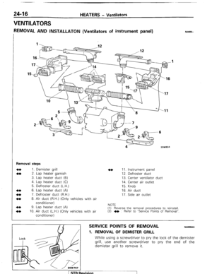
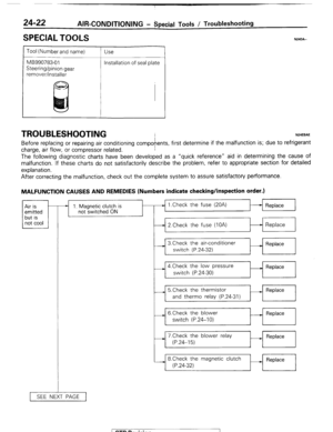
Page 1 of 284

Service Manual
MONTERO
1987 : Volume 2
FOREWORD
This Service Manual has been prepared with the
latest service information available at the time of
publication. It is subdivided into various group
categories and each section contains diagnosis,
disassembly, repair, and installation procedures
along with complete specifications and tightening
references. Use of this manual will aid in properly
performing any servicing necessary to maintain or
restore the high levels of performance and reliability
designed into these outstanding vehicles.
WE SUPPORT
VOLUNTARY TECHNICIAN
CERTIFICATION THROUGH
MITSUBISHI MOTOR SALES OF AMERICA. Inc.
Mitsubishi Motors corporation reserves the right to make changes in
design or to make additions to or improvements in its products without
imposing any obligations upon itself to install them on its products
previously manufactured.
I
GROUP/SECTION INDEX ‘kme-.
INTRODUCTION ..............................
Electrical ...........................................
Electrical System Parts
Location .........................................
Relays, Control Units, Sensors,
Fuses, Groundings
Inspection of Harness
Connector ......................................
Wiring Harness .............................
Charging System ..........................
Starting System ............................
Ignition System .............................
Meters and Gauges ......................
Lighting System .............................
Wiper and Washer System ..........
Horn ...............................................
Accessory ......................................
Audio System ................................
Back Door Window Defogger ......
Automatic Free-wheeling Hub
Indicator System ..........................
Heaters and Air-conditioning .........
Heaters ..........................................
Air-conditioning ............................
**, For Engine Chassis & Body refer to
0 1986 Mitsubishi Motors Corporation Printed in Japan
Page 2 of 284

2 INTRODUCTION - How To Use This Manual
HOW TO USE THIS MANUAL NOOBAAK
CONTENTS
The preceding page contains the GROUP INDEX
which lists the group title and group number.
PAGE NUMBERS
All page numbers consist of two sets of digits
separated by a dash. The digits preceding the dash
identify the number of the group. The digits follow-
ing the dash represent the consecutive page
number within the group. The page numbers can
be found on the top left or right of each page.
TEXT
Unless otherwise specified, each service procedure
covers all models. Procedures covering specific
models are identified by the model codes, or similar
designation (engine type, transmission type, etc.).
A description of these designations is covered in
this unit under “VEHICLE IDENTIFICATION”.
SERVICE PROCEDURES
The service steps are arranged in numerical order
and attentions to be paid in performing vehicle ser-
vice are described in detail in SERVICE POINTS.
DEFINITION OF TERMS
STANDARD VALUE
Indicates the value used as the standard for judging
the quality of a part or assembly on inspection or the
value to which the part or assembly is corrected and
adjusted. It is given by tolerance.
LIMIT
Shows the standard for judging the quality of a part
or assembly on inspection and means the maximum
or minimum value within which the part or assembly
must be kept functionally or in strength. It is a value
established outside the range of standard value. Installation steps
Indicates incidental operation
piiiKL=l-
Removal steps : The numbers before part names
correspond to numbers in the il-
lustration and indicate the order of
removal.
Disassembly steps : The numbers before part
names correspond to numbers
in the illustration, and indicate
the order of disassembly.
This is provided if installation
cannot be made in the reverse
order of “Removal steps”; omit-
ted if installation in the reverse
order of “Removal steps” is
possible.
.
Reassembly steps : I his IS provided It reassembly
cannot be made in the reverse
order of “Disassembly steps”;
omitted if reassembly in the
reverse order of “Disassembly
steps” is possible.
Classification of
SERVICE ROINTS
Oe : Removal
** : Installation
Oe : Disassembly
I)+ : Reassembly
Page 3 of 284

INTRODUCTION - H
ow To Use This Manual 3
-L
!
Page number
Group title
Section title
THERMOSTAT
REMOVAL AND INSTALLATION
I
I I
L
1 torque
Removal +
I s 0480031
Thermostat kit
Repair kit or set parts are
1. Connectw of water temperature switch
connector (Vehicles with an air condltlon-
eri
2 Connection of radiator upper hose
3 Water outlet fitting
4 Water outlet fitting gasket
B~C 5. Thermostat I
This number corresponds to
the number in “Removal
steps”, ” Disassembly
steps”, “Installation steps”
or “Reassembly steps”.
NOTE
(1)
(3)
q Nowreusable parts
-r Reverse the removal procedures to reinstall
12) l * : Refer to “Sewce Points of Installation”
SERVICE POINTS OF lNSTALLATlON--
45. INSTALLATION OF THERMOSTAT
Install the thermostat to the Intake manifold as illustrated.
Caution
The thermostat flange fits over the manifold seat;
ensure that the thermostat is not installed at an angle.
An explanation of procedures, notes, etc.
(and reassembly. ’ ’ -1 regarding removal installation disassembly
Page 4 of 284
INTRODUCTION - Vehicle Identification
VEHlCLE IDENTIFICATION
“&LE IDENTIFICATION NUMBER LOCATIOyo(lcAmm
The vehicle identification number (V.I.N.) is located on a plate
attached to the left top side of the instrument panel.
VEHICLE lDENTlFlCATlON CODE CHART PLATEo,,.,
All vehicle identification numbers contain 17 digits. The vehicle
number is a code which tells country, make, vehicle type, etc.
Country Make
!
J- A-
Japan Mitsu-
bishi Vehicle
type Line 4-
F- J-
Multi-
4001 Ibs. MON-
purpose or more TERO
vehicle
with
(MPW hydraulic
brakes
7-Truck
6th
digit
Price
class
2- Low
4- High 7th
8th 9th 10th
digit digit digit digit
Body Engine Check Model
digit year
3- E- 0 H-
3-door
2.6 liters 1 1987
metal- (155.9 2 year
top or C.I.D.) 3
van
9
X Plant
1 ZZ-Zer 1
NOTE
*“Check digit” means a single number or letter X used to verify the accuracy of transcription of vehicle indentification
number.
1 STB Revision
1 I : “’
Page 5 of 284

INTRODUCTION - Vehicle Identification
VEHICLE IDENTIFICATION NUMBER LIST
FEDERAL
VIN (except sequence number) Brand Engine displacement
JA4FJ43EoHJ
JA4FJ43EoHJ MITSUBISHI 2.555 liters
JA7FJ23EoHJ MONTERO (155.9 C.I.D.)
JA7FJ23EoHJ
5
NOOCC-
Model code
L042GVNJLF
L042GVRJLF
L042GTNSLF
L042GTRSLF
CALIFORNIA (Can also be sold in Federal states.)
VIN (except sequence number)
JA4FJ43EoHJ
JA4FJ43EoHJ
JA7FJ23EoHJ
JB7FJ23EoHJ Brand
MITSUBISHI
MONTERO Engine displacement
2.555 liters
(155.9 C.I.D.) Model code
L042GVNJLH
L042GVRJLH
L042GTNSLH
1 L042GTNSLH
OOK520
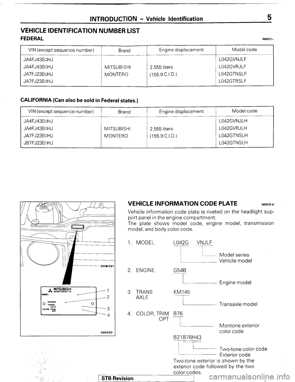
VEHICLE INFORMATION CODE PLATE NOOCO-A
Vehicle information code plate is riveted on the headlight sup-
port panel in the engine compartment.
The plate shows model code, engine model, transmission
model, and body color code.
1. MODEL L042G VNJLF
2. ENGINE G54B
I Engine model
3. TRANS
AXLE KM145
4. COLOR, TRIM
OPT 876
B2 1 B76H43
F
Two-tone exterior is shown by the Two-tone color code
Exterior code Transaxle model
Montone exterior
color code
exterior code followed by the two
color codes.
) STB Revision
._ :
Page 6 of 284
6 INTRODUCTION - Vehicle Identification
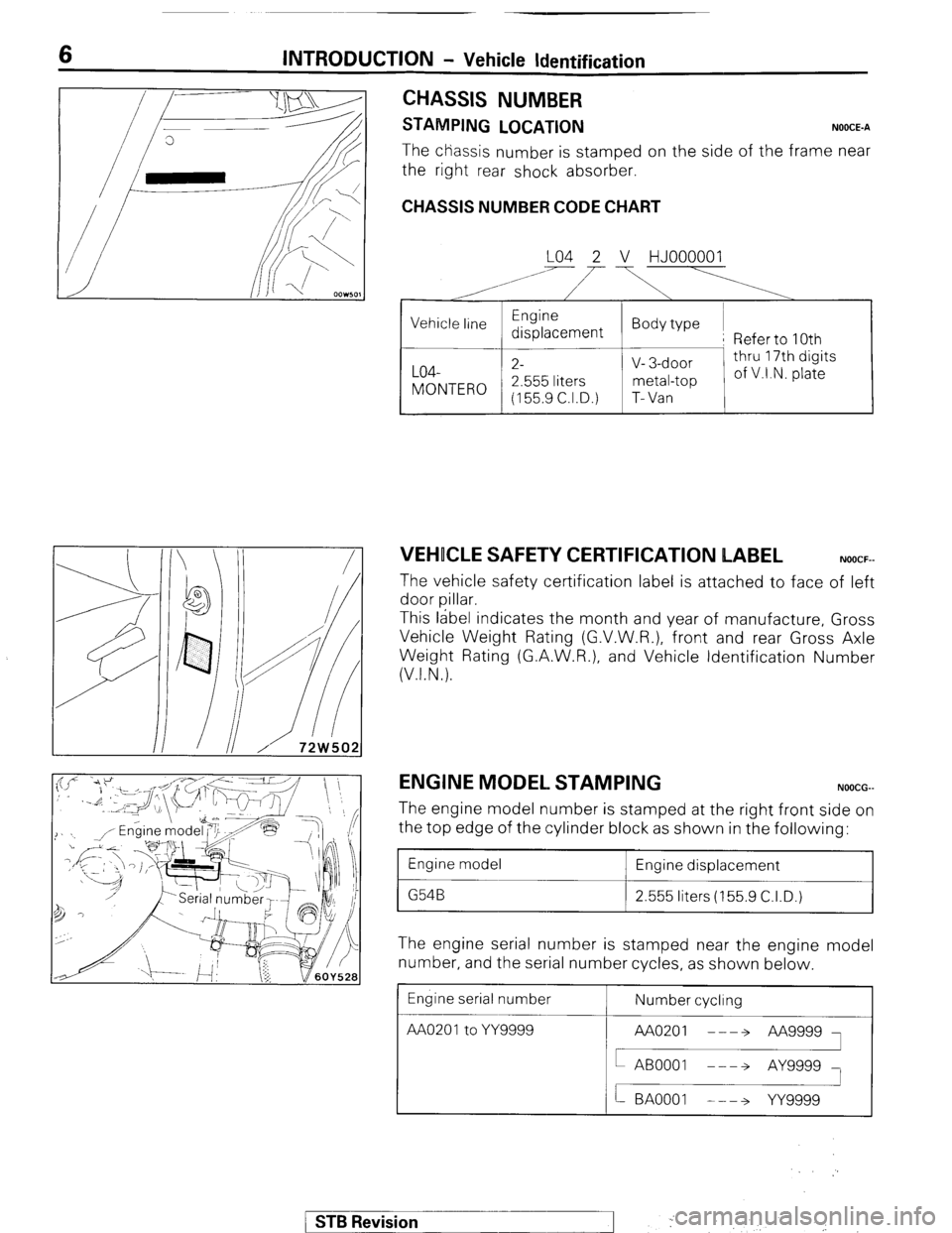
CHASSIS NUMBER
STAMPING LOCATION NOOCE-A
The chassis number is stamped on the side of the frame near
the right rear shock absorber.
CHASSIS NUMBER CODE CHART
LO4 2 V HJOOOOOl
A’ i’
,
VEHICLE SAFETY CERTIFICATION LABEL NOOCF-
The vehicle safety certification label is attached to face of left
door pillar.
This label indicates the month and year of manufacture, Gross
Vehicle Weight Rating (G.V.W.R.), front and rear Gross Axle
Weight Rating (G.A.W.R.), and Vehicle Identification Number
(V.I.N.).
ENGINE MODEL STAMPING NOOCG-
The engine model number is stamped at the right front side on
the top edge of the cylinder block as shown in the following:
1 Engine model
1 Engine displacement
1 2.555 liters (155.9 C.I.D.)
The engine serial number is stamped near the engine model
number, and the serial number cycles, as shown below
Engine serial number
AA020’toYY= Number cycling
/ STB Revision
--I f ,. ..-.
j ‘. .,
Page 7 of 284
INTRODUCTION - Vehicle Identification 7
BODY COLOR CODE
Exterior code
Monotone
B76
Cl9
H43
R52
s70
x15
Two-tone
B21 B76H43
C38C19X13
H15H43X13
R06R52X13
S69S7OX13
X45X1 5H43
NOOCH-
Body color
Dark blue (Metallic)
Brown (Metallic)
Silver (Metallic)
Red
Beige
Black
Silver (Metallic)/
Dark blue (Metallic)
Black/
Brown (Metallic)
Black/
Silver (Metallic)
Black/Red
Black/Beige
Black/
Silver (Metallic)
1 STB Revision
Page 8 of 284

8 INTRODUCTION - Precautions Before Service
r oorn,
FOOOl;
FOOOl8
PRECAUTIONS BEFORE SERVICE
PROTECTIN” THE VEHICLE NOODAAC
If theIre is a likelihood of damaging painted or interior parts
during service operations, protect them with suitable covers
(such as seat covers. fender covers, etc.).
REMOVAL AND DISASSEMBLY
When checking a malfunction, find the cause of the problem.
If it is determined that removal and/or disassembly is neces-
sary, perform the work by following the procedures contained
in this, Workshop Manual.
If punch marks or mating marks are made to avoid error in
assembly and facilitate the assembly work, be sure to make
them in locations which will have no detrimental effect on
performance and/or appearances.
If an area having many parts, similar parts, and/or parts which
are’ symmetrical right and left is disassembled, be sure to
arrange the parts so that they do not become mixed during the
assembly process.
1. Arrange the parts removed in the proper order.
2. Determine which parts are to be reused and which are to
be replaced.
3. If bolts, nuts, etc., are to be replaced, be sure to use only
the exact size specified.,
SPECIAL TOOLS
If other tools are substituted for the special tools to do service
or repair work, there is the danger that vehicle parts might be
damaged, or the mechanic might be injured; therefore, be
sure to use the special tool whenever doing any work for
which the use of one is specified.
PARTS TO IBE REPLACED
If any of the following parts are removed, they must be
replaced with new parts.
1. Oil seals
2. Gaskets (except rocker cover gasket)
3. Packings
4. O-rings
5. Lock washers
6. Cotter pins
7. Self-locking nuts
DO05111
STB Revision ,j .’