Page 257 of 284

AIR-CONDITIONING -Specifications
SPECIFICATIONS
GENERAL SPECIFICATIONS
24-2 1
N24CA-
Items Specifications
Compressor
Model
6P148lnclined-plate type
No. of cylinders and displacement
6 cylinders 6,148 (208,216)
cc. (U.S.fl. oz., Imp.fl.02.)
Refrigeration unit lubricant
cc. (U.S.fl. oz., Imp.fl.oz.) DENS0 oil 6 110 (3.7,3.9)
Protective equipment
OFF: 1 .O (22) ON:4.5 (39)
Cycling clutch switch
“C(“F)
OFF:210 (30) ON:230 (33)
Low pressure switch
kPa (psi)
OFF: 113 (235) ON:106(222)
Water temperature switch
“C (“F)
Air temperature thermostat
Freezor prevention
“C (“F) OFF:3 (37.4) ON:5 (41)
Burn out temperature 106 (222)
Fusible plug “C (“F)
R-l 2 600-900 (1.3-2.0)
Refrigerant and quantity
g (Ibs.1
SERVICE SPECIFICATIONS N24CE-
Items Specifications
Standard value
Drive belt deflection mm (in.) 17.20 (.7-.8)
Pressure plate to rotor clearance mm (in.)
0.4-0.7 (.02-.03)
TORQUE SPECIFICATIONS N24CG Items Nm ftlbs.
Suction hose to cooling unit 30-35 22-25
Liquid pipe to cooling unit 12-15 9-l 1
Liquid pipe to receiver drier 12-15 9-l 1
Suction hose to suction hose 30-35 22-25
Liquid pipe to liquid pipe 12-15 9-l 1
Liquid pipe to condenser 20-25 15-18
Suction hose to compressor 30-35 22-25
Discharge hose to compressor 20-25 15-18
Discharge hose to liquid pipe 20-25 15-18
Compressor shaft nut 15-17 11-13
Through bolt 25-26 18-20
/ STB Revision I
Page 258 of 284

24-22 AIR-CONDITIONING - Special TOOIS / Troubleshooting
SPECIAL TOOLS
Tool (Number and name)
MB990783-01
Steering/pinion gear
remover/installer Use
Installation of seal plate
TROUBLESHOOTING N24EBAE
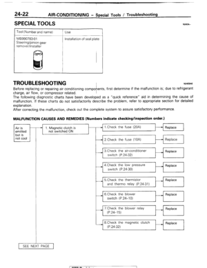
Before replacing or repairing air conditioning compofents, first determine if the malfunction is; due to refrigerant
charge, air flow, or compressor related.
The following diagnostic charts have been developed as a “quick reference” aid in determining the cause of
malfunction. If these charts do not satisfactorily describe the problem, refer to appropriate section for detailed
explanation.
N24DA.-
After correcting the malfunction, check out the complete system to assure satisfactory performance.
MALFUNCTION CAUSES AND REMEDIES (Numbers indicate checking/inspection order.)
1 not cool 1 Air is
emitted
but is * 1. Magnetic clutch is
not switched ON
SEE NEXT PAGE 1 Replace
1
I
I I
-4 2.Check the fuse (IOA)
t-l Replace
I
I I
I ,
I
3,Check the air-conditioner
__) Replace
switch (P.24-32)
I
4.Check the low pressure
switch (P.24-30) - Replace
---L 5.Check the thermistor
- Replace
and therm0 relay (P.24-31)
- 6.Check the blower
switch (P.24-10) - Replace
-i 7.Check the blower relay
M Replace
(P.24-15)
8.Check the magnetic clutch
(P.24-32) Replace
I
1 STB Revision
Page 259 of 284
AIR-CONDITIONING-Troubleshooting 24-23
1 CONTINUED FROM PREVIOUS PAGE] i
--) 2lnsufficient refrigerant
?
--) 3.Receiver drier clogged o Check the refrigerant amount _1 Supply
(P.24-29) refrigerant
. Check the receiver drier
.--+ Replace
(P.24-29)
--. 4.Abnormal rotation of Drive belt loose
compresspor
* (P.24-40) __) Adjust the
belt
1
- 5.Expansion valve clogged ) Check the expansion valve - Replace
(P.24-44) t
- 6.Poor compression of
compressor c Check the compressor
(P.24-32)) - Replace
1 STB Revision
Page 260 of 284

AIR-CONDITIONING-Service Adjustment Procedures
SERVICE ADJUSTMENT PROCQDURES 24-29 N24FDAD
MANIFOLD GAUGE SET INSTALLATUON Discharge
W gauge
Suction
gauge
Suction
gauge
valve Manifold Gauge Valves should be closed
when connecting the manifold gauge set to the service port of the
compressor and the discharge hose. The suction gauge valve at the left is opened to provide a passage between
the suction gauge and the center manifold outlet. The discharge gauge valve at the right is opened to provide a
passage between the discharge pressure gauge and the center manifold outlet.
Detailed instructions for proper use of the gauge set manifold are contained in the text covering each test and
service operation employing these gauges.
Suction Gauge; the left side of the manifold set is calibrated to register 0 to-100 kPa (0 to 30 in. of vacuum) and
0 to 1000 kPa (0 to 150 psi). This gauge is connected to the suction port of the compressor.
Discharge Gauge; the right of the manifold set is calibrated to register 0 to 2100 kPa (0 to 300 psi). For all
tests this gauge is connected to the discharge port of the system.
Center Manifold Outlet provides the necessary connection for a long service hose used when discharging the
system, using a vacuum pump to “pull a vacuum” before charging the system, and for connecting the supply of
refrigerant when charging the system
glass -
2OW724 N24FEAE The receiver drier assembly consists of; Drier reservoir, Refriger-
ant level sight glass and Fusible plug.
To Test the Receiver Drier (1) Operate the unit and check the piping temperature by
touching the receiver drier outlet and inlet.
(2) If there is a difference in the temperatures, the
received drier is restricted.
Replace the receiver drier.
SIGHT GLASS REFRlGERANT LEVEL TEST The sight glass is a refrigerant level indicator. To check the refrigerant level, clean the sight glass and start the
vehicle engine. Push the air conditioner button to operate the compressor, place the blower switch to high and
move the temperature lever to extreme left.
After operating for a few minutes in this manner, check the sight glass.
(1) If the sight glass is clear, the magnetic clutch is engaged, the compressor discharge line is warm and the
compressor inlet line is cool; the system has a full charge.
(2) If the sight glass is clear, the magnetic clutch is engaged and there is no significant temperature difference
between compressor inlet and discharge lines; the system has lost some refrigerant.
(3) If the sight glass is clear and the magnetic clutch is disengaged; the clutch is faulty or, the system is out of
refrigerant. Perform low pressure switch test to determine condition. Check low pressure switch and clutch coil
for electrical continuity.
1 STB Revision
Page 261 of 284
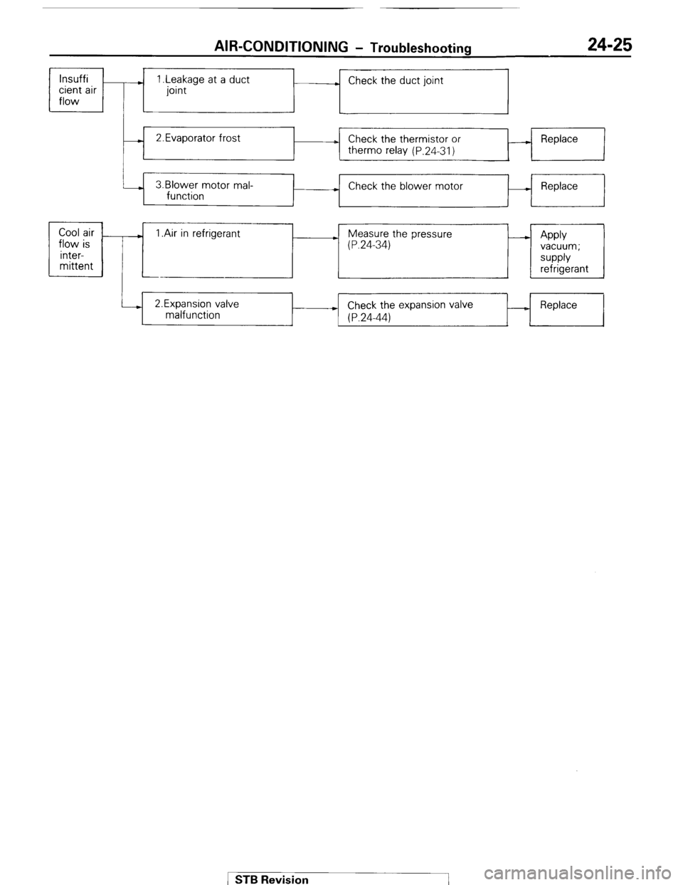
AIR-CONDITIONING - Troubleshooting 24-25
lnsuffi
cient air
flow ) 1 .Leakage at a duct
joint . Check the duct joint
- 2.Evaporator frost
D Check the thermistor or
therm0 relay (P.24-31) A Replace
3.Blower motor mal-
function + Check the blower motor - Replace
+
Cool air
.
flow is 1 .Air in refrigerant ) Measure the pressure
(P.24-34) - Apply
inter- vacuum;
mittent supply
refrigerant
i--) 2.Expansion valve
malfunction Check the expansion valve
* (P.24-44) _ Replace STB Revision
Page 262 of 284
24-26 AIR-CONDITIONING - Circuit Diagram
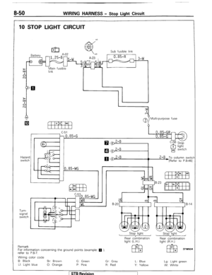
CIRCUIT DIAGRAM I N24ZB--
Ignition switch
Main
link Sub fusible link
(Fuse B)
I Battery
3
To turn signal flasher unit ~
0.85-RL [Refer to P.8-49.1
i
I 1 ,0.85-LW F
0.85-WB*
“yl lLG1 [Refer to P.8-62.1
C-C
Blower
motor
M
E!! Blower motor
T IA2
Ml
kFF -18
Heater relav N BI ower switch B L
EEJ LR LR resistor
LB LY
El3 LR LI
x’, $2
Wiring color code
B: Black Br: Brown G: Green
Gr: Gray L: Blue Lg: Light green
LI: Light blue 0: Orange P: Pink R: Red
Y: Yellow W: White
/ ST6 Revision
Page 263 of 284
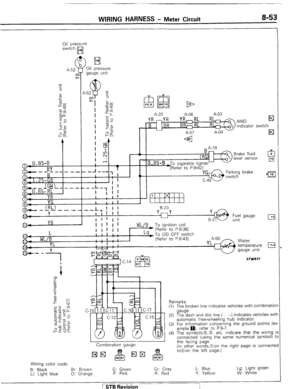
AIR-CONDITIONING - Circuit Diagram 24-27
Air conditioner relay
@,0.85-WB
El
Low pressure
switch
A-54 El
85-BW:0.85-BW ) To feed back carburetc
u control unit
A-25 [Refer to P.8-39.1
*20.85-BWr
*10.85-BWi& Vacuum solenoid
A-13 ++ valve
A-45
Condenser Condenser blower
blower motor motor relay
A
rl z-
BY
37W611 Magnetic
clutch
(compressor)
Remarks
(1) For information converning the ground points (exam-
ple.(l)m), refer to P.8-7.
(2) The symbols 0, 0, etc indicate that the wiring is
connected (using the same numerical symbol) to the
facing page (In other words, 0 on the right page is
connected to 0 on the left page.)
( STB Revision
Page 264 of 284

24-28 AIR-CONDITIONING-Safety Precautions
SAFETY PRECAUTIONS N24PAAB
SAFETY PRECAUTIONS
I
The refrigerant used in all air-conditioning installations is R-12. It is transparent and colorless in both the liquid and
vapor state. Since it has a boiling point of -29.8T (-21.7”F). at atmospheric pressure, it will be a vapor at all normal
temperatures and pressures. The vapor is heavier than air, non- flammable, and nonexplosive. It is nonpoisonous
except when it is in direct contact with open flame. It is noncorrosive except when combined with water. The
following precautions must be observed when handling R-12.
Caution
Wear
safety goggles when servicing the refrigeration system.
R-12 evaporates so rapidly at normal atmospheric pressures and temperatures that it tends to freeze anything it
contacts. For this reason, extreme care must be taken to prevent any liquid refrigerant from contacting the skin and
especially the eyes.
Always wear safety goggles when servicing the refrigeration part of the air- conditioning system. Keep a bottle of
sterile mineral oil handy when working on the refrigeration system. Should any liquid refrigerant get into the eyes,
use a few drops of mineral oil to wash them out. RI12 is rapidly absorbed by the oil. Next, splash the eyes with
plenty of cold water. Call your doctor immediately even though irritation has ceased after treatment.
Caution
Do not heat R-12 above 52°C (125°F).
In most instances, moderate heat is required to bring the pressure of the refrigerant in its container above the
pressure of the system when charging or adding refrigerant. A bucket or large pan of hot water not over 52°C
(125°F) is all the heat required for this purpose. Do not heat the refrigerant container with a blow torch or any other
means that would raise temperature and pressure above this temperature. Do not weld or steam clean on or near
the system components or refrigerant lines.
Caution
Keep R-12 containers upright when charging the system.
When metering R-12 into the refrigeration system, keep the supply tank or cans in an upright position. If the
refrigerant container is on its side or upside down, liquid refrigerant will enter the system and damage the
compressor.
Caution
Always work in a well-ventilated room.
Good ventilation is vital in the working area. Always discharge the refrigerant into the service bay exhaust system
or outside the building. Large quantities of refrigerant vapor in a small, poorly ventilated room can displace the air
and cause suffocation.
Although R-12 vapor is normally nonpoisonous, contact with an open flame can cause the vapor to become very
poisonous. Do not discharge large quantities of refrigerant in an area having an open flame. A poisonous gas is
producted when using the flame-type leak detector. Avoid inhaling the fumes from the leak detector.
Caution
Do not allow liquid refrigerant to touch bright metal.
Refrigerant will tarnish bright metal and chrome surfaces, and in combination with moisture’can severely corrode
all metal surfaces.
/ STB Revision
-I