INTRODUCTION - Geraeral Data and Specifications 17
GENERAL DATA AND SPECIFICATIONS
NOOHA-A
OOW556
Description L042G VNJ LFIH VRJLFIH
TNSLFIH TRSLF/H
Vehicle dimensions mm (in.)
Overall length
Without tire
spare 0 3,960 (155.9) 3,960 (155.9) 3,960 (155.9) 3,960 (155.9)
With tire spare 0 3,995 (157.3) 3,995 (157.3) 3,995 (157.3) 3,995 (157.3)
Overall width 0 1,680 (66.1) 1,680 (66.1) 1,680 (66.1) 1,680 (66.1)
Overall height 0 1,840 (72.4) 1,840 (72.4) 1,850 (72.8) 1,850 (72.8)
Wheelbase 0 2,350 (92.5) 2,350 (92.5) 2,350 (92.5) 2,350 (92.5)
Tread Front @ 1,400 (55.1) 1,400 (55.1) 1,400 (55.1) 1,400 (55.1)
Rear 0 1,375 (54.1) 1,375 (54.1) 1,375 (54.1) 1,375 (54.1)
Overhang Front @ 745 (29.3) 745 (29.3) 745 (29.3) 745 (29.3)
Rear @ 900 (35.4) 900 (35.4) 900 (35.4) 900 (35.4)
Height at curb weight
(wt.)
Front bumper to ground
@ 480 (18.9) 480 (18.9) 480(18.9) 480 (18.9)
Rear bumper to ground 440(17.3) 440(17.3) 440(17.3) 440(17.3)
Minimum running ground : 210 (8.3) 210 (8.3) 210 (8.3) 210 (8.3)
clearance
Angle of approach @ 38 38 38” 38
Angle of departure @ 28 28” 28 28
Ramp breakover angle
@ 21” 21” 21” 21”
Vehicle weights kg (Ibs.)
Curb weight 1,479 (3,260) 1,493 (3,290) 1,440 (3,175) 1,460 (3,219)
Gross vehicle weight rating 1,910 (4,210) I,91 0 (4,210) 1,910(4,210) I,91 0 (4.210)
Gross axle Front 1 ,I 00 (2,425) 1 ,I 00 (2,425) 1 ,I 00 (2,425) 1,100 (2,425)
weight ratin!g~:+y~ Rear 1,450 (3,197) 1,450 (3,197) 1,450 (3,197) 1,450 (3,197)
Seating,c&ac&~ 4 4 2 2
.’ .’ :I’ ;.,* ..,, VU.,
,: ‘,_. : ., ”
,_;. ,; ,: 3,‘. r STB Revision
18 INTRODUCTION - General Data and Specifications
Description L042G VNJLFIH VRJ L.F/H TNSLFIH TRSLFIH
1
Engine
Model No. G54B
G54B G54B G54B
Type i In-line OHC
In-line OHC In-line OHC In-line OHC
Number of cylinders ‘4 4
4 4
Bore 91 .I mm (3.59 in.) 91 .I mm (3.59 in.) 91 ,I mm (3.59 in.) 91 .I mm (3.59 in.)
Stroke 98.0 mm (3.86 in.) 98.0 mm (3.86 in.) 98.0 mm (3.86 in.) 98.0 mm (3.86 in.)
Piston displacement
2,555 cm” 2,555 cm” 2,555 cm3
2,555 cm3
(155.9 CID) (155.9 CID) (155.9 CID) (155.9 CID)
Compression ratio 8.7
8.7 8.7
8.7
Firing order
I-3-4-2 I-3-4-2 1-3-4-2
1-3-4-2
Basic ignitron trming
7” BTDC ? 2” 7” BTDC ? 2” 7” BTDC 2 2” ‘7” BTDC ? 2”
Transmission &transfer case
Model No.
KM145 KM148 KM145 KM148
Type 5-speed 4-speed 5-speed 4-speed
manual automatic manual automatic
Cear ratio
Transmjssion 1 st
3.967 2.826 3.967
2.826
2nd
2.136 1.493 2.136
1.493
3rd 1.360
1 .ooo 1.360
1.000
4th
1.000 0.688 1 .ooo
0.688
5th
0.856 - 0.856
-
Reverse 3.578
2.703 3.578
2.703
Transfer case High 1.000
1.000 1.000
1 ,040
Low 1.944
1.944 1.944
1.944
Final ring ratio
gear 4.625 4.625 4.625
4.625
Zlutch
Type Dry single
- Dry single
-
disc & disc &
diaphragm diaphragm
spring spring
Chassis
Tire size
Front suspension
P225/75R15
Type
Spring constant
(Wheel position)
Rear suspension
Type
Spring constant
At load of 1 ,OOO-2,500 N
(220-551 Ibs.)
At load of 4,670-8,870 N
(1,030-I ,955 tbs.) Wishbone compression type
22 N/mm (123 Ibs./in.)
Asymmetrical semi-elliptic leaf spring
22 N/mm (123 Ibs./in.)
50 N/mm (280 Ibs./in.)
1 STB Revision ..,j ; : * :
8-1
ELECTRICAL
CONTENTS
NOBAA-
ACCESSORY ......................................................
188
Cigarette Lighter ............................................
,190
Clock ...............................................................
,191
AUDIO SYSTEM ................................................
.192
AUTOMATIC FREE-WHEELING HUB
INDICATOR SYSTEM ........................................
208
Automatic Free-wheeling Hub
Indicator Control Unit
..................................... ,216
Pulse Generator ..............................................
215
BACK DOOR WINDOW DEFOGGER
................ .203
Defogger switch ............................................
,206
Printed Heater Lines
...................................... ,207
CHARGING SYSTEM .........................................
71
Alternator ........................................................
83
Service Adjustment Procedures
..................... 77
Battery Charging ........................................
82
Inspection of Battery ..................................
81
Output Current Test ...................................
78
Regulated Voltage Test ..............................
79
Voltage Drop Test of Alternator Output
Wire ............................................................
77
ELECTRICAL SYSTEM PARTS LOCATION
...... 2
Diode ...............................................................
5
Fusible Link and Fuse
..................................... 6
Grounding .......................................................
7
Relay and Control Unit ....................................
2
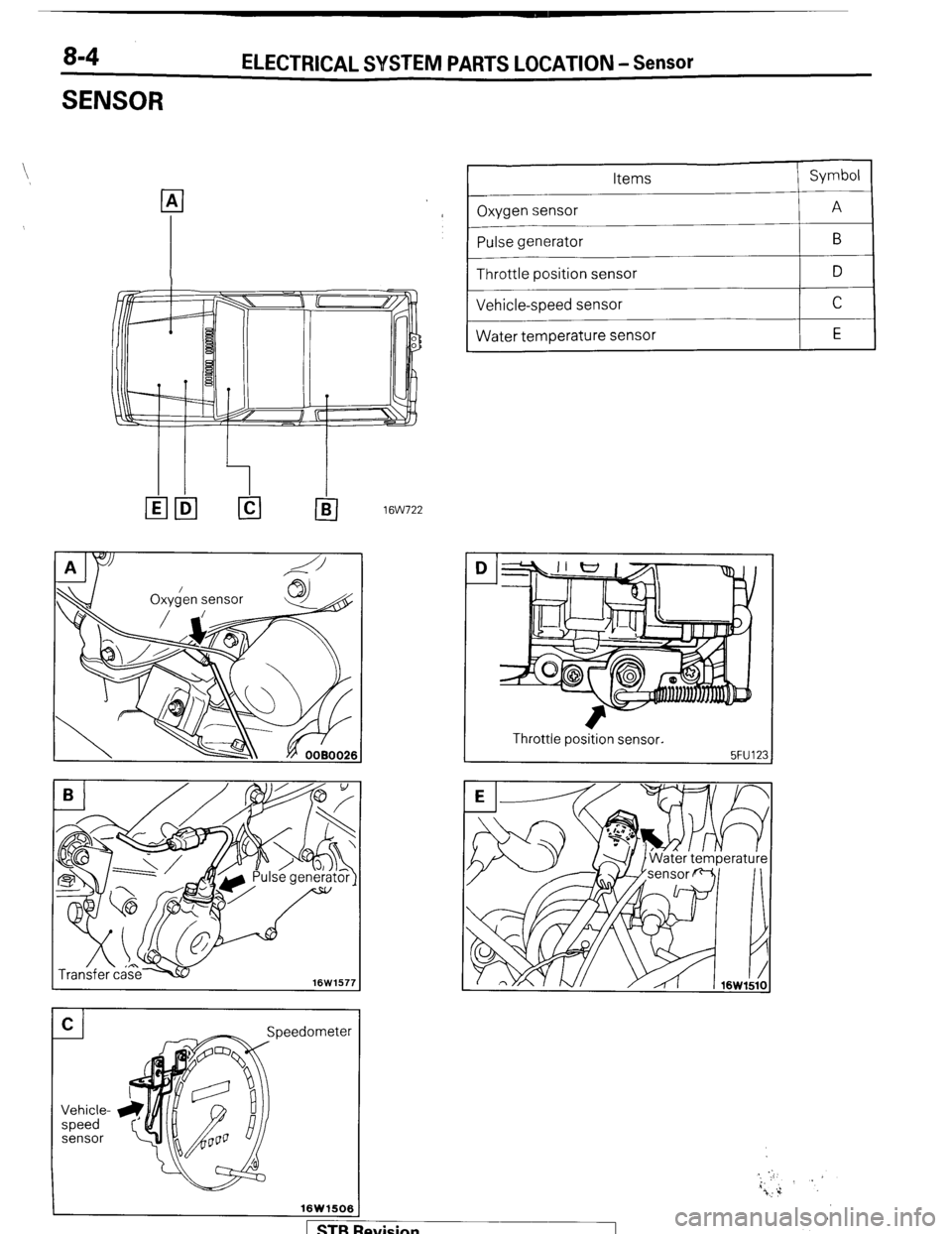
Sensor .............................................................
4
HORN ..................................................................
184
Horn Switch
.................................................... 187
IGNITION SYSTEM ............................................
105
Ignition Switch
................................................ 122
Ignition System ...............................................
1 14
Service Adjustment Procedures
.................... .l 1 1
Checking Ignition System
..........................
11 1
Checking Ignition Timing
...........................
11 1
Spark Plug Cable Test
................................
1 12
Spark Plug Test
.......................................... 1 12 INSPECTION OF HARNESS CONNECTOR ...... 9
Check for Improper Engagement of
Terminal .......................................................... 9
Continuity and Voltage Test for Connector .... 9
Engaging and Disengaging of Connector
Terminal ..........................................................
9
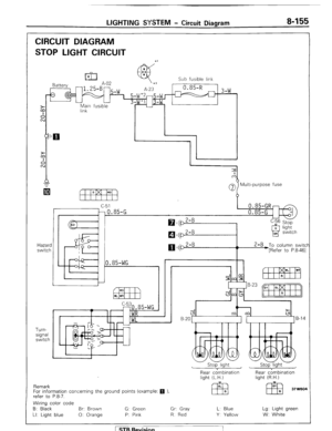
LIGHTING SYSTEM ........................................... 143
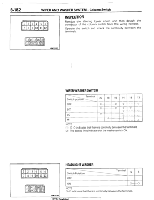
Column Switch
................................ .
.............. .I59
Dimmer Control Switch
................................. .I62
Hazard Warning Switch
................................. .I61
Headlight ........................................................ ,158
Service Adjustment Procedures
.................... .I57
Headlight Aiming .......................................
157
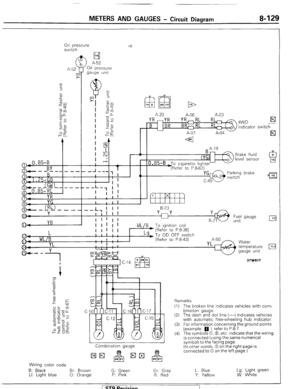
METERS AND GAUGES .................................... 123
Service Adjustment Procedures
.................... .I30
Fuel Gauge Simple Test ................................. .I31
Fuel Gauge Unit Inspection ........................... .I31
Oil Pressure Gauge Simple Test
.................... .I32
Oil Pressure Gauge Unit Simple Test
............ ,132
Speedometer Inspection
............................... .I30
Tachometer Inspection .................................. ,130
Voltage Meter Simple Test
............................ .I33
Water Temperature Gauge Simple Test
....... ..I3 1
Water Temperature Gauge Unit Inspection
. ..I3 2
STARTING SYSTEM .......................................... 91
Starter Motor ............ ....................................... 97
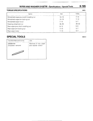
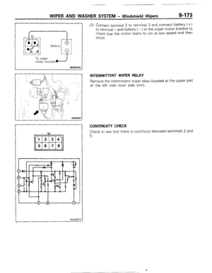
WIPER AND WASHER SYSTEM
....................... .163
WIRING HARNESS ............................................ 13
Centralized Junction ....................................... 69
Circuit Diagram ............................................... 34
Configuration Diagram .................................... 27
How to Read Wiring Diagrams ....................... 20
Troubleshooting .............................................. 13