Page 9 of 284

INTRODUCTION - Precautions Before Service 9
nm (in.)
so0059
PARTS
When replacing parts, use MITSUBISHI genuine parts.
VEHICLE WVASHING
If high-pressure car-washing equipment or steam car-washing
equipment is used to wash the vehicle, be sure to maintain the
spray nozzle at a distance of at least 300 mm (1 1.8 in.) from
any plastic parts and all opening parts (doors, luggage
compartment, etc.).
SERVICING THE ELECTRICAL SYSTEM
When servicing the electrical system, disconnect the negative
cable terminal from the battery.
Caution
Before connecting or disconnecting the negative cable, be
sure to turn off the ignition switch and the lighting switch.
(If this is not done, there is the possibility of semiconductor
parts being damaged.)
WIRING HARNESSES
1. Secure the wiring harnesses by using clamps so that there
is no slack. However, for any harness which passes to the
engine or other vibrating parts of the vehicle, allow some
slack within a range that does not allow the engine
vibrations to cause the harness to come into contact with
any of the surrounding parts. Then secure the harness by
using a clamp.
In addition, if a mounting indication mark (yellow tape) is
on a harness, secure the indication mark in the specified
location.
2. If any section of a wiring harness contacts the edge of a
part, or a corner, wrap the section of the harness with tape
or something similar in order to protect it from damage.
F161711
* :, :, 1 STB Revision
Page 10 of 284
INTRODUCTION - Precautions Before Service
16Rl263
16R1264 Y16347
3. When disconnecting a connector, be sure to pull only the
connector, not the harness.
4. Disconnect connectors which have catches by pressing in
the direction indicated by the arrows in the illustration.
5. Connect connectors which have catches by inserting the
connectors until they snap.
( STB Revision
‘.
Page 11 of 284

INTRODUCTION - Precautions Before Service 11
I
OOY63:
oOY58S IOA 15A
1 Permissible current 1
Nominal
size
0.3 mm2 AWG22 5A
05mm’ AWG 20
AWG18 ~ zi 13A
0.85 mm2 17A
1.25 mm2 AWG 16 12A 22A
2.0 mm2 AWG14 I 16A 30A
ELECTRICAL COMPONENTS
1. When installing any of the vehicle parts, be careful not to
pinch or damage any of the wiring harnesses.
2. Sensors, relays, etc., are sensitive to strong impacts.
Handle them with care so that they are not dropped or
mishandled.
3. The electronic parts used for relays, etc., are sensitive to
heat, If any service which causes a temperature of 80°C
(176°F) or more is performed, remove the part or parts in
question before carrying out the service.
FUSES AND FUSIBLE LINKS
1. If a blown-out fuse is to be replaced, be sure to use only a
fuse of the specified capacity. If a fuse of a capacity larger
than that specified is used, parts may be damaged and the
circuit may not be protected adequately.
Caution
If a fuse is blown-out, be sure to eliminate the cause of
the problem before installing a new fuse.
2 If additional optional equipment is to be installed in the
vehicle, follow the procedure listed in the appropriate
instruction manual; however, be sure to pay careful
attention to the following points:
(1) In order to avoid overloading the wiring, take the
electrical current load of the optional equipment into
consideration, and determine the appropriate wire size.
(2) Where possible, route the wiring through the existing
harnesses.
I Revision
Page 12 of 284

12 INTRODUCTION - Precautions Before Service
(3) If an ammeter or similar instrument is to be connected
to a live-wire circuit, use tape to protect the wire, use a
i clamp to secure the wire, and make sure that there is
, no contact with any other parts.
(4’) Be sure to provide a fuse for the load circuit of the
optional equipment.
FooO281
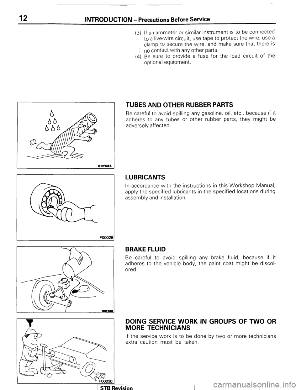
TUBES AND OTHER RUBBER PARTS
Be careful to avoid spilling any gasoline, oil, etc.. because if it
adheres to any tubes or other rubber parts, they might be
adversely affected.
LUBRICANTS
In accordance with the instructions in this Workshop Manual,
apply the specified lubricants in the specified locations during
assembly and installation.
BRAKE FLUID
Be careful to avoid spilling any brake fluid, because if it
adheres to the vehicle body, the paint coat might be discol-
ored.
DOING SERVICE WORK IN GROUPS OF TWO OR
MORE TECHNICIANS
If the service work is to be done by two or more technicians
extra caution must be taken.
-FOOO3OI
1 STB Revision ’
:
Page 13 of 284

INTRODUCTION - Precautions Before Service 13
IKITE ON INSTALLATION OF RADIO EQUIPMW&
The computers of the electronic control system has been
designed so that external radio waves will not interfere with
their operation.
However, if antenna or cable of amateur transceiver etc. is
routed near the computers, it may affect the operation of the
computers, even if the output of the transceiver is no more
than 25W.
To protect each of the computers from interference by
transmitter (hum, transceiver, etc.), the following should be
observed.
1. Install the antenna on the roof.
2. Because radio waves are emitted from the coaxial cable of
the antenna, keep it 200 mm (8 in.) away from the
computers and the wiring harness. If the cable must cross
the wiring harness, route it so that it runs at right angles to
the wiring harness.
3. The antenna and the cable should be well matched, and
the standing-wave ratio* should be kept low.
4. A transmitter having a large output should not be installed
in the vehicle.
5. After installation of transmitter, run the engine at idle, emit
radio waves from the transmitter and make sure that the
engine is not affected.
High-frequency power supply If an antenna and a cable having different impedances are
connected, the input impedance Zi will vary in accordance
with the length of the cable and the frequency of the
transmitter, and the voltage distribution will also vary in
accordance with the location.
The ratio between this maximum voltage and minimum
voltage is called the standing-wave ratio. It can also be
represented by the ratio between the impedances of the
antenna and the cable.
The amount of radio waves emitted from the cable increases
as the standing-wave ratio increases, and this increases the
possibility of the electronic components being adversely
affected.
_. r.
; ST6 Revision
Page 14 of 284

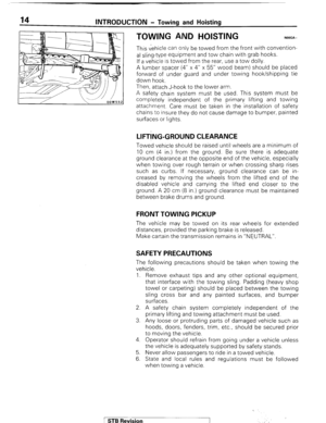
INTRODUCTION - Towing and Hoisting
TOWING AND HOISTING NOOGA-
This vehicle can only be towed from the front with convention-
al sling-type equipment and tow chain with grab hooks.
If a vehicle is towed from the rear, use a tow dolly.
A lumber spacer (4” x 4” x 55” wood beam) should be placed
forward of under guard and under towing hook/shipping tie
down hook.
Then, attach J-hook to the lower arm.
A safety chain system must be used. This system must be
completely independent of the primary lifting and towing
attachment. Care must be taken in the installation of safety
chains to insure they do not cause damage to bumper, painted
surfaces or lights.
LIFT!NG-GROUND CLEARANCE
Towed vehicle should be raised until wheels are a minimum of
10 cm (4 in.) from the ground. Be sure there is adequate
ground clearance at the opposite end of the vehicle, especially
when towing over rough terrain or when crossing sharp rises
such as curbs. If necessary, ground clearance can be in-
creased by removing the wheels from the lifted end of the
disabled vehicle and carrying the lifted end closer to the
ground. A 20 cm (8 in.) ground clearance must be maintained
between brake drums and ground.
FRONT TOWING PICKUP
The vehicle may be towed on its rear wheels for extended
distances, provided the parking brake is released.
Make cartain the transmission remains in “NEUTRAL”.
SAFETY PRECAUTIONS
The following precautions should be taken when towing the
vehicle.
1. Remove exhaust tips and any other optional equipment,
that interface with the towing sling. Padding (heavy shop
towel or carpeting) should be placed between the towing
sling cross bar and any painted surfaces, and bumper
surfaces.
2. A safety chain system completely independent of the
primary lifting and towing attachment must be used.
3. Any loose or protruding parts of damaged vehicle such as
hoods, doors, fenders, trim, etc., should be secured prior
to moving the vehicle.
4. Operator should refrain from going under a vehicle unless
the vehicle is adequately supported by safety stands.
5. Never allow passengers to ride in a towed vehicle.
6. State and local rules and regulations must be followed
when towing a vehicle.
1 STB Revision
‘
Page 15 of 284

INTRODUCTION - Towing and Hoisting
HOISTING
POST TYPE
15
Special care should be taken when raising the vehicle on a
frame contact type hoist. The hoist must be equipped with the
proper adapters in order to support the vehicle at the proper
locations. (See next page)
Conventional hydraulic hoists may be used after determining
that the adapter plates will make firm contact with the side
frame.
FLOOR JACK
A regular floor jack may be used under the front crossmember
or rear axle housing.
Caution
1. A floor jack must never be used on any part of the
underbody.
2. Do not attempt to raise one entire side of the vehicle by
placing a jack midway between front and rear wheels.
This practice may result in permanent damage to the
body.
EMERGENCY JACKING
Jack receptacles are located at the No. 2 crossmember and
rear axle housing to accept the jack supplied with the vehicle
for emergency road service. Always block the opposite wheels
and jack only on a level surface.
.::
. Y!’ ,,. I
.I
‘.
1 STB Revision
Page 16 of 284
16 INTRODUCTION - Towitng and Hoisting
FRAME CONTACT SUPPORT LOCATIONS
2,350 mm (92.5 in.) Section A-A
NOTE
The locations of the support point shown as Section A-A are
the same as those of the twin post hoist shown in the
illustration (OOW588) below.
oow553
LIFTING AND JACKING SUPPORT LOCATIONS
c Twin post hoist
m Floor lack
@B Emergency jacking (jack supplied with the vehicle)
OOW588