Page 209 of 284
ACCESSORY - Circuit Diagram 8-189
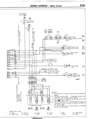
CIRCUIT DIAGRAM
LW
CIGARETTE LIGHTER / CLOCK CIRCUIT EB w
Sub fusible link
,-fs q M 15-W 5-W 25-W m ;I;
I I
-
Main fusible -
link Ignition switch
3e
I I
NN
,
Z-RW To
linht cnntrnl r&v I 4 0 n
I 1 - .J . __._ - -., [Refer to P.8-461
I 4 L-K A
To radio
GW [Refer to P.8-601 + 1 .25- GB
To hazard flasher unit4
[Refer to P.8-491
Multi-purpose fuse
illumination light
’ To heater control
illumination light
[Refer to P 8-511
r
i I
To combination meter BY
Wiring color code
B: Black LI: Light blue
Br: Brown 0: Orange
G: Green P: Pink
Gr: Gray R: Red
L: Blue Y: Yellow
Lg: Light green W: White
I
I - - m
I
N
Q
-
[Refer to P.8-521 -
To dimmer control switch BY
[Refer to P 8-511 .I
Remark 37W615
For information concerning the ground points (example: 0 ).
refer to P.8-7.
1 STB Revision
Page 210 of 284

8-190 ACCESSORY; - Cigarette Lighter
CIGARETTE LIGHTER
REMOVAL AND INSTALLATION NOEMJAE
Removal steps
1. Knob
2. Plug
3. Center panel
4. Plug
5. Nut
6. Socket
7. Outer case
8. Cigarette lighter bracket NOTE
Reverse the removal procedure to reinstall.
16W1555
INSPECTION
l Take out the plug, and check for a worn edge on the
element spot connection, and for shreds of tobacco or
other material on the element.
l Using an ohmmeter, check the continuity of the element.
l Confirm that there is no dirt on the surface of the socket.
CAUTIONS FOR USE OF THE CIGARETTE LIGHTER SOCKET
AS AUXILIARY POWER SOURCE
1. When using a “plug-in” type of accessory, do not use
anything with a load of more than 120W.
2. It is recommended that only the lighter be inserted in
the receptacle.
Use of “plug-in” type accessories may damage the
receptacle and result in poor retention of the lighter.
NOTE
The specified load should be strictly observed, because
overloaded cord burns the ignition switch and herness.
1 STB Revision
Page 211 of 284
ACCESSORY - Clock 8-191
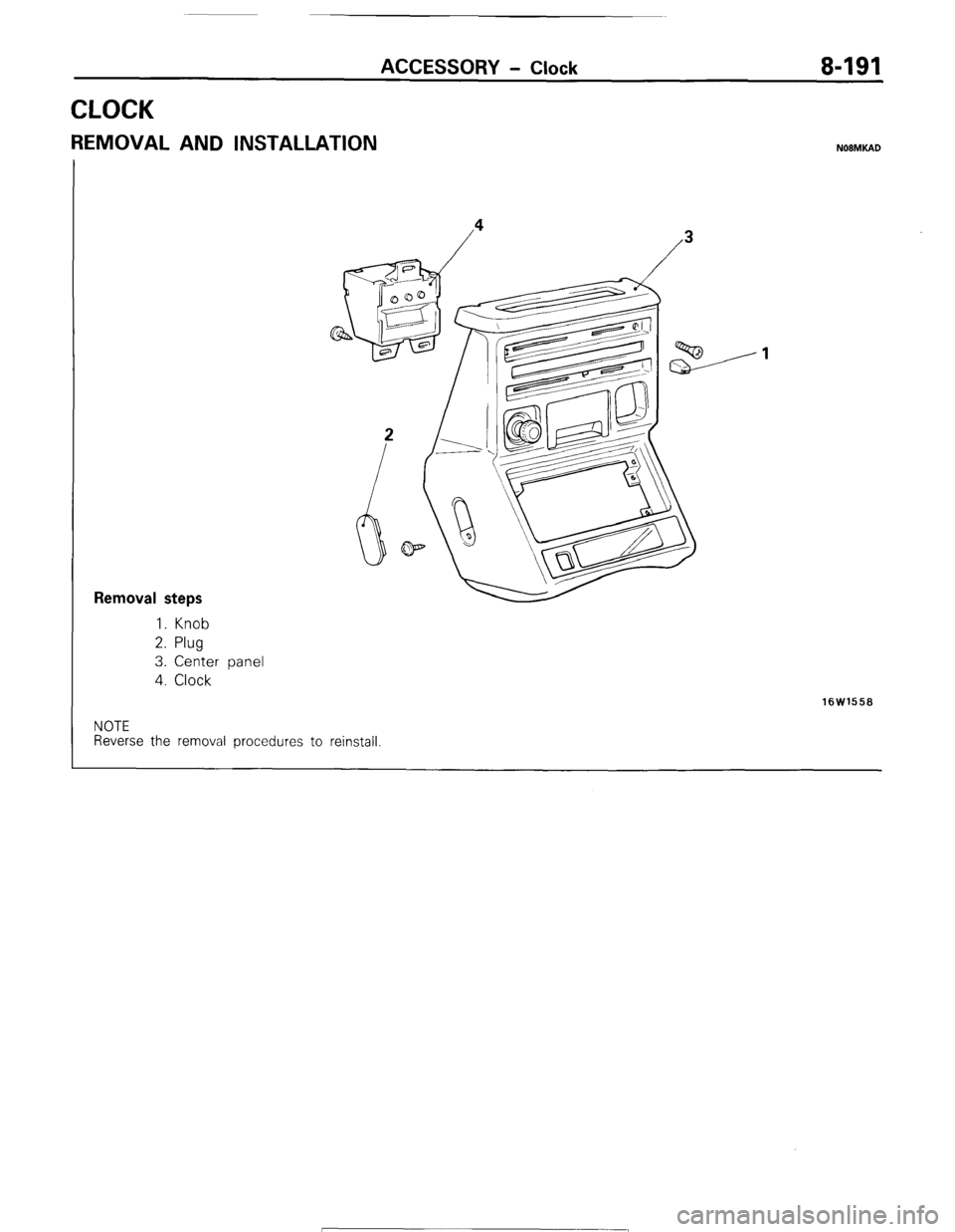
CLOCK
REMOVAL AND INSTALLATION NOBMKAD
Removal steps
1. Knob
2. Plug
3. Center panel
4. Clock
16W1558
NOTE
Reverse the removal procedures to reinstall 1 STB Revision
Page 212 of 284
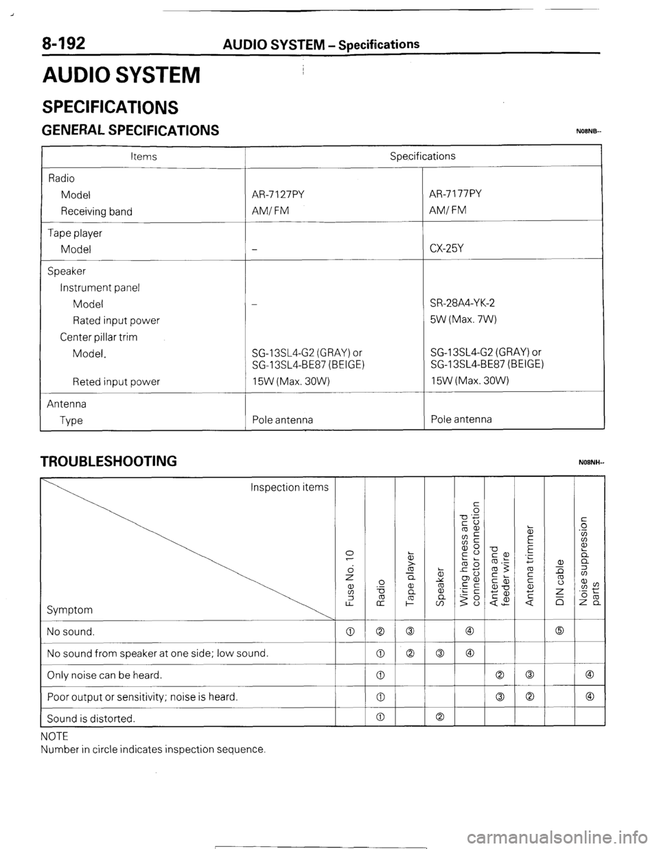
8-192 AUDIO SYSTEM - Specifications
AUDIO SYSTEM I
/
SPECIFICATIONS
GENERAL SPECIFICATIONS NOENB-
Items
Radio
Model
Receiving band
Tape player
Model
Speaker
Instrument panel
Model
Rated input power
Center pillar trim
Model.
Reted input power
Antenna
Type Spe,cifications
AR-7 127PY AR-7 177PY
AM/ FM AMI FM
-
CX-25Y
-_-
-
SR-28A4-Y K-2
5W (Max. 7W)
SG-13SL4-G2 (GRAY) or SG-13SL4-G2 (GRAY) or
SG-13SL4-BE87 (BEIGE) SG-13SL4-BE87 (BEIGE)
15W (Max. 30W) 15W (Max. 3OW)
Pole antenna Pole antenna
TROUBLESHOOTING
Symptom
NOTE
Number in circle indicates inspection sequence
( STB Revision
Page 213 of 284

AUDIO SYSTEM - Specifications 8-193
NOISE SOURCES
Source of Electrical System Noise
Ignition system
(1) Spark plug
(2) High tension cable
(3) Distributor Power generation system
(1) Ripple at contact between alternator
armature and carbon brush
(2) Spark from voltage regulator contact
!
Other electrical device
(1) Armature of wiper, blower and other
motors.
(2) Starter and switch when starting engine
(3) Spark from changeover switch
(4) Horn
(5) Contact of turn signal
(6) Loose contact of wiring harness
(7) Static electricity generated by tire or
generator drive-belt
(8) Voltage stability unit for instrument
Noise Sourse of Vehicle Equipment
Kind of noise
Whistling sound Equipment
Alternator Symptom of noise generation
Noise increases when accelerator pedal is
depressed and it subsides soon after engine
is stopped.
Scratching sound
Water temperature gauge unit Noise is produced while engine is running
and it persists for a while after engine
shutdown.
Fuel gauge unit Noise is produced at sudden acceleration,
driving on rough road or when ignition key is
placed to ON.
Jarring
Wish-wash,
wish-wash
Buzz, click Oil pressure switch
Flasher relay
Horn
Wiper motor
Washer motor Noise is produced with engine operation
and no noise is made when engine is idling.
Noise is produced with operation of turn
signal light
Noise is made when horn button is pressed
or released.
Whinning Noise is generated with the wiper speed.
Noise is made when washer is operated.
STB Revision
Page 214 of 284
8-194 AUDIO SYSTEM - Circuit Diagram
CIRCUIT DIAGRAM
I
RADIO/CASSETTE DECK CIRC,UIT
LW
033 w
Ignition switch
Battery A-02 IL-
Sub fusible link
0 1.25-B A-23 0.5-G 2 w
1 5-w 5-w ll5-w m -
u
Main fusible
link
N To light control
relav Z-RW 3 4
[Refer to P.8-461
Z-RW,,:
To air conditioner,LW
[Refer to P.8-561
To combination
By meter 4
[Refer to P.8-521
DIN Cable
I
/
J
I Y
=z
I
c- 45 -
It, /II
1 L
Radio Tape player
[ STB Revision
Page 215 of 284
AUDIO SYSTEM - Circuit Diagram 8-195
(L.H.)
C-65 Front speaker
YL B-03
Gr,=: (L.H.)
B-04
B-29
YR c
GrRC+
(R.H.)
B-2?’
Remarks
(1) For information concerning the ground points (exam-
ple: 0 ), refer to P.8-7.
(2) The symbols 0, 0, etc. indicate that the wiring is
connected (using the same numerical symbol) to the
facing page.
(in other words, 0 on the right page is connected to 0 on
the left page.)
Wiring color code
B: Black Br: Brown G: Green Gr: Gray L: Blue
LI: Light blue 0: Orange P: Pink R: Red Y: Yellow Rear speaker
Lg: Light green
W: White
/ STB Revision
Page 216 of 284

8-196 AUDIO SYSTEM - Service Adjustment Procedures
SERVICE ADJUSTMENT PROCEDURES
ANTkNNA TRUMMER NOBNIAA
70R0351
1.
2.
3.
1.
2.
3.
4.
5. The antenna trimmer is essential for matching the antenna
with the radio in order to obtain the maximum sensitivity of
the radio.
It must be adjusted with the antenna actually mounted on
the vehicle. If the trimmer is not adjusted properly, the
radio suffers from not only low sensitivity but also noises,
su’ch as external noise and noise from passing vehicles.
In the following cases, therefore, adjust it as described
below.
(1) When radio is installed.
(2) If antenna is replaced.
(3) If radio has low sensitivity.
(4) If radio is noisy.
AkTENNA TRIMMER ADJUSTMENT
Mgke the following preparations for adjustment:
(1)’ Turn the ignition key to the “ACC” position.
(2) Extend the antenna all the way.
(3) Tune accurately to a station near 1,400 kHz in order to
receive a broadcast in as weak an electric field as can
be barely received. If there is no station near 1,400 kHz,
tune to any high-frequency station (above 1,000 kHz)
available. If there are two or more stations near 1,400
kHz, choose the louder one.
(4) Set the volume control to the proper volume.
(5) Set the tone ccontrol to treble position.
Be sure that preparations 1 through 5 have been correctly
made.
Insert a screwdriver into the trimmer adjusting hole.
Tumrn the screwdriver clockwise or counterclockwise for
maximum sensitivity (maximum broadcast wave sound).
If the optimum sensitivity point cannot be found, check for
an antenna malfunction or a broken wire.
NOTE
The antenna trimmer of an electronic tuning radio does not
require adjustment.
/ STB Revision