Page 137 of 284

IGNITION SYSTEM-Ignition System 8417
Notch on
crankshaft
pulley
Stud 2
SERVICE POINTS OF INSTALLATION
9. INSTALLATION OF DISTRIBUTOR
(1) Align the notch on the crankshaft pulley with the timing
mark “T” on the timing indicator to set the engine so
that the No. 1 cylinder is at the compression top dead
center.
(2) Align mating mark on distributor housing with mating mark
on distributor driven gear.
(3) Install distributor to cylinder head while aligning mating
mark on distributor attaching flange with center of distrib-
utor installing stud and tighten nut.
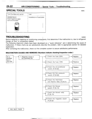
l-4. INSTALLATION OF SPARK PLUG CABLE
Improper arrangement of spark plug cables will induce voltage
between the cables, causing miss firing and developing a
surge at acceleration in high-speed operation. Therefore, be
careful to arrange the spark plug cables properly by the fol-
lowing procedure.
1. Install the spark plug cable clamps as shown in the illus-
tration.
2. The numerals on the support and clamp indicate the spark
plug cable No.
3. Pay attention to the following items when the spark plug
cables are installed.
(1) Install the cables securely to avoid possible contact
with metal parts.
(2) Install the cables neatly, ensuring they are not too
tight, loose, twisted or kinked.
( STB Revision
Page 138 of 284
8-118 IGNITION SYSTEM - Ignition System
SPARK PLUG CABLE INSTALLATION
I( 1
-4
-3
3
-1
-2
3
I 3
2 4
View P
/ STB Revision
5EL04
1
Page 139 of 284
IGNITION SYSTEM - Distributor
DISTRIBUTOR
DISASSEMBLY AND REASSEMBLY
8-119
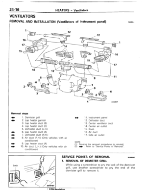
Disassembly steps
1. Breather
2. Distributor cap
3. Packing
4. Contact carbon
5. Rotor
6. Vacuum control
7. Ground wire
8. Lead wire
l + Adjustment of air gap
9. Igniter
4* 10. Rotor shaft
+*** 11. Signal rotor
l * 12. Breaker plate
4* 13. Spring retainer
4* 14. Governor spring
15. Governor weight
16. Lock pin
- Vehicles for
California
Vehicles except
for California
8
4**+ 17. Driven gear
18. Washer
19. “0” ring
20. Distributor shaft
21. Washer
22. Oil seal
23. Distributor housing
NOTE
(1) Reverse the disassembly procedures to reassemble.
(2) +e : Refer to “Service Points of Disassembly”.
(3) Hw: Refer to “Service Points of Reassembly”.
(4)
q : Non-reusable parts
lEL104 1 STB Revision
Page 140 of 284
8-120 IGNITION SYSTEM - Distributor
6ELO6i
ti Pin punch
II
1ELlOi
SERVICE POINTS OF DISASSEMBLY
10. DISASSEMBLY OF ROTOR SHAFT/l 1. SIGNAL ROTOR
Place igniter base on soft base (wooden block) and lightly tap
rotor shaft to remove it from signal rotor.
13. DISASSEMBLY OF SPRING RETAINERI14. GOVERNOR
SPRING
Remove two spring retainers with pliers and then remove two
governor springs.
17. DISASSEMBLY OF DRIVEN GEAR
(1) Mark location of driven gear on distributor shaft.
(2) Place driven gear on soft base (wood block) so that spring
pin can be removed.
(3) Using a pin punch, remove spring pin.
INSPECTION
Check according to the following provisions and repair or replace
anything faulty.
CAP ROTOR
(1) Ensure there are no cracks in the cap.
(2) Ensure that the electrodes of the cap and of the rotor are
undamaged.
(3) Wipe off any dirt from the cap or the rotor.
SERVICE POINTS OF REASSEMBLY
Before servicing be sure to clean and inspect all parts.
1 STB Revision
Page 141 of 284
IGNITION SYSTEM-Distributor 8-121
Distributor
w 6EL093
/” A
I -1-- Socket
17. REASSEMBLY OF DRIVEN GEAR Install
driven gear into distributor shaft at previously marked
location.
12. REASSEMBLY OF BREAKER PLATE Install igniter base to housing. Position the igniter base so that
the projection (A) fits into the groove (9).
11. REASSEMBLY OF SIGNAL ROTOR Install signal rotor to rotor shaft. Position the signal rotor so
that the dowel pin fits into the groove.
. ADJUSTMENT OF AIR GAP Adjust air gap between signal rotor and pick-up of igniter.
Standard value : 0.8 mm (.0315 in.)
1 STB Revision
Page 142 of 284
8-122 IGNITION SYSTEM - Ugnition Switch
IGNITION SWITCH
REMOVAL AND INSTALLATION
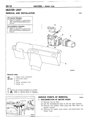
Removal steps
1. Lower column cover
2. Upper column cover
3. Cable band
4. Ignition switch
5. Key remaind switch NOTE Reverse the removal procedures to reinstall
NOEGLAE
16W1557
16UO36C
!I
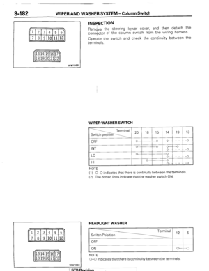
INSPECTION (1) Disconnect the wiring connector
from the ignition switch,
and connect an ohmmeter to the
switch side connector. (2) Operate the switch, and check the continuity between the
terminals.
START / Ignition switch
NOTE
O-C indicates that there is continuity between the terminals. 1 STB Revision -7
Page 143 of 284

METERS AND GAUGES-Specifications
METERS AND GAUGES
8-123
SPECIFICATIONS
GENERAL SPECIFICATIONS
METERS AND GAUGES NOEHB-
Items
Speedometer
Type
Tachometer
Type
Detection source
Fuel gauge
Type
Fuel gauge unit
Type
Water temperature gauge
Type
Water temperature gauge unit
Type
Oil pressure gauge
Type
Oil pressure gauge unit
Type
Inclinometer
Type
Damping system
Voltage meter
Type Specifications
Electromagnetic type
Pulse type
Ignition coil
Bimetal type (constant-voltage relay incorporated for 7V)
Variable resistance type
Bimetal type (7V operation)
Thermistor type
Bimetal type
Bimetal type
Gravity type
Oil-filled system
Bimetal type
INDICATOR AND WARNING LIGHTS
NOEHC-B
Items Specifications
Turn signal indicator lights
W 1.4 (74)
High beam indicator light W 1.4 (74)
Door-ajar warning light W 1.4 (74)
Fasten seat belt indicator light W 1.4 (74)
Brake warning light W 1.4 (74)
Charging warning light W 1.4 (74)
4WD indicator light W 1.4 (74)
EGR warning light W 1.4 (74)
Oil pressure warning light W 1.4 (74)
A/T oil temperature warning light
W 1.4 (74)
Overdrive indicator light
W 1.4 (74)
Free-wheeling hub indicator light W 1.4 (74)
NOTE
The values in parentheses denote SAE grade numbers.
1 STB Revision ”
Page 144 of 284

8-124
BUZZER METERS AND
GAUGES - Specifications
Items
Range of voltage used V
While buzzing (Terminal voltage at 13 V)
Sound pressure dB
Fundamental frequency Hz IO-16
53-7
goo* 150 Specifications
SERVICE SPECIFICATIONS
Items Specifications
Standard values
Speedometer indication error
Meter with “km/h” indication km/h
20 km/h f4
-1
40 km/h +4
0
80 km/h +5
0
120 km/h +5.5
+0.5
Meter with “mph” indication
mph
10 mph +- 1.5
25 mph + 1.5
50 mph +I.5
75 mph k 1.5
Tachometer indication error r/min
1,000 r/min *IO0
3,000 r/min +150
5,000 r/min f 250
Fuel gauge resistance value R
Between terminals 1 (power supply) and 2 (fuel gauge unit) 23-27
Between terminals 2 (fuel gauge unit) and 3 (ground) 122-l 48
Between terminals 1 (power supply) and 3 (ground) 100-l 20
Fule gauge unit resistance value R
Float point “F” 14.9-19.1
Float point “E” 113.5-l 26.5
Fuel gauge unit float position mm (in.)
Float point “F” 29.7-34.7 (1.169-l .366)
Float point “E” 183.8-185.8(7.236-7.315)
Water temperature gauge resistance value R
Between terminals 1 (power supply) and 2 (water 50-60
temperature gauge unit)
Water temperature gauge unit 90.5-I 17.5
resistance value R [at 70°C (158”F)l
Oil pressure gauge resistance value 1R 45-55
Voltage meter indication error V
IOV to.5
16V k 0.5
( ST6 Revision
-7