Page 238 of 284

24-2 HEATERS - General Information
GENERAL INFORMATION 24BAAD
The heater unit and the blower motor are the separate type.
For temperature control of the heater, the blend air system is used for excellent response and easy
temperature adjustment.
Because the damper in the blend air system controls the warm air, which passes through the heater core,
and fresh (cool) air, which does not pass througlh the core, minor adjustments of the temperature are
therefore possible, and the temperature’can be ,set to the optimum level.
The lap heater ducts (which provide warm air to th$ knee area for the front seats) and the-rear heater ducts
(which provide warm air to the foot area for the rebr seats) from the heater unit, plus the warm-water-type
rear heater, assure heating comfort throughout. :
Blower motor
/
2OW640
Rear heater duct ;;eselection
I Mode selection lever
I I
58W540 Temperature
Blower switch contra’ lever To defroster and
Blend air Air selection
demister damper damper
Fresh air
Mode selection
damper (VENT) To lap heater &@
duct To foot area
ro rear heater duct To rear heater duct 2OW706 Mode selection damper (FOOT/DEF)
1 ST6 Revision
Page 241 of 284

HEATERS - Service Adjustment Procedures 24-5
SERVICE DJUSTMENT PROCEDURES
TEMPERATURE CONTROL SYSTEM ADJUST-
ENT
N24FAAD
MODE SELECTION LEVER
1. Move the mode selection lever to each position and check
the air flow with the blower operating.
2. If the air flow is not correct for any position of the mode
selection lever, adjust the mode selection control wire. If
this adjustment does not help, adjust the damper.
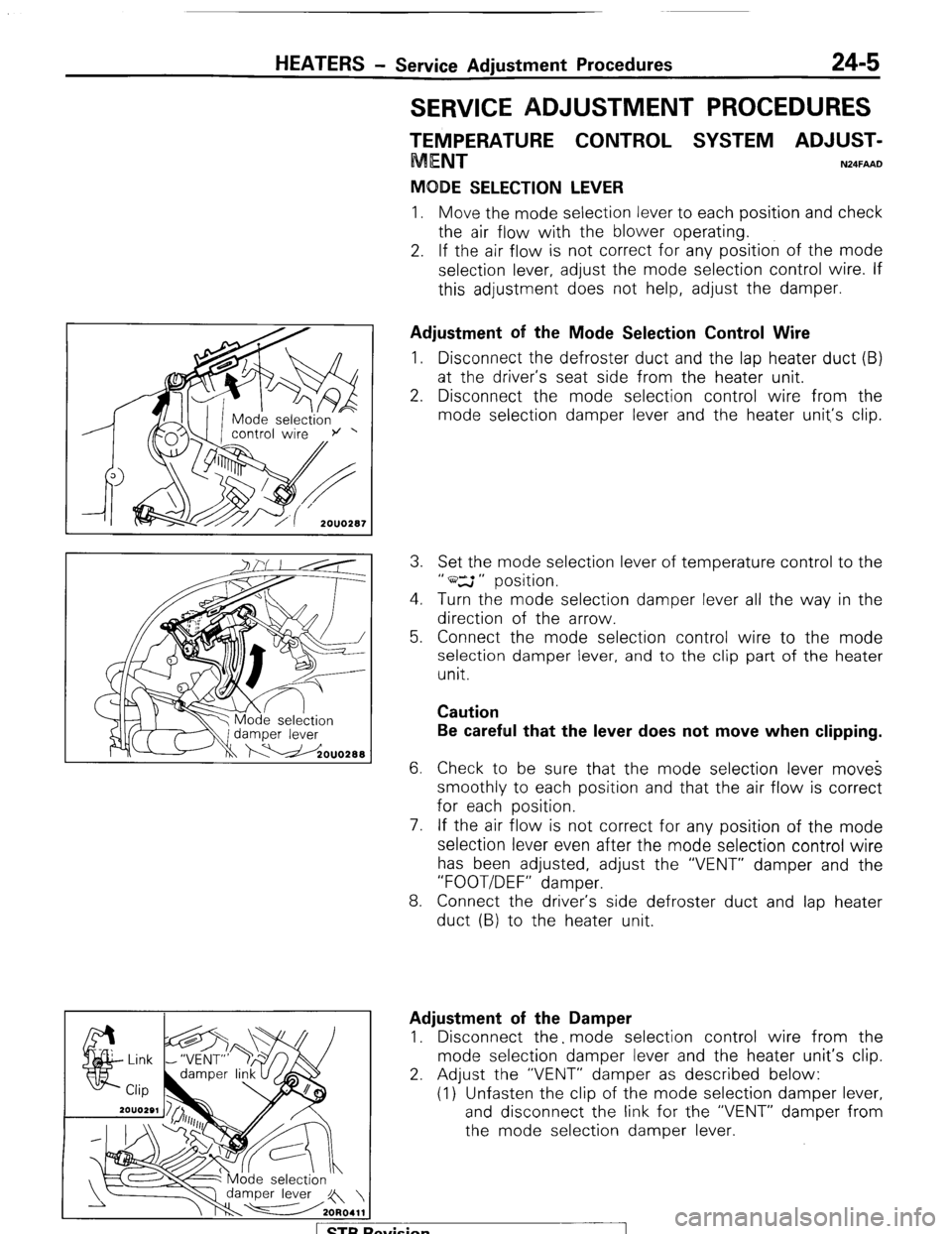
Adjustment of the Mode Selection Control Wire
1. Disconnect the defroster duct and the lap heater duct (B)
at the driver’s seat side from the heater unit.
2. Disconnect the mode selection control wire from the
mode selection damper lever and the heater unit,‘s clip.
3. Set the mode selection lever of temperature control to the
” ws ” position.
4. Turn the mode selection damper lever all the way in the
direction of the arrow.
5. Connect the mode selection control wire to the mode
selection damper lever, and to the clip part of the heater
unit.
Caution
Be careful that the lever does not move when clipping.
6. Check to be sure that the mode selection lever moves
smoothly to each position and that the air flow is correct
for each position.
7. If the air flow is not correct for any position of the mode
selection lever even after the mode selection control wire
has been adjusted, adjust the “VENT” damper and the
“FOOT/DEF” damper.
8. Connect the driver’s side defroster duct and lap heater
duct (B) to the heater unit.
Adjustment of the Damper
1. Disconnect the. mode selection control wire from the
mode selection damper lever and the heater unit’s clip.
2. Adjust the “VENT” damper as described below:
(1) Unfasten the clip of the mode selection damper lever,
and disconnect the link for the “VENT” damper from
the mode selection damper lever.
1 STB Revision
Page 269 of 284

AIR-CONDITIONING-Service Adjustment Procedures 24-33
2080113
6
Refrigerant
Compressor
Cl”“” tester T-7
Leak
, tester
pick up
tube
b/
2OUO316
TESTING SYSTEM FOR LEAKS N24FFA8
A leak is likely to occur where two components are connected
together. See illustration for possible locations.
The Leak Detector Torch is a butane gas-burning torch used to
locate a leak in any part of the refrigeration system. Refrigerant
gas drawn into the sampling or “sniffer” hose will cause the flame
to change color in proportion to the size of the leak. A very small
leak will produce a flame varying from yellowish-green to bright
green. A large leak will produce a brilliant blue flame.
Caution
Do not use the lighted detector in any place where explosive
gases, dust or vapors are present. Do not breathe the
fumes
that are produced by the burning of refrigerant gas. Large
concentrations of refrigerant in the presence of a live flame
become dangerously toxic.
If the flame remains bright yellow when the tester is removed
from a possible leak point, insufficient air is being drawn in through
the sampling tube, or the copper reaction wire is dirty.
(1) Assemble leak detector as shown be sure detector is seated
tightly over torch gasket.
(2) Holding torch upright screw-in butane charger (clockwise) until
punctured. (Do not use force).
(3) Screw-out butane charge (counterclockwise) about l/4 turn.
(4) Point torch away from body-then light escaping gas with
match. Always keep torch in upright position.
(5) Adjust flame by turning cartridge in or out as required.
(6) Allow 30 seconds to heat copper reaction wire.
Caution
Never remove butane charger while torch is lighted or in the
presence of any open flame.
(7) Examine all tube connectors and other possible lead points by
moving the end of the sampling hose from point to point.
Always keep torch in upright position. Since R-12 is heavier
than air, it is good practice to place the open end of sampling
hose directly below point being tested. Be careful not to pinch
sampling tube since this will shut off air supply to flame and
cause a color change.
(8) Watch for a change in the color of the flame. Small leaks will
produce a green color and large leaks a bright blue color. If
leaks are observed at tube fittings, tighten the connection,
using the proper flare wrenches, and retest.
1 STB Revision