Page 273 of 284

AIR-CONDITION1 G-Service Adjustment Procedures 24-37
water 2OUO326
(5) Start the vacuum pump and operate until the evaporator suc-
tion gauge registers at least-101 kPa (29.9 in.of vacuum).
If at least-101 kPa (29.9 in. of vacuum) cannot be obtained,
either the system has a leak or the vacuum pump is defective.
Check the vacuum pump. If the pump proves to be functioning
properly, the system has a leak. Charge the system with one
pound of refrigerant. Locate and repair all leaks. Discharge the
refrigerant and evacuate the system.
(6) Continue to operate the pump for at least five minutes.
(7) Close manifold valves. Turn off the vacuum pump and observe
evaporator suction gauge for two minutes. The vacuum level
should remain constant.
If the vacuum level falls off, the system has a leak. Charge the
system with one pound of refrigerant. Locate and repair all
leaks. Discharge the system and repeat evacuation procedure.
CHARGING THE SYSTEM
The refrigerant system must have been evacuated using the pre-
vious procedure before charging. Charge using only R-l 2 refriger-
ant R-l 2 is available in bulk tanks or small cans. Follow the safety
precautions for handling R-12 as listed in the beginning of this
group.
Charging with Small Cans
When using disposable cans of this type, follow carefully the can
manufactures instructions.
Caution
Never use these cans to charge into the high pressure side of
the system (compressor discharge port) or into a system that
is at high temperature, because the high system pressures
could be transferred into the charging can causing it to ex-
plode.
Keep the refrigerant manifold valves capped when not in use.
Keep a supply of extra refrigerant-can-to-refrigerant-manifold gas-
kets on hand so that gaskets can be replaced periodically. This will
insure a good seal without excessive tightening of the can or the
manifold nuts.
(1) Attach center hose from manifold gauge set to refrigerant
dispensing manifold. Turn refrigerant manifold valves com-
pletely counterclockwise so they are fully open. Remove pro-
tective caps from refrigerant manifold.
(2) Screw refrigerant cans into manifold. Be sure manifold-to-can
gasket is in place and in good condition. Tighten can and man-
ifold nuts to 8 to 11 Nm (6 to 8 ft.lbs.)
(3) Turn refrigerant manifold valves completely clockwise to
puncture the cans and close the manifold valves.
/ ST6 Revision
Page 274 of 284

24-38 AIR-CONDITIONING-Service Adjustment Procedures
(4) Purge the air from the charging line by loosening the charging
hose at the gauge set manifold and turning one of the refrig-
erant valves counterclockwise to release refrigerant. When
the refrigerant gas starts escaping from the loose connection,
re-tighten the hoses.
Caution
Never heat small refrigerant cans over 52°C (125°F) as they
mad explode.
(5) qully open all refrigerant manifold valves being used and place
the cans of refrigerant into a pan containing 52°C (125°F) water
will warm the charging can and aid in the transfer of the charge
into the system. Place the water pan and refrigerant cans on
a scale and note the weight.
(6) Jump the low pressure switch terminals located on the re-
ceiver drier so the clutch will remain engaged.
(7) Start the engine and move the controls to air conditioner
switch on and low blower position.
The low pressure switch will prevent the clutch from engaging
until refrigerant is added to the system. If the clutch does
engage, replace the switch before proceeding any further.
(8) Charge through the suction side of the system by slowly open-
ing the suction manifold valve. Adjust the valve as necessary
so charging pressure does not exceed 345 kPa (50 psi).
Maintain the temperature of the water in the pan by adding
warm water as necessary. Note the weight of water
added, to ensure accuracy when determining amount of
refrigerant added to system.
(9) Adjust the engine speed to a fast idle of approximately 1500
rpm.
(IO) When specified refried refrigerant charge 730 (1.6 Ibs.) has
entered the system, close the gauge set manifold valves,
refrigerant manifold valves, and reconnect wiring. Each
can contains 397 g (14 oz.) of R-12. Use 2 l/2 cans.
1 STB Revision
-1
Page 275 of 284

AIR-CONDITIONING-Service Adjustment Procedures 24-39
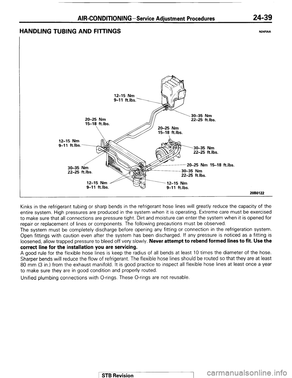
HANDLING TUBING AND FllTlNGS N24FlAA
12-15 Nm
9-l 1 ft.lbs.
20-25 Nm
15-18 ftlbs.
22-25 ftlbs.
15-18 ft.lbs.
20-25 Nm 15-18 ft
2080122 Kinks in the refrigerant tubing or sharp bends in the refrigerant hose lines will greatly reduce the capacity of the
entire system. High pressures are produced in the system when it is operating. Extreme care must be exercised
to make sure that all connections are pressure tight.‘Dirt and moisture can enter the system when it is opened for
repair or replacement of lines or components. The following precautions must be observed.
The system must be completely discharge before opening any fitting or connection in the refrigeration system.
Open fittings with caution even after the system has been discharged. If any pressure is noticed as a fitting is
loosened, allow trapped pressure to bleed off very slowly.
Never attempt to rebend formed lines to fit. Use the
correct line for the installation you are servicing. A good rule for the flexible hose lines is keep the radius of all bends at least 10 times the diameter of the hose.
Sharper bends will reduce the flow of refrigerant. The flexible hose lines should be routed so that they are at least
80 mm (3 in.) from the exhaust manifold. It is good practice to inspect all flexible hose lines at least once a year
to make sure they are in good condition and properly routed.
Unified plumbing connections with O-rings. These O-rings are not reusable.
1 STB Revision
Page 276 of 284

24-40 AIR-CONDITIONING-Service Adjustment Procedures
Nut
I Union
20110267
Tension pulley IOON (22 Ibs.1 Compressor
Crankshaft
pulley
I 2OY907 1 O-RING INSTALLATION
(1) Clean sealing surface.
(2) Make sure O-ring does not have any scratches.
(3) Connect fitting, install fastener, and torque to amount shown
in illustration.
The internal part of the refrigeration system will remain in a state
of chemical stability as long as pure-moisture-free R-l 2 and refrig-
erant oil is used. Abnormal amounts of dirt, moisture or air can
upset the chemical stability and cause operational troubles or even
serious damage if present in more than minute quantities.
When it is necessary to open the refrigeration system, have eve-
rything you will need to service the system ready so the system
will not be left open any longer than necessary. Cap or plug all
lines and fittings as soon as they are opened to prevent the en-
trance of dirt and moisture. All lines and components in parts stock
should be capped or sealed until they are ready to be used.
All tools, including the refrigerant dispensing manifold, the gauge
set manifold and test hoses should be kept clean and dry.
COMPRESSOR DRIVE BELT ADJUSTMENT N24FJAE
Satisfactory performance of the air-conditioning system is depen-
dent upon drive belt condition and tension. If the proper tensions
are not maintained, belt slippage will greatly reduce air- condition-
ing performance and drive belt life. To avoid such adverse effects,
the following service procedure should be followed:
(1) Any belt that has operated for a minimum of one half-hour is
considered to be a “used” belt. Adjust air- conditioning drive
belt at the time of new-car preparation.
(2) Check drive belt tension at regular service intervals and adjust
as needed.
Standard value :
17-20 mm (.67-.78 in.)
1 STB Revision
-7
Page 277 of 284

AIR-CONDITIONING -Service Adjustment Procedures 24-41
COMPRESSOR NOISE NWLM
When investigating an air conditioning related noise, you must first know the conditions when the noise occurs.
These conditions are: weather, vehicle speed, in gear or neutral, engine temperature or any other special
conditions.
Noises that develop during air- conditioning operation can often be misleading. For example: what sounds like a
failed front bearing or connecting rod, may be caused by loose bolts, nuts, mounting brackets, or a loose clutch
assembly. Verify accessory drive belt tension (power
steering, alternator or air pump). Improper accessory drive belt
tension can cause a misleading noise when the compressor is engaged and little or no noise when the compressor
is disengaged.
Drive belts are speed sensitive. That is, at different engine speeds, and depending upon belt tension, belts can
develop unusual noises that are often mistaken for mechanical problems within the compressor.
Adjustment Procedures
(1) Select a quiet area for testing. Duplicate conditions as much as possible. Switch compressor on and off several
times to clearly identify compressor noise.
To duplicate high ambient conditions (high head pressure), restrict air-flow through
condenser. Install
manifold gauge set to make sure discharge pressure does not exceed 2,070 kPa (300 psi).
(2) Tighten all compressor mounting bolts, clutch mounting bolt, and compressor drive belt. Check to assure clutch
coil is tight (no rotation or wobble).
(3) Check refrigerant hoses for rubbing or interference that can cause unusual noises.
(4) Check refrigerant charge (See “Charging the System”).
(5) Recheck compressor noise as in Step 1.
(6) If noise still exists, loosen compressor mounting bolts and retorque. Repeat Step 1.
(7) If noise continues, replace compressor and repeat Step 1.
1 STB Revision
Page 278 of 284
24-42 AIR-CONDITIONING - Air Conditioner Switch
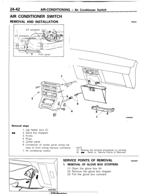
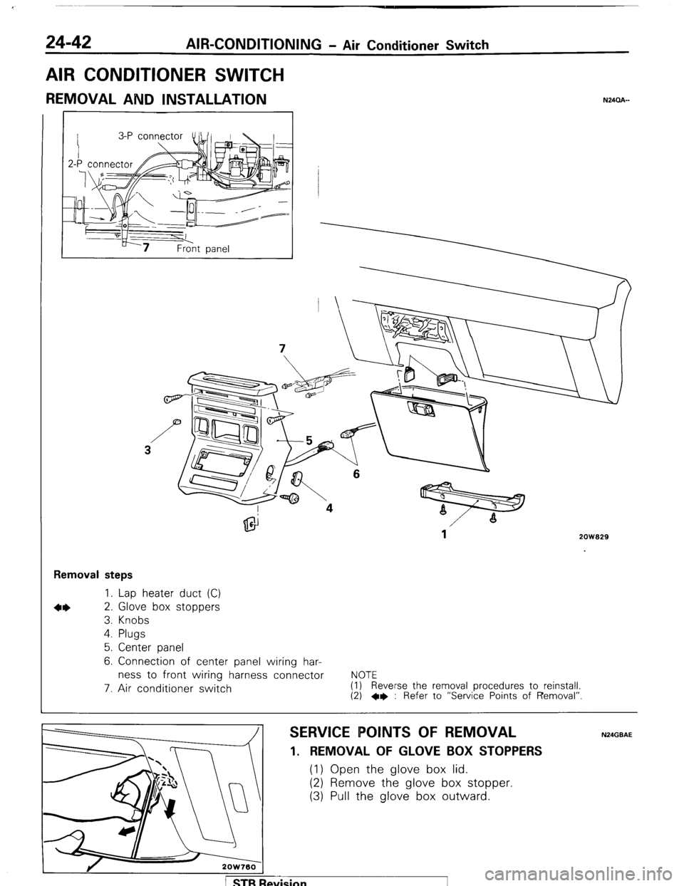
AIR CONDITIONER SWITCH
REMOVAL AND INSTALLATION N24CLA-
2ow929
Removal steps
1. Lap heater duct (C)
2. Glove box stoppers
3. Knobs
4. Plugs
5. Center panel
6. Connection of center panel wiring har-
ness to front wiring harness connector
7. Air conditioner switch
NOTE
(1) Reverse the removal procedures to reinstall. (2) +e : Refer to “Service Points of Removal”
SERVICE POINTS OF REMOVAL
1. REMOVAL OF GLOVE BOX STOPPERS
(1) Open the glove box lid.
(2) Remove the glove box stopper.
(3) Pull the glove box outward.
1 STB Revision
Page 279 of 284
AIR-CONDBTIONI G - Evaporator 24-43
EVAPORATOR
REMOVAL AND INSTALLATION
N24RA--
Pre-removal Operation
l
Discharge the refrigerant. (Refer to
P.24-36) Removal
steps ~~ 1. Liquid pipe connection
l + 2. Suction hose connection
3. Nut
4. Glove box
5. Main harness connector connection
6. Duct joint
7. Drain hose connection
8. Bolt
9. Evaporator
NOTE
(I) Reverse the removal procedures to reinstall.
(2) l
* : Refer to “Service Points of Installation”.
Nut
I Union
/
2OUO267
SERVICE POINTS OF REMOVAL Caution N24MAC If the hoses or pipes are disconnected, cap the hoses or pipes:
with a blank plug to prevent entry of dust, dirt, and water.
SERVICE POINTS OF INSTALLATION N24AOAE 2. APPLICATION OF COMPRESSOR OIL TO SUCTION
HOSE/l. LIQUID PIPE
Apply specified compressor oil to portions indicated
before installing the liquid pipe (C) and suction flexible
hose.
Specified oil : DENS0 oil 6
!vision
Page 280 of 284

24-44 AIR-CONDOTIONING-Evaporator
DISASSEMBLY AND REASSEMBLY
1
Disassembly steps
1. Air conditioner relay
2. Thermostat
3. Screw
4* 4. Clip
5. Evaporator case (upper)
6. Evaporator case (lower)
7. Evaporator assembly
+e l + 8. Expansion valve
NOTE
(1) Reverse the disassembly procedures to reassemble.
(2) +e : Refer to “Service Points of Disassembly”.
(3) l + : Refer to “Service Points of Reassembly”.
N24RE-- -6
2OW828
2OW718
2ow722
a 0-rina
Expansion
valve
O-rim
SERVICE POINTS OF DISASSEMBLY
4. REMOVAL OF CLIP
N24RFAB Remove the clips with a flat-blade screwdriver covered with a
shop towel to prevent damage to case surfaces.
8. REMOVAL OF EXPANSION VALVE Use two wrenches to loosen the flare nut on the pipe con-
nection (for both the inlet and outlet).
SERVICE POINTS OF REASSEMBLY N24RHAE
8. APPLICATION OF COMPRESSOR OIL TO EXPANSION
VALVE Apply specified compressor oil to the O-rings and install
the expansion valve to the evaporator assembly.
Specified oil : DENS0 oil 6
1 STB Revision