1987 MITSUBISHI MONTERO roof
[x] Cancel search: roofPage 13 of 284

INTRODUCTION - Precautions Before Service 13
IKITE ON INSTALLATION OF RADIO EQUIPMW&
The computers of the electronic control system has been
designed so that external radio waves will not interfere with
their operation.
However, if antenna or cable of amateur transceiver etc. is
routed near the computers, it may affect the operation of the
computers, even if the output of the transceiver is no more
than 25W.
To protect each of the computers from interference by
transmitter (hum, transceiver, etc.), the following should be
observed.
1. Install the antenna on the roof.
2. Because radio waves are emitted from the coaxial cable of
the antenna, keep it 200 mm (8 in.) away from the
computers and the wiring harness. If the cable must cross
the wiring harness, route it so that it runs at right angles to
the wiring harness.
3. The antenna and the cable should be well matched, and
the standing-wave ratio* should be kept low.
4. A transmitter having a large output should not be installed
in the vehicle.
5. After installation of transmitter, run the engine at idle, emit
radio waves from the transmitter and make sure that the
engine is not affected.
High-frequency power supply If an antenna and a cable having different impedances are
connected, the input impedance Zi will vary in accordance
with the length of the cable and the frequency of the
transmitter, and the voltage distribution will also vary in
accordance with the location.
The ratio between this maximum voltage and minimum
voltage is called the standing-wave ratio. It can also be
represented by the ratio between the impedances of the
antenna and the cable.
The amount of radio waves emitted from the cable increases
as the standing-wave ratio increases, and this increases the
possibility of the electronic components being adversely
affected.
_. r.
; ST6 Revision
Page 29 of 284

INSPECTION OF HARNESS CONNECTOR - Inspection of Harness Connector 8-9
Connect to
harness
16UO500
16R1317
8; 4 16R1319
INSPECTION OF HARNESS
CONNECTOR
NOECAM
CONTINUITY AND VOLTAGE TEST FOR CONNEC-
TOR
Following procedures shall be followed for testing continuity and
voltage at connector in order to prevent improper contact and
deterioration of waterproof in connector.
CONVENTIONAL (NON-WATERPROOF) CONNECTOR
Check shall be done by inserting a probing needle from harness
side.
WATER PROOF CONNECTOR
Caution.
Do not insert probing needle from harness side as it will de-
teriorates waterproof and cause for rusting. To inspect the
energized circuit, use the ECI checker.
CHECK FOR IMPROPER ENGAGEMENT OF TERMI-
NAL
When terminal stopper of connector is out of order, engagement
of male and female terminals becomes improper even when con-
nector itself is engaged perfectly and terminal sometimes slips out
to rear side of connector. Ascertain, therefore, that each terminal
does not come off connector by pulling each harness wire.
ENGAGING AND DISENGAGING OF CONNECTOR
TERMINAL
Connector which gives loose engagement shall be rectified by
removing female terminal from connector housing and raise its
lance to establish securer engagement. Removal of connector
housing and raise its lance to establish securer engagement. Re-
moval of connector terminal used for ECI and ELC 4 ,4/l control
circuit shall be done in the following manner.
COMPUTER CONNECTOR
(1) Insert screwdriver [1.4 mm (06 in.) width] as shown in the
figure, disengage front holder and remove it.
:
j ’ . _. 1 STB Revision
Page 30 of 284

8-10 INSPECTION OF HARNESS CONNECTOR - Inspection of Harness Connector
Housing lance
-5
1 16R1321
’ Needle
16Ffi322
Housing lance
16R1323 (2) Insert harness of terminal to be rectified deep into connector
from harness side and hold it there.
(3) Insert tip of screwdriver [1.4 mm (.06 in.) width] into connector
in a manner as shown in the figure, raise housing lance slightly
with it and pull out harness.
NOTE
Tool No. 753787-l supplied by AMP can be used instead
of screwdriver.
(4) Insert needle through a hole provided on terminal and raise
contact point of male terminal.
ROUND WATERPROOF CONNECTOR (1) Remove waterproof cap by using a screwdriver.
(2) Insert tip of screwdriver [1.4 mm (.06 in.) or 2.0 mm (.08 in.)
width] into connector in a manner as shown in the figure, raise
housing lance slightly with it and pull out harness.
(3) Insert screwdriver through a hole provided on terminal and
raise contact point of male terminal.
Page 31 of 284

INSPECTION OF HARNESS CONNECTOR - Inspection of Harness Connector 8-71
RECTANGULAR WATERPROOF CONNECTOR
(1) Disengage front holder by using a screwdriver and remove it.
(2) Insert tip of screwdriver [*0.8 mm (03 in.) width] into connec-
tor in a manner as shown in the figure, push it lightly to raise
housing lancer and pull out harness.
*If right size screwdriver is not available, convert a conven-
tional driver to suit the size.
Housing lance
16R13 26
16R1329
L 16R1326)
(2)
Terminal lance
16Rl330
1 STB Revision (3) Press contact point of male terminal down by holding a screw-
driver [1.4 mm (.06 in.) width] in a manner as shown in the
figure.
INJECTOR CONNECTOR
(1) Remove waterproof cap.
Insert tip of screwdriver [1.4
in a manner as shown in the
pull out harness. mm (06 in.) width] into connector
figure, press in terminal lance and
Page 45 of 284

Position of guide to prevent
improper connection
fl!liB
9-wire connector
WIRING HARNESS - How to Read Wiring Diagrams 8-25
IDENTIFYING CONNECTORS
In circuit diagrams, the connectors are indicated by symbolic
marks which show the number of their wires and whether they
are male,or female connectors.
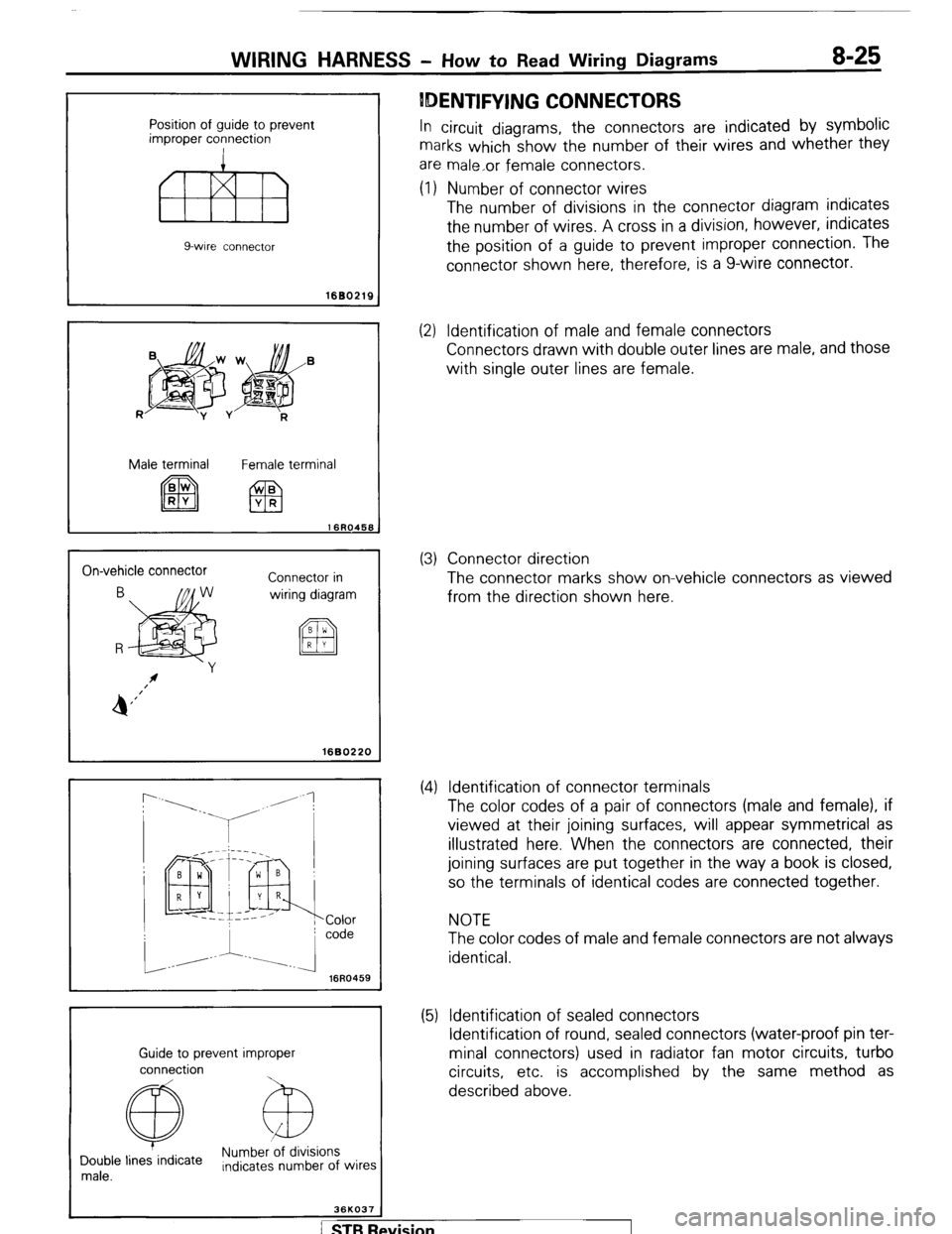
(1) Number of connector wires
The number of divisions in the connector diagram indicates
the number of wires. A cross in a division, however, indicates
the position of a guide to prevent improper connection. The
connector shown here, therefore, is a g-wire connector.
1680219
R
jpg$&’
-y v
R
Male terminal
Female terminal
On-vehicle connector
Connector in
wiring diagram
I 1680220
r
16R0459
Guide to prevent improper
connection
@ Numb&ions
Double lines indicate
male. Indicates number of wires
36KO37
(2) Identification of male and female connectors
Connectors drawn with double outer lines are male, and those
with single outer lines are female.
(3) Connector direction
The connector marks show on-vehicle connectors as viewed
from the direction shown here.
(4) Identification of connector terminals
The color codes of a pair of connectors (male and female), if
viewed at their joining surfaces, will appear symmetrical as
illustrated here. When the connectors are connected, their
joining surfaces are put together in the way a book is closed,
so the terminals of identical codes are connected together.
NOTE
The color codes of male and female connectors are not always
identical.
(5) Identification of sealed connectors
Identification of round, sealed connectors (water-proof pin ter-
minal connectors) used in radiator fan motor circuits, turbo
circuits, etc. is accomplished by the same method as
described above.
/ STB Revision
Page 52 of 284

8-32 WIRING HARNESS - Instrument Panel
3 INSTRUMENT PANEL
Connector symbol
C
C-65 c-04
C-06
C-64
C-63
C-61
CL57 C-b6 C!55 d54 c!5
Remarks
For information concerning the ground points (example:
q ),
refer to P.8-7.
C-01 Back door lock switch
C-02 Defogger switch
C-03 Kev reminder and seat belt
warning buzzer
c-04
pi;’ Combination meter
C-08 Diode
C-09 Rear wiper and washer switch
r&~}Oil pressure gauge
C-12 f;hybination gauge illumination
C-l 3 Blower switch
C-14 Combination gauge wiring
harness and front wiring harness
combination
C-15 F;hybination gauge illumination
C,::F}Voltage meter C-l 8 Heater relay
C-l 9 Air conditioner wiring harness
and front wiring harness
combination
E:$)}Air conditioner relay C-31 Blower motor resistor
C-32 Dedicated fuse (Air conditioner
circuit)
C-33 Air conditioner switch
C-34 yl;Jer control lonob illumination
$:;;I Thermostat
$:;;I Feed back carburetor control unit
C-26 Front speaker (R.H.)
C-27 Front wiring harness and roof
wiring harness combination
C-28 Automatic free-wheeling hub
indicator control unit
C-29 Seat belt warning timer
C-30 Front wiring harness and door
wiring harness (R.H.)
combination c-35
C-36
c-37
C-38
c-39
c40
“3’ ‘. Blower switch
Clock
Heater control panel illumination
light
Ashtray illumination light
Air conditioner switch
illumination light
Front wiring harness and center
panel wiring harness
combination
[ STB Revision
Page 194 of 284

a-174 WIPER AND WASHER $YSTEM - Windshield Wipers / Rear Wiper
REAR WIPtER
7
-est light
16K1920
t
REMOVAL AND INSTALLATION
INTERMITTENT OPERATION CHECK
(1) Cpnnect the battery and the test light to the relay, as
shown in the figure.
(2) l&ert a variable resistance between terminal 8 and battery
(1) (VR = O-50 kfl)
(3) The condition is normal if, when the battery’s negative (-)
terminal is connected to terminal 7, the test light illumi-
nates at the same time, and thereafter, in accordance with
the value of the variable resistance, stops illumination
(approx. 1.5 sec. - approx. 10.5 sec.) and then illuminates
(approx. 1 sec.) over and over again.
WASHER INTERLOCK OPERATION CHECK
(1) Connect the battery and the test light’ to the relay, as
shown in the .figure.
(2) When terminal 3 is connected to the battery’s negative (-)
terminal, the test light will illuminate approximately 1
s’econd thereafter, and then there will be a release for
a’bout seconds after connecting to the battery’s negative
( - ) terminal.
The condition is normal if about 3 seconds thereafter the
test light stops illumination. (3
NOOKKAC
16W962
Removal steps
1. inside handle cover
+e l + 2. Back door trim and waterproof film
++ 3. Wiper blade
4. Wiper arm
5. Wiper pivot cap
6. Wiper pivot washer
7. Wiper pivot packing
8. Wiper motor NOTE
(1) Reverse the removal procedures to reinstall.
(2) 4* : Refer to “Service Points of Removal”. (3) l * : Refer to “Service Points of Installation”.
1 STB Revision
-7
Page 195 of 284

WIPER AND WASHER SYSTEM - Rear Wiper 8-175
SERVICE POINTS OF REMOVAL
2. REMOVAL OF BACK DOOR TRIM AND WATERPROOF
FILM
Refer to GROUP 23 BODY - Back Door Trim and Water-
proof Film.
I 16K394 1
SERVICE POINTS OF INSTALLATION
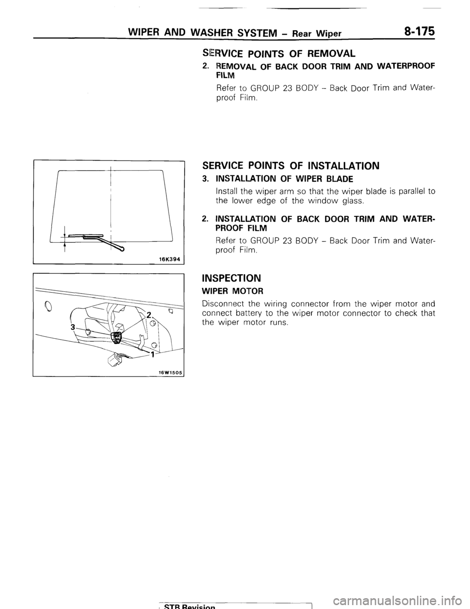
3. INSTALLATION OF WIPER BLADE
Install the wiper arm so that the wiper blade is parallel to
the lower edge of the window glass.
2. INSTALLATION OF BACK DOOR TRIM AND WATER-
PROOF FILM
Refer to GROUP 23 BODY - Back Door Trim and Water-
proof Film.
INSPECTION
WIPER MOTOR
Disconnect the wiring connector from the wiper motor and
connect battery to the wiper motor connector to check that
the wiper motor runs.
I STB Revision