Page 1374 of 1865
1 0 OIL PUMP
2WS (Diesel engine, with CX)
r.a-11 N-m (0-8—1.1 m-kg. 5.8—8.0 tt-lb)
7.8—11 Nm (0,8—1.1 m-kg, 5.8—8.0 ft-lb)
7.8—11 Nm (0.8-1.1 m-kg, 5.8-8.0 ft-lb)
C3DSP-J
39-59 N-m (ED (4,0—6.0 m-kg, (7) ZB—43 ft-lb)
49—59 N m (5.0—6.0 m-kg, 36—43 ft-lb)
37—62 N-m (3.8—S.3 m-kg, 27—38 ft-lb)
76G10X-017
1. Drive belt cover
2. Belt
3. Cooling fan
4. Intake air pipe
5. Nut
6. Oil pump pulley
7. Pipes
8. Bolt
9. Starter
10. Bolt
Removal Note
Oil pump (2WS Diesel engine)
1. Hold the oil pump pulley with the SST, and remove
the pulley nut.
2. Slide the pulley forward. Remove the hose, pipes,
and the pump. 3. Remove the pulley.
76G10X-018
10—86
Page 1377 of 1865
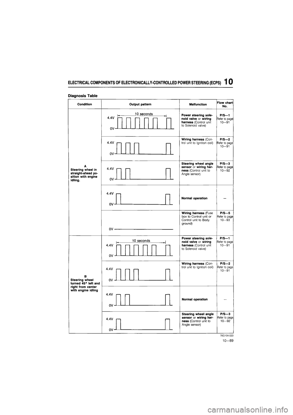
ELECTRICAL COMPONENTS OF ELECTRONICALLY-CONTROLLED POWER STEERING (ECPS) 1 0
Diagnosis Table
Condition Output pattern Malfunction Flow chart
No.
4.4V
0V-
10 seconds Power steering sole-noid valve or wiring harness (Control unit to Solenoid valve)
P/S—1
Refer to page
10-91
4.4V
0V-
Wiring harness (Con-
trol unit to Ignition coil) P/S—2 Refer to page 10-91
Steering wheel in straight-ahead po-sition with engine idling.
4.4V
OV-
Steering wheel angle sensor or wiring har-ness (Control unit to Angle sensor)
P/S—3 Refer to page 10-92
4.4V
ov-
Normal operation
Wiring harness (Fuse box to Control unit or Control unit to Body ground)
P/S—5 Refer to page 10—93
OV
10 seconds Power steering sole-
noid valve or wiring
harness (Control unit
to Solenoid valve)
P/S—1 Refer to page 10—91
B Steering wheel turned 45° left and right from center with engine idling
4.4V
0V
Wiring harness (Con-
trol unit to Ignition coil)
P/S—2 Refer to page 10-91
4.4V
0V'
Normal operation
4.4V
0V-
Steering wheel angle
sensor or wiring har-
ness (Control unit to
Angle sensor)
P/S—3 Refer to page 10—92
76G10X-023
10-89
Page 1378 of 1865
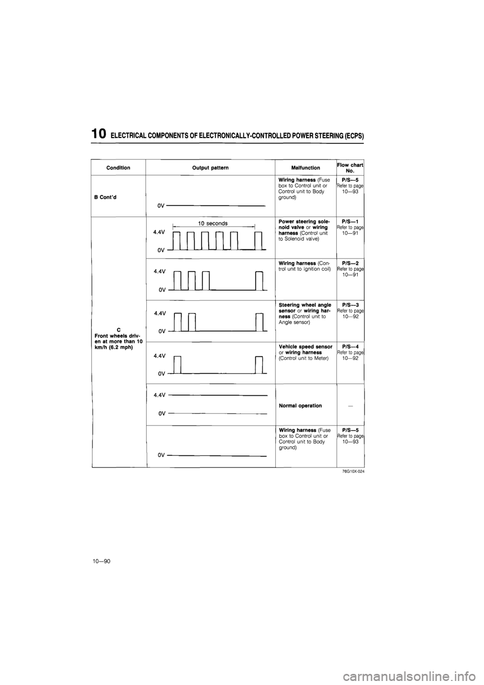
1 0 ELECTRICAL COMPONENTS OF ELECTRONICALLY-CONTROLLED POWER STEERING (ECPS)
Condition Output pattern Malfunction Flow chart No.
B Cont'd
OV
Wiring harness (Fuse
box to Control unit or
Control unit to Body
ground)
P/S—5 Refer to page 10-93
C
Front wheels driv-en at more than 10 km/h (6.2 mph)
4.4V —
1 3 s econds Power steering sole-noid valve or wiring harness (Control unit to Solenoid valve)
P/S—1 Refer to page 10-91
C
Front wheels driv-en at more than 10 km/h (6.2 mph)
uv
Power steering sole-noid valve or wiring harness (Control unit to Solenoid valve)
P/S—1 Refer to page 10-91
C
Front wheels driv-en at more than 10 km/h (6.2 mph)
4.4V
n\i
—
Wiring harness (Con-trol unit to Ignition coil) P/S—2 Refer to page 10-91
C
Front wheels driv-en at more than 10 km/h (6.2 mph)
Wiring harness (Con-trol unit to Ignition coil) P/S—2 Refer to page 10-91
C
Front wheels driv-en at more than 10 km/h (6.2 mph)
4.4V
Steering wheel angle sensor or wiring har-ness (Control unit to Angle sensor)
P/S-3 Refer to page 10—92
C
Front wheels driv-en at more than 10 km/h (6.2 mph)
V
Steering wheel angle sensor or wiring har-ness (Control unit to Angle sensor)
P/S-3 Refer to page 10—92
C
Front wheels driv-en at more than 10 km/h (6.2 mph)
4.4V
Vehicle speed sensor or wiring harness
(Control unit to Meter)
P/S—4 Refer to page 10-92
C
Front wheels driv-en at more than 10 km/h (6.2 mph)
uv
Vehicle speed sensor or wiring harness
(Control unit to Meter)
P/S—4 Refer to page 10-92
C
Front wheels driv-en at more than 10 km/h (6.2 mph)
4.4V
OV —
Normal operation —
C
Front wheels driv-en at more than 10 km/h (6.2 mph)
OV
Wiring harness (Fuse box to Control unit or Control unit to Body ground)
P/S—5 Refer to page 10-93
76G10X-024
10-90
Page 1379 of 1865
ELECTRICAL COMPONENTS
OF
ELECTRONICALLY-CONTROLLED POWER STEERING (ECPS) 1 0
Flow Chart
P/S—1
Failure of solenoid valve or wiring harness (Control unit to Solenoid valve)
Disconnect control unit connector. Check resistance between terminals.
Check voltage between (YL) and D (B) terminal of
control unit connector with engine running
OK
Terminal Resistance
M(LB)—N(LG) 3.5 — 7Q
Check control unit connector, solenoid valve connec-tor, and joint connector for connection, and check output pattern again.
NG
Check the solenoid valve (Refer to page 10—93),
NG
Replace solenoid valve.
P/S-Z Broken wiring harness
(Control unit to Coil)
Terminate of control unit connector with engine running.
NG
Replace control unit.
OK Repair wiring harness (Control unit to Solenoid valve).
Terminal Voltage
L(YL)-D(B) Approx. 12V
NG Repair the wiring harness (Control unit to Ignition
coil).
OK
Replace control unit.
76G10X-025
10—91
Page 1385 of 1865
ELECTRICAL COMPONENTS OF 4-WHEEL STEERING 1 0
Warning light output pattern Malfunction Flow chart No.
ON
ncc
Stepper motor or wiring harness 4WS—6 Stepper motor or wiring harness 4WS—6
ON
r\cc
Oil leakage or oil
level switch
4WS—7 Oil leakage or oil
level switch
4WS—7
ON
OFF
Control unit 4WS—8 Control unit 4WS—8
ON
ncc
Control unit, alter-nator, or wiring harness
4WS—9
ON
ncc
Control unit, alter-nator, or wiring harness
4WS—9 Control unit, alter-nator, or wiring harness
4WS—9
86U10X-226
10—97
Page 1391 of 1865
ELECTRICAL COMPONENTS OF 4-WHEEL STEERING 1 0
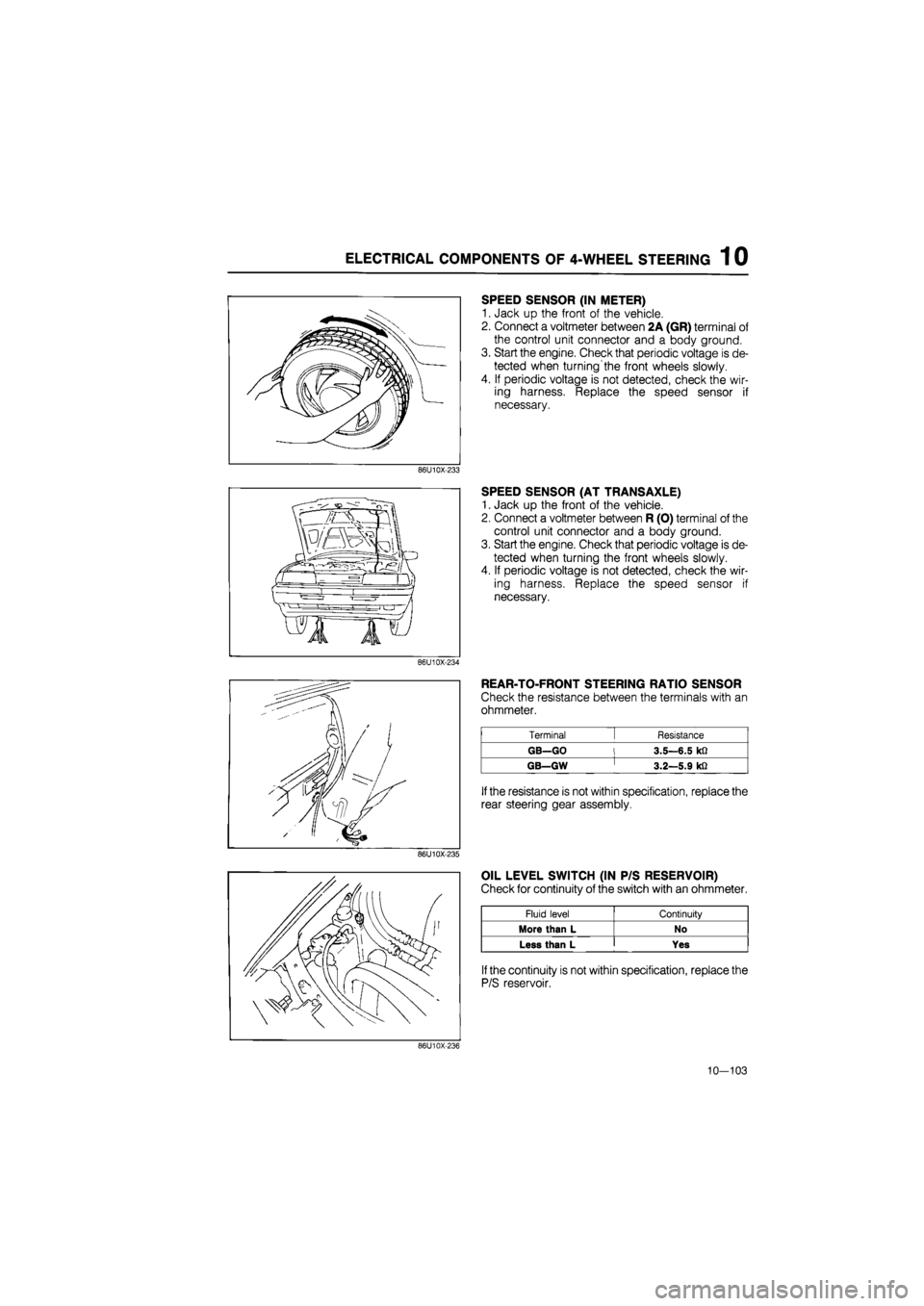
SPEED SENSOR (IN METER)
1. Jack up the front of the vehicle.
2. Connect a voltmeter between 2A (GR) terminal of
the control unit connector and a body ground.
3. Start the engine. Check that periodic voltage is de-
tected when turning'the front wheels slowly.
4. If periodic voltage is not detected, check the wir-
ing harness. Replace the speed sensor if
necessary.
86U10X-233
SPEED SENSOR (AT TRANSAXLE)
1. Jack up the front of the vehicle.
2. Connect a voltmeter between R (O) terminal of the
control unit connector and a body ground.
3. Start the engine. Check that periodic voltage is de-
tected when turning the front wheels slowly.
4. If periodic voltage is not detected, check the wir-
ing harness. Replace the speed sensor if
necessary.
86U10X-234
REAR-TO-FRONT STEERING RATIO SENSOR
Check the resistance between the terminals with an
ohmmeter.
Terminal [ Resistance
GB—GO l 3.5—6.5 kfi
GB—GW ' 3.2—5.9 kfi
If
the resistance is not within specification, replace the
rear steering gear assembly.
86U10X-235
OIL LEVEL SWITCH (IN P/S RESERVOIR)
Check for continuity of the switch with an ohmmeter.
Fluid level Continuity
More than L No
Less than L Yes
If
the continuity is not within specification, replace the
P/S reservoir.
86U10X-236
10—103
Page 1397 of 1865
TROUBLESHOOTING GUIDE 1 1
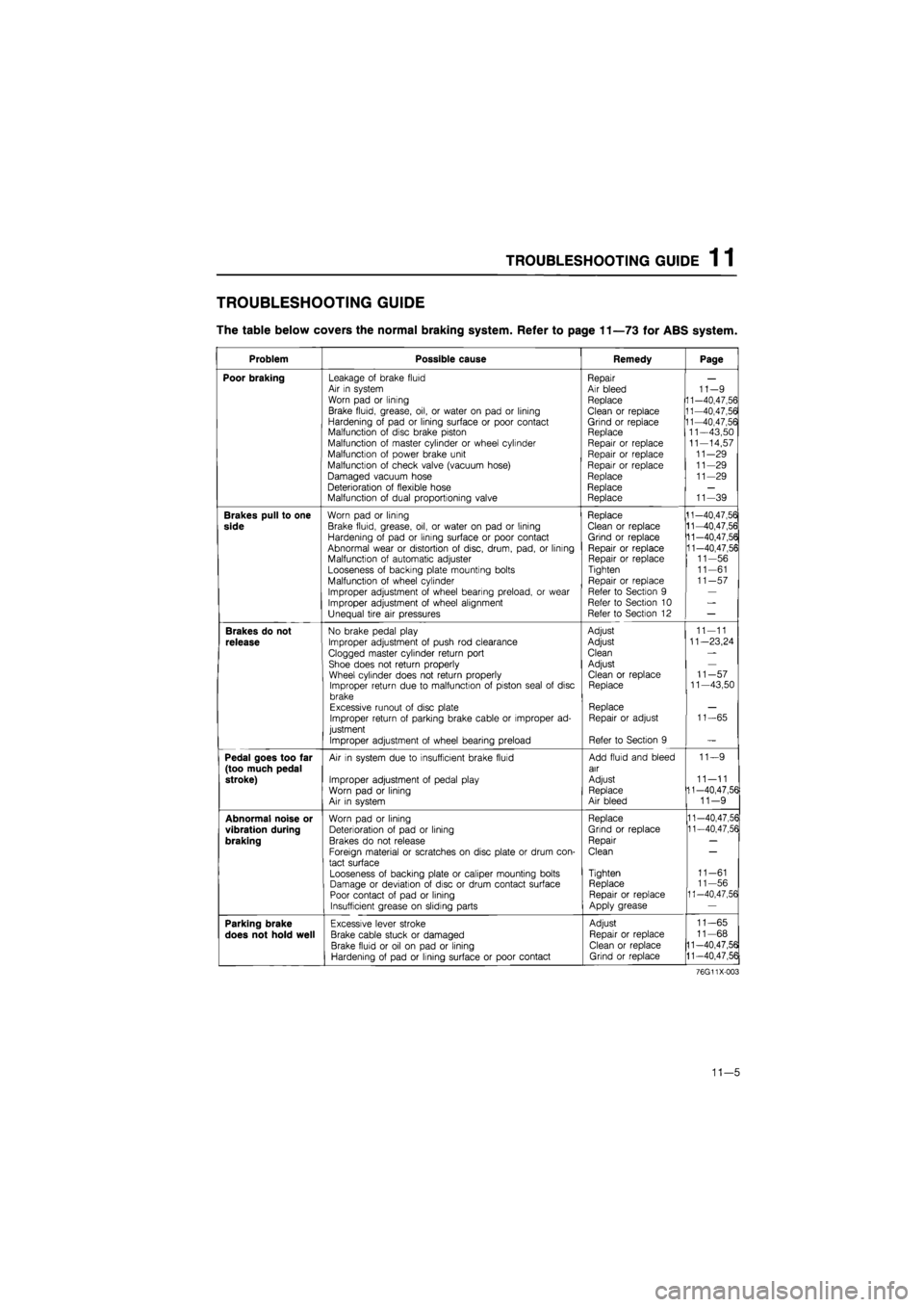
TROUBLESHOOTING GUIDE
The table below covers the normal braking system. Refer to page 11—73 for ABS system.
Problem Possible cause Remedy Page
Poor braking Leakage of brake fluid Air in system Worn pad or lining
Brake fluid, grease, oil, or water on pad or lining Hardening of pad or lining surface or poor contact Malfunction of disc brake piston Malfunction of master cylinder or wheel cylinder Malfunction of power brake unit
Malfunction of check valve (vacuum hose)
Damaged vacuum hose Deterioration of flexible hose Malfunction of dual proportioning valve
Repair Air bleed Replace
Clean or replace Grind or replace Replace Repair or replace Repair or replace Repair or replace Replace Replace Replace
11-9 11-40,47,56 11-40,47,56 11-40,47,56 11—43,50 11-14,57 11-29 11-29 11-29
11-39
Brakes pull to one
side
Worn pad or lining
Brake fluid, grease, oil, or water on pad or lining Hardening of pad or lining surface or poor contact Abnormal wear or distortion of disc, drum, pad, or lining Malfunction of automatic adjuster Looseness of backing plate mounting bolts Malfunction of wheel cylinder
Improper adjustment of wheel bearing preload, or wear Improper adjustment of wheel alignment Unequal tire air pressures
Replace Clean or replace Grind or replace Repair or replace Repair or replace Tighten
Repair or replace Refer to Section 9 Refer to Section 10 Refer to Section 12
11-40,47,56 11-40,47,56 11-40,47,56 11-40,47,56 11-56 11-61 11-57
Brakes do not
release
No brake pedal play
Improper adjustment of push rod clearance
Clogged master cylinder return port Shoe does not return properly Wheel cylinder does not return properly Improper return due to malfunction of piston seal of disc brake Excessive runout of disc plate Improper return of parking brake cable or improper ad-justment
Improper adjustment of wheel bearing preload
Adjust
Adjust
Clean
Adjust Clean or replace Replace
Replace Repair or adjust
Refer to Section 9
11-11
11—23,24
11-57 11—43,50
11-65
Pedal goes too far (too much pedal stroke)
Air in system due to insufficient brake fluid
Improper adjustment of pedal play Worn pad or lining Air in system
Add fluid and bleed air
Adjust Replace Air bleed
11—9
11—11 11-40,47,56 11-9
Abnormal noise or
vibration during
braking
Worn pad or lining Deterioration of pad or lining Brakes do not release
Foreign material or scratches on disc plate or drum con-tact surface
Looseness of backing plate or caliper mounting bolts Damage or deviation of disc or drum contact surface Poor contact of pad or lining Insufficient grease on sliding parts
Replace
Grind or replace
Repair
Clean
Tighten Replace Repair or replace Apply grease
11-40,47,56 11-40,47,56
11-61 11-56 11-40,47,56
Parking brake
does not hold well
Excessive lever stroke
Brake cable stuck or damaged
Brake fluid or oil on pad or lining Hardening of pad or lining surface or poor contact
Adjust
Repair or replace Clean or replace Grind or replace
11-65
11-68
11-40,47,56
11-40,47,56
76G11X-003
11—5
Page 1423 of 1865
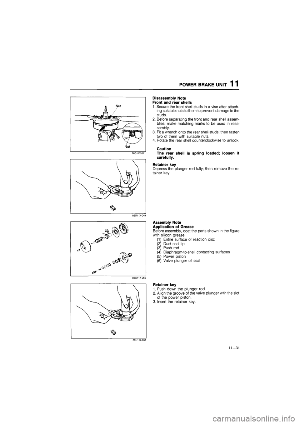
POWER BRAKE UNIT 1 1
76G11X-071
Disassembly Note
Front and rear shells
1. Secure the front shell studs in a vise after attach-
ing suitable nuts to them to prevent damage to the
studs.
2. Before separating the front and rear shell assem-
blies, make matching marks to be used in reas-
sembly.
3. Fit a wrench onto the rear shell studs; then fasten
two of them with suitable nuts.
4. Rotate the rear shell counterclockwise to unlock.
Caution
The rear shell is spring loaded; loosen it
carefully.
Retainer key
Depress the plunger rod fully; then remove the re-
tainer key.
86U11X-049
86U11X-050
Assembly Note
Application of Grease
Before assembly, coat the parts shown in the figure
with silicon grease.
(1) Entire surface of reaction disc
(2) Dust seal lip
(3) Push rod
(4) Diaphragm-to-shell contacting surfaces
(5) Power piston
(6) Valve plunger oil seal
Retainer key
1. Push down the plunger rod.
2. Align the groove of the valve plunger with the slot
of the power piston.
3. Insert the retainer key.
86U11X-051
11—31