Page 1427 of 1865
VACUUM PUMP 1 1
VACUUM PUMP
1. Disconnect the vacuum hose and release the re-
maining vacuum.
2. Connect a vacuum gauge as shown in the figure.
3. Run the engine at idle speed.
Idle speed: 720 1 20 rpm
4. Check that the vacuum reaches 500 mmHg (19.7
inHg) in 8 seconds or less.
5. Check that the maximum vacuum is within approx.
700—720 mmHg (27.6—28.3 inHg) in 80 sec-
onds or less.
REMOVAL AND INSTALLATION
1. Remove in the sequence shown in the figure.
2. Install in the reverse order of removal, referring to installation note for specially marked parts.
Note
The engine oil will leak out when disconnecting the oil hose. Prepare a suitable container
for it to drain into.
76G11X-038
76G11X-037
1. Vacuum hose
2. Oil return hose
3. Oil inlet hose
4. Drive velt cover
5. Vacuum pump
Page 1437 of 1865
FRONT DISC BRAKE 1 1
INSPECTION
Check the following and replace any faulty parts.
Disc Pad
1. Oil or grease on facing
2. Abnormal wear or cracks
3. Deterioration or heat damage 4. Remaining lining thickness
Thickness: 2.0 mm (0.08 in) min.
86U11X079
Disc Plate
1. Runout
Runout: 0.1 mm (0.004 in) max.
Caution
a) There must be no wheel bearing looseness.
b) Measure at the outer edge of the disc plate
surface.
86U11X-080
2. Wear or damage
Thickness specifications:
mm (in)
Standard Minimum
13 inch-wheel 20 (0.79) 18 (0.71)
14 or 15 inch-wheel 24 (0.94) 22 (0.86)
76G11X-046
11-45
Page 1446 of 1865
1 1 REAR DISC BRAKE
INSPECTION
Check the following and replace or repair any faulty
parts.
Disc Pad
1. Oil or grease on facing
2. Abnormal wear or cracks
3. Deterioration or heat damage
4. Remaining lining thickness
Thickness: 1 mm (0.04 in) min.
76G11X-086
Disc Plate
1. Runout
Runout: 0.1 mm (0.004 in) max.
Caution
a) There must be no wheel bearing looseness.
b) Measure at the outer edge of the disc plate
surface.
86U11X-104
2. Wear or damage
Thickness
Standard: 10 mm (0.39 in)
Minimum: 8 mm (0.31 in)
86U11X-105
11—54
Page 1496 of 1865
WHEELS AND TIRES 1 2
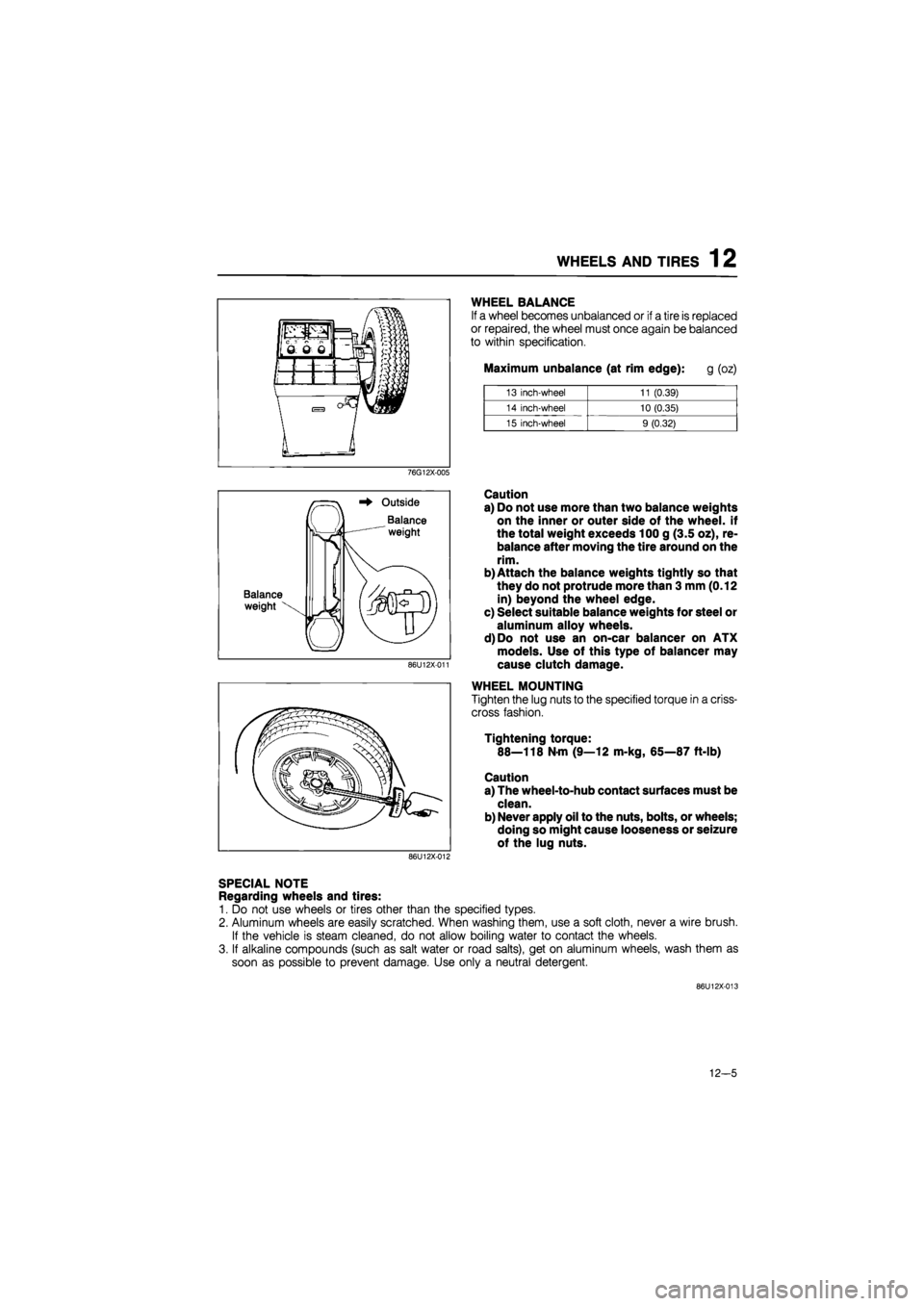
WHEEL BALANCE
If a wheel becomes unbalanced or if a tire is replaced
or repaired, the wheel must once again be balanced
to within specification.
Maximum unbalance (at rim edge): g (oz)
13 inch-wheel 11 (0.39)
14 inch-wheel 10 (0.35)
15 inch-wheel 9 (0.32)
76G12X-005
Balance
weight
Outside
Balance
weight
86U12X-011
Caution
a) Do not use more than two balance weights
on the inner or outer side of the wheel, if
the total weight exceeds 100 g (3.5 oz), re-
balance after moving the tire around on the
rim.
b) Attach the balance weights tightly so that
they do not protrude more than 3 mm (0.12
in) beyond the wheel edge.
c) Select suitable balance weights for steel or
aluminum alloy wheels.
d)Do not use an on-car balancer on ATX
models. Use of this type of balancer may
cause clutch damage.
WHEEL MOUNTING
Tighten the lug nuts to the specified torque in a criss-
cross fashion.
Tightening torque:
88—118 N-m (9—12 m-kg, 65—87 ft-lb)
Caution
a) The wheel-to-hub contact surfaces must be
clean.
b) Never apply oil to the nuts, bolts, or wheels;
doing so might cause looseness or seizure
of the lug nuts.
86U12X-012
SPECIAL NOTE
Regarding wheels and tires:
1. Do not use wheels or tires other than the specified types.
2. Aluminum wheels are easily scratched. When washing them, use a soft cloth, never a wire brush.
If the vehicle is steam cleaned, do not allow boiling water to contact the wheels.
3. If alkaline compounds (such as salt water or road salts), get on aluminum wheels, wash them as
soon as possible to prevent damage. Use only a neutral detergent.
86U12X-013
12-5
Page 1501 of 1865
13 OUTLINE
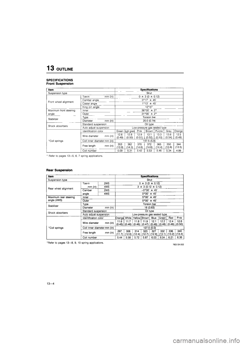
SPECIFICATIONS
Front Suspension
Item Specifications
Suspension type Strut
Toe-in mm (in) 0 ± 3 (0 ± 0.12)
Front wheel alignment Camber angle 0C 17' ± 45' Front wheel alignment Caster angle 1c 13' ± 45'
King pin angle 12°47'
Maximum front steering Inner 36 °00' ± 2°
angle Outer 31 °00' ± 2°
Stabilizer Type Torsion bar Stabilizer Diameter mm (in) 20.0 (0.79)
Shock absorbers Standard suspension Oil type Shock absorbers Auto adjust suspension Low-pressure gas sealed type
Identification color Green Light green Pink Brown Purple Gray Orange
Wire diameter mm (in) 12.6 (0.49) 12.8 (0.50)
12.9
(0.51) 13.1 (0.52)
13.3 (0.53)
13.6
(0.54) 12.5 (0.49)
*Coil springs Coil inner diameter mm (in) 147.5 (5.8)
Free length mm (in) 353 (13.9)
362 (14.3) 370 (14.6) 372 (14.6) 365 (14.4)
350
(13.8)
344
(13.5)
Coil number 5.09 5.31 5 42 5.53 5.46 5.34 4.99
* Refer to pages 13—5, 6, 7 spring applications.
Rear Suspension
Item Specifications
SusDension tvDe Strut
Rear wheel alignment
Toe-in
mm (in)
2WS 0 ± 3 (0 ± 0.12)
Rear wheel alignment
Toe-in
mm (in) 4WS 3 ± 3 (0.12 ± 0.12) Rear wheel alignment Camber
anale
2WS -0°30' ± 45' Rear wheel alignment Camber
anale 4WS 0°00' ± 45'
Maximum rear steering angle (4WS) Inner 5°00' ± 45' Maximum rear steering angle (4WS) Outer 5°00' ± 45'
Stabilizer TvDe Torsion bar Stabilizer Diameter mm (in) 16 (0.63)
Shock absorbers Standard susDension Oil tvDe Shock absorbers Auto adiust suspension Low-pressure c las sealed type
'Coil springs
Identification color Orange White Yellow Brown Blue Green Red Pink
'Coil springs
Wire diameter mm (in) 11.6
(0.45)
11.7 (0.46) 11.8
(0.46)
11.9 (0.47)
12.1
(0.48)
12.2
(0.48)
12.4 (0.49) 12.6 (0.50)
'Coil springs Coil inner diameter mm (in) 127.5 (5.0) 'Coil springs
Free length mm (in) 297 (11.7) 306 (12.0)
314 (12.4) 323 (12.7) 327 (12.9) 332 (13.1) 336 (13.21 340 (13.4)
'Coil springs
Coil number 5.44 5.58 5.72 5.87 6.03 6.04 6.21 6.36
'Refer to pages 13—8, 9, 10 spring applications.
13—4
Page 1502 of 1865
OUTLINE 13
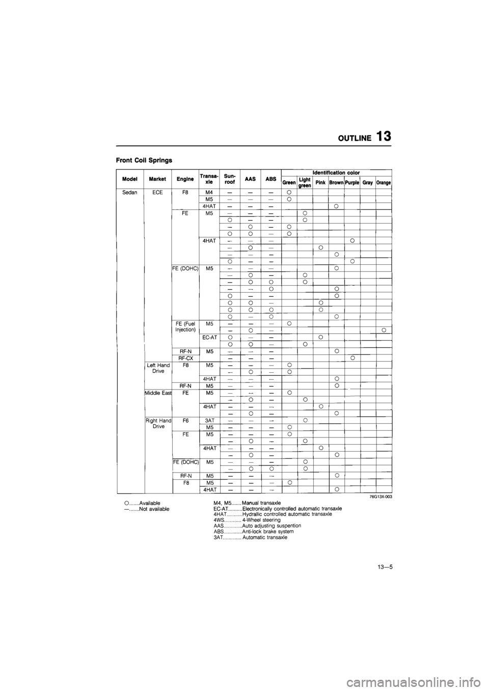
Front Coil Springs
Transa-
xle
Sun-
roof
Identification color
Model Market Engine Transa-
xle
Sun-
roof AAS ABS Green Light
green Pink Brown Purple Gray Orange
Sedan ECE F8 M4 — — — O
M5 — — — 0
4HAT — — — O
FE M5 — — — O
0 — — O
— o — o
o o — o
4HAT -— — o
— o — O
— — — o
o — — o
FE (DOHC) M5 — — — o
— o — 0
— o o o
— — o o
0 — — o
o o — o
0 0 o o
o — 0 o
FE (Fuel M5 — — — o
Injection) — 0 — O
EC-AT O — — o
o o — o
RF-N M5 — — — 0
RF-CX — — — o
Left Hand F8 M5 — — — o
Drive „ o — o
4HAT — — — o
RF-N M5 — — — o
Middle East FE M5 — — — o
-o — o
4HAT — — — o
— o — 0
Right Hand F6 3AT — — — 0
Drive M5 — — — o
FE M5 — — — 0
— o _ o
4HAT — — — o
— 0 — o
FE (DOHC) M5 — — — o
— o o 0
RF-N M5 — — — o
F8 M5 — — — 0
4HAT — — — o
76G13X003
O Available M4, M5.... ...Manual transaxle
— Not available EC-AT ....Electronically controlled automatic transaxle 4HAT ....Hydrallic controlled automatic transaxle
4WS ... 4-Wheel steering
AAS ....Auto adjusting suspention ABS ....Anti-lock brake system
3AT ... Automatic transaxle
13—5
Page 1505 of 1865
13 OUTLINE
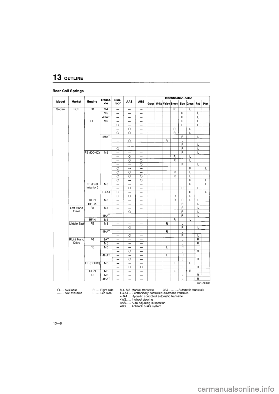
Rear Coil Springs
Transa-xle
Sun-
roof
Identification color
Model Market Engine Transa-xle
Sun-
roof AAS ABS Orange White Yellow Brown Blue Green Red Pink
Sedan ECE F8 M4 — — — R L
M5 — — — R L
4HAT — — R L
FE M5 — — — R L
— — R L
— o — R L
O 0 — R L
4HAT — „ — R L
— 0 — R L
— — — R L
o — — R L
FE (DOHC) M5 — — — R L
— o — R L
— o 0 R L
— — o R L
0 — — R L
0 o — R L
o 0 0 R L
o — o R L
FE (Fuel M5 — — — R L
Injection) — o — R L
EC-AT o — — R L
o o — R L
RF-N M5 — — — R R L L
RF-CX _ — — R L
Left Hand F8 M5 — — — R L
Drive — o — R L
4HAT — — — R L
RF-N M5 — — — R L
Middle East FE M5 — — — R L
— o — n L
4HAT — — — R L
— o — L
Right Hand F6 3AT — — — L R
Drive M5 — — — L R
FE M5 — — — L
— o — L R
4HAT — — — L
— o — L R
FE (DOHC) M5 — — — L R — o o L R
RF-N M5 — — L R
F8 M5 — — — L R
4HAT — — — L R
76G13X-006
0 Available R Right side M4, M5 Manual transaxle 3AT Automatic transaxle — Not available L Left side EC-AT... Electronically controlled automatic transaxle 4HAT..., Hydrallic controlled automatic transaxle 4WS...... 4-wheef steering AAS Auto adjusting suspention ABS Anti-lock brake system
13-8
Page 1508 of 1865
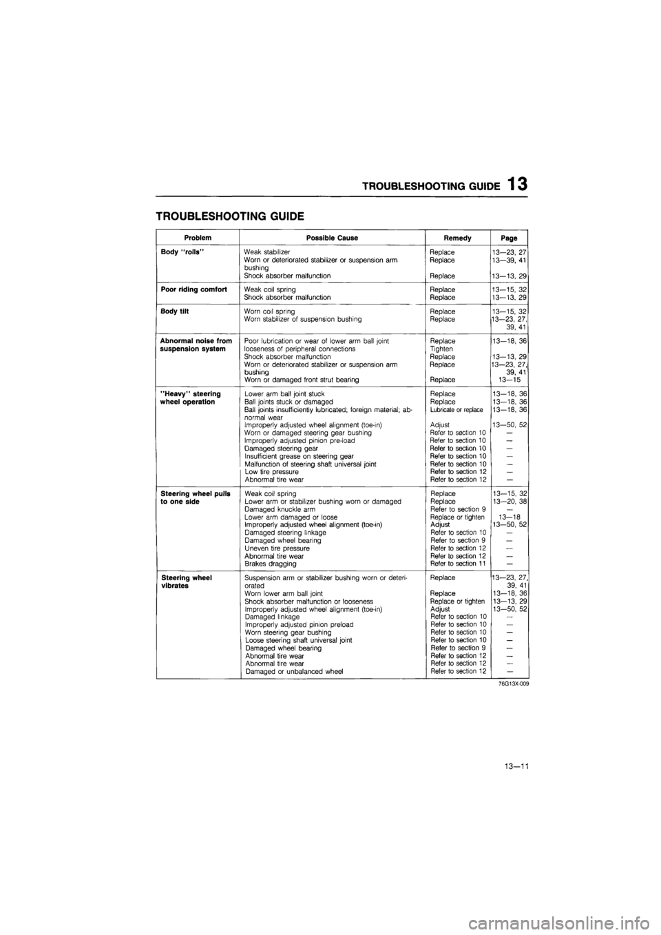
TROUBLESHOOTING GUIDE 1 3
TROUBLESHOOTING GUIDE
Problem Possible Cause Remedy Page
Body "rolls" Weak stabilizer Replace 13-23, 27 Worn or deteriorated stabilizer or suspension arm Replace 13—39, 41 bushing
Shock absorber malfunction Replace 13-13, 29
Poor riding comfort Weak coil spring Replace 13-15, 32 Shock absorber malfunction Replace 13-13. 29
Body tilt Worn coil spring Replace 13-15, 32 Worn stabilizer of suspension bushing Replace 13-23, 27,
39, 41
Abnormal noise from Poor lubrication or wear of lower arm ball joint Replace 13-18, 36 suspension system looseness of peripheral connections Tighten
Shock absorber malfunction Replace 13-13, 29 Worn or deteriorated stabilizer or suspension arm Replace 13—23, 27, bushing 39, 41 Worn or damaged front strut bearing Replace 13-15
"Heavy" steering Lower arm ball joint stuck Replace 13—18, 36
wheel operation Ball joints stuck or damaged Replace 13-18, 36
Ball joints insufficiently lubricated; foreign material; ab-Lubricate or replace 13-18, 36
normal wear Improperly adjusted wheel alignment (toe-in) Adjust 13-50, 52
Worn or damaged steering gear bushing Refer to section 10 —
Improperly adjusted pinion pre-load Refer to section 10 —
Damaged steering gear Refer to section 10 —
Insufficient grease on steering gear Refer to section 10 —
Malfunction of steering shaft universal joint Refer to section 10 —
Low tire pressure Refer to section 12 —
Abnormal tire wear Refer to section 12 —
Steering wheel pulls Weak coil spring Replace 13-15, 32
to one side Lower arm or stabilizer bushing worn or damaged Replace 13-20, 38
Damaged knuckle arm Refer to section 9 —
Lower arm damaged or loose Replace or tighten 13-18 Improperly adjusted wheel alignment (toe-in) Adjust 13-50, 52
Damaged steering linkage Refer to section 10 —
Damaged wheel bearing Refer to section 9 —
Uneven tire pressure Refer to section 12 —
Abnormal tire wear Refer to section 12 —
Brakes dragging Refer to section 11 —
Steering wheel Suspension arm or stabilizer bushing worn or deteri-Replace 13—23, 27.
vibrates orated 39, 41
Worn lower arm ball joint Replace 13-18, 36
Shock absorber malfunction or looseness Replace or tighten 13-13, 29
Improperly adjusted wheel alignment (toe-in) Adjust 13-50, 52 Damaged linkage Refer to section 10
Improperly adjusted pinion preload Refer to section 10
Worn steering gear bushing Refer to section 10 —
Loose steering shaft universal joint Refer to section 10 —
Damaged wheel bearing Refer to section 9 —
Abnormal tire wear Refer to section 12 —
Abnormal tire wear Refer to section 12 —
Damaged or unbalanced wheel Refer to section 12 —
76G13X-009
13—11