Page 1792 of 1865
OUTLINE 16
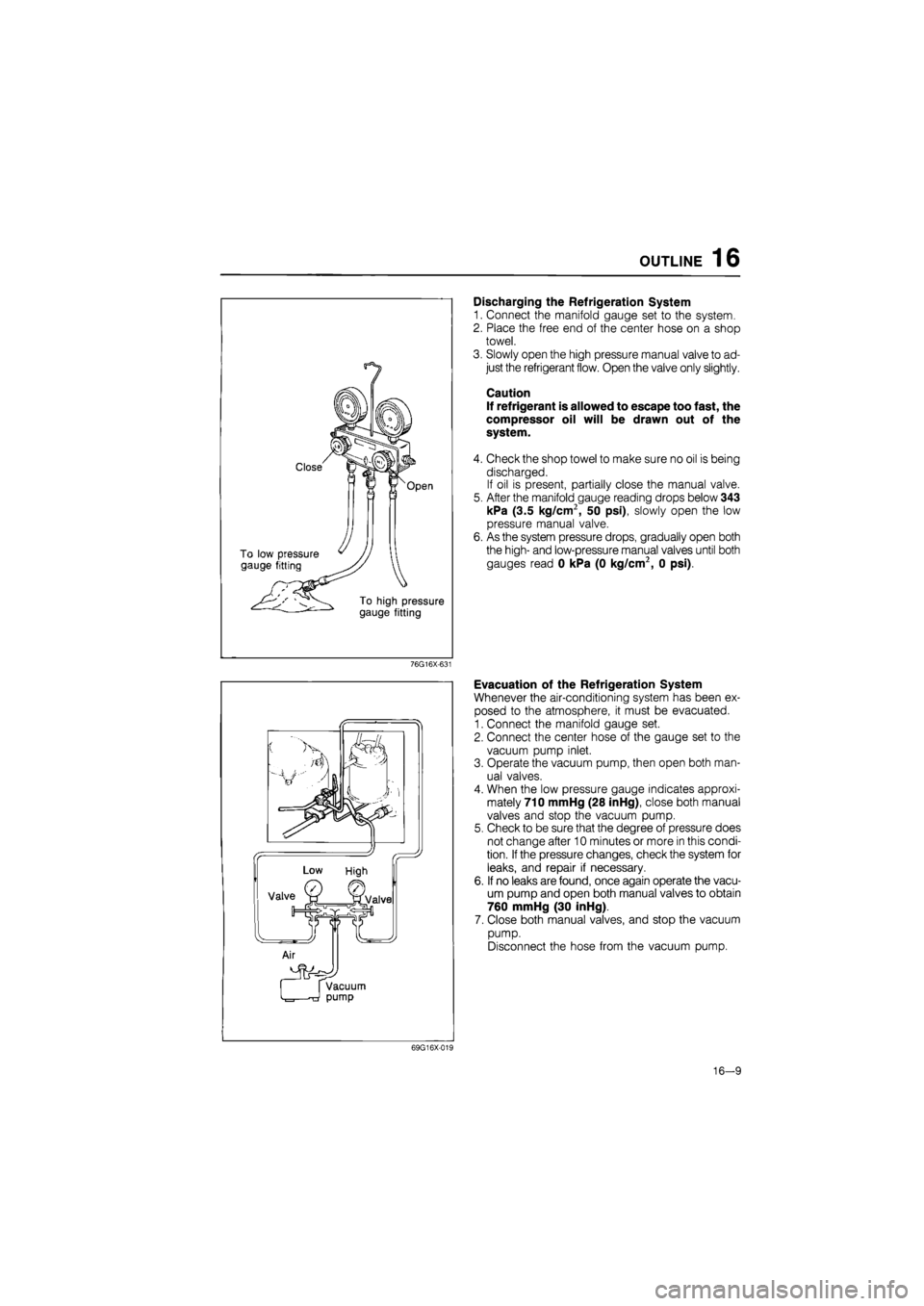
Discharging the Refrigeration System
1. Connect the manifold gauge set to the system.
2. Place the free end of the center hose on a shop
towel.
3. Slowly open the high pressure manual valve to ad-
just the refrigerant flow. Open the valve only slightly.
Caution
If refrigerant is allowed to escape too fast, the
compressor oil will be drawn out of the
system.
4. Check the shop towel to make sure no oil is being
discharged.
If oil is present, partially close the manual valve.
5. After the manifold gauge reading drops below 343
kPa (3.5 kg/cm2, 50 psi), slowly open the low
pressure manual valve.
6. As the system pressure drops, gradually open both
the high- and low-pressure manual valves until both
gauges read 0 kPa (0 kg/cm2, 0 psi).
76G16X-631
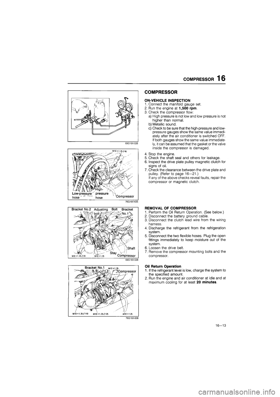
Evacuation of the Refrigeration System
Whenever the air-conditioning system has been ex-
posed to the atmosphere, it must be evacuated.
1. Connect the manifold gauge set.
2. Connect the center hose of the gauge set to the
vacuum pump inlet.
3. Operate the vacuum pump, then open both man-
ual valves.
4. When the low pressure gauge indicates approxi-
mately 710 mmHg (28 inHg), close both manual
valves and stop the vacuum pump.
5. Check to be sure that the degree of pressure does
not change after 10 minutes or more in this condi-
tion.
If
the pressure changes, check the system for
leaks, and repair if necessary.
6. If no leaks are found, once again operate the vacu-
um pump and open both manual valves to obtain
760 mmHg (30 inHg).
7. Close both manual valves, and stop the vacuum
pump.
Disconnect the hose from the vacuum pump.
69G16X-019
16-9
Page 1796 of 1865
COMPRESSOR 16
69G16X-026
M10X1.25^45
Low-pressure x pressure
hose hose Compressor
COMPRESSOR
ON-VEHICLE INSPECTION
1. Connect the manifold gauge set.
2. Run the engine at 1,500 rpm.
3. Check the compressor flow:
a) High pressure is not low and low pressure is not
higher than normal.
b) Metallic sound.
c) Check to be sure that the high-pressure and low-
pressure gauges show the same value immedi-
ately after the air conditioner is switched OFF.
If both gauges show the same value immediate-
ly, it can be assumed that the gasket or the valve
inside the compressor is damaged.
4. Stop the engine.
5. Check the shaft seal and others for leakage.
6. Inspect the drive plate pulley magnetic clutch for
signs of oil.
7. Check the clearance between the drive plate and
pulley. (Refer to page 16—21.)
If any of the above checks reveal faults, repair the
compressor or magnetic clutch.
76G16X-635
Bracket No.2 Adjusting Bolt Bracket
, ,shaft
' stay _ M8XI. 25^20 MIO X 1.25 Compressor
69G16X-028
REMOVAL OF COMPRESSOR
1. Perform the Oil Return Operation. (See below.)
2. Disconnect the battery ground cable.
3. Disconnect the clutch lead wire from the wiring
harness.
4. Discharge the refrigerant from the refrigeration
system.
5. Disconnect the two flexible hoses. Plug the open
fittings immediately to keep moisture out of the
system.
6. Loosen the drive belt.
7. Remove the compressor mounting bolts and the
compressor.
Bracket No.1 M
to* 1.25
^Compressor
MIOxl. 25^110 MIOxl. 25^125
Oil Return Operation
1. If the refrigerant level is low, charge the system to
the specified amount.
2. Run the engine and air conditioner at idle and at
maximum cooling for at least 20 minutes.
76G16X-636
16—13
Page 1797 of 1865
16 COMPRESSOR
1. Bolt
2. Drive plate
3. Shim
4. Snap ring
5. Cover
6. Pulley assembly
7. Screw
8. Coil
9. Felt
10. Shaft seal cover
11. Front cylinder head
12. Seal seat
13. Shaft seal
14. O-ring
15. Gasket
16. Valve plate
17. Suction valve
18. O-ring
19. Oil filler plug
20. O-ring
21. Drain plug
22. Plate
23. Bolt
24. Gasket
25. Bolt
69G16X-030
(f''
(
(f''
( 1 49 9201 010 H
/
flSt^
ISSP
, —*
76G16X-605
DISASSEMBLY OF MAGNETIC CLUTCH
1. Using the SST to prevent drive plate rotation, re-
move the center bolt.
2. Using the SST, remove the drive plate.
3. Remove the shims from either the drive shaft or
the drive plate.
76G16X-606
16—14
Page 1798 of 1865
COMPRESSOR 16
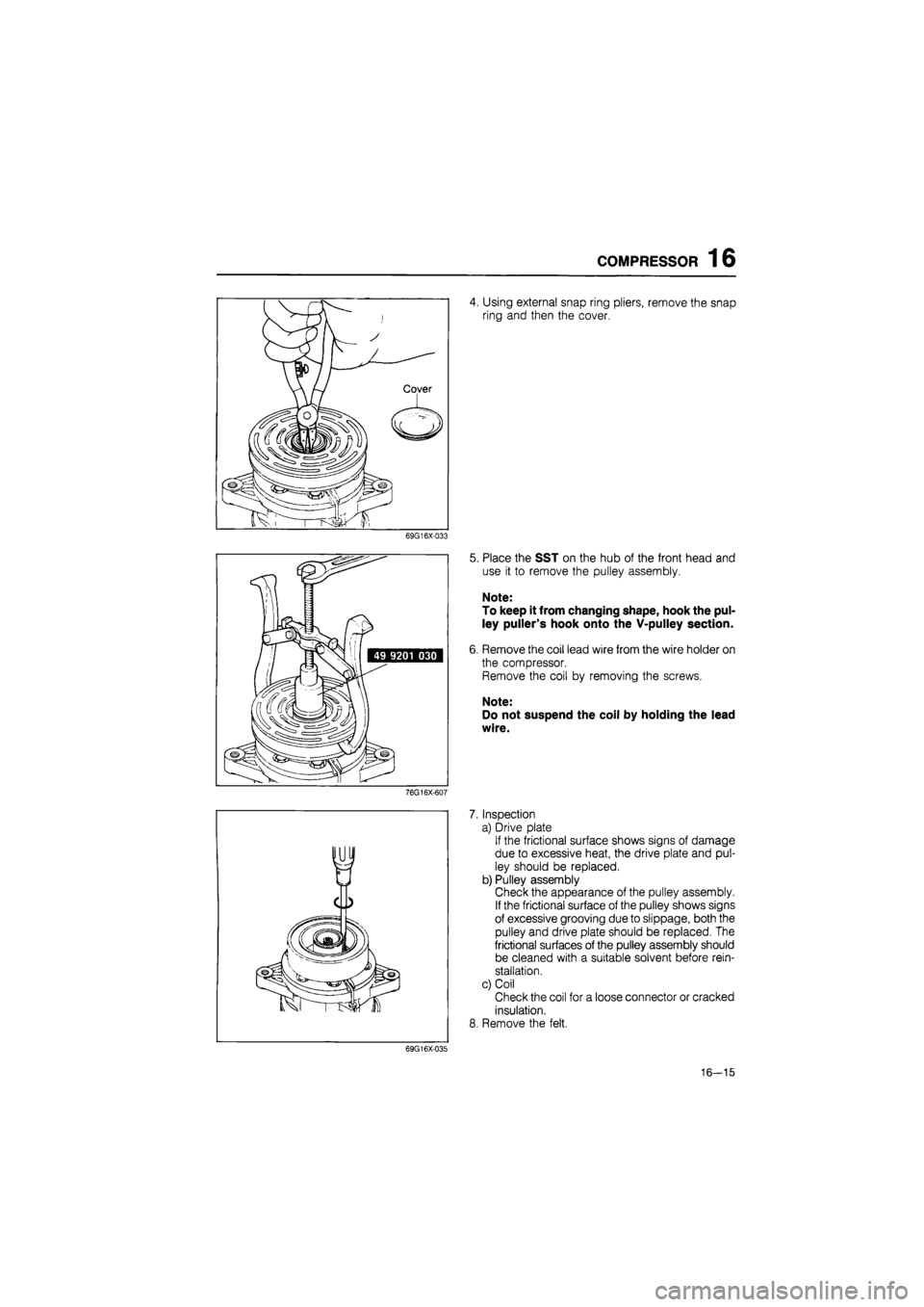
4. Using external snap ring pliers, remove the snap
ring and then the cover.
69G16X-033
7.
8.
69G16X-035
Place the SST on the hub of the front head and
use it to remove the pulley assembly.
Note:
To keep it from changing shape, hook the pul-
ley puller's hook onto the V-pulley section.
Remove the coil lead wire from the wire holder on
the compressor.
Remove the coil by removing the screws.
Note:
Do not suspend the coil by holding the lead
wire.
Inspection
a) Drive plate
If the frictional surface shows signs of damage
due to excessive heat, the drive plate and pul-
ley should be replaced.
b) Pulley assembly
Check the appearance of the pulley assembly.
If the frictional surface of the pulley shows signs
of excessive grooving due to slippage, both the
pulley and drive plate should be replaced. The
frictional surfaces of the pulley assembly should
be cleaned with a suitable solvent before rein-
stallation.
c) Coil
Check the coil for a loose connector or cracked
insulation.
Remove the felt.
16—15
Page 1799 of 1865
16 COMPRESSOR
DISASSEMBLY OF COMPRESSOR
Shaft Seal Assembly
1. Using the SST, remove the shaft seal cover as fol-
lows: attach the remover hook to the shaft seal cov-
er hook and draw the cover out slowly.
76G16X-608
Compressor Oil
1. Remove the drain plug and the oil filler plug, then
drain out the oil.
2. Measure the drained oil with a measuring cylinder.
3. Check the drained oil for any of the following con-
ditions:
a) Whether the opacity of the oil has increased.
b) Whether the oil color has changed to red.
c) Whether foreign matter, such as metal filings,
etc., is present in the oil.
Note:
If the oil drained from the compressor is as
described above, replaced it with new oil.
69G16X-037
16—16
Page 1801 of 1865
16 COMPRESSOR
76G16X-611
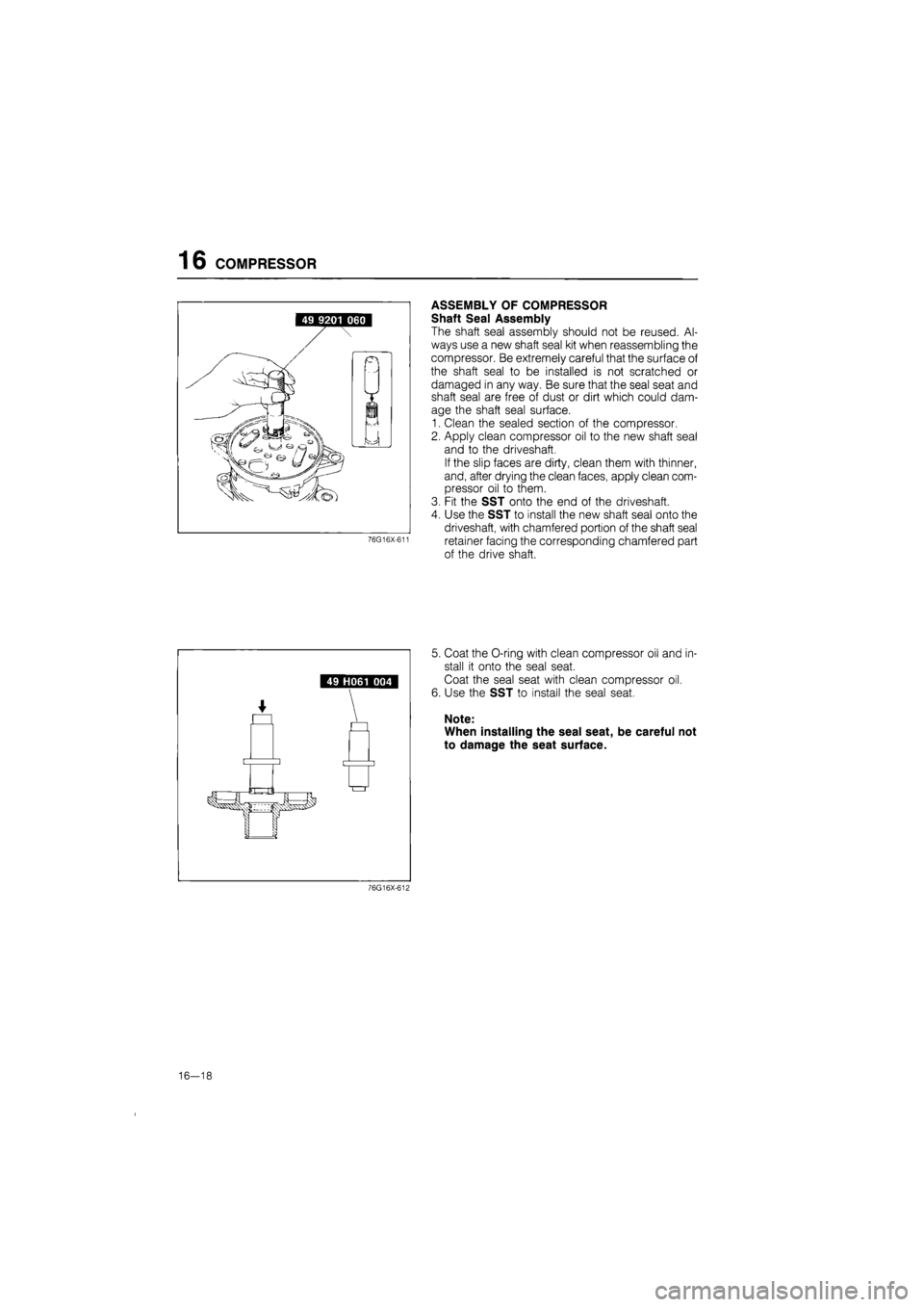
ASSEMBLY OF COMPRESSOR
Shaft Seal Assembly
The shaft seal assembly should not be reused. Al-
ways use a new shaft seal kit when reassembling the
compressor. Be extremely careful that the surface of
the shaft seal to be installed is not scratched or
damaged in any way. Be sure that the seal seat and
shaft seal are free of dust or dirt which could dam-
age the shaft seal surface.
1. Clean the sealed section of the compressor.
2. Apply clean compressor oil to the new shaft seal
and to the driveshaft.
If the slip faces are dirty, clean them with thinner,
and, after drying the clean faces, apply clean com-
pressor oil to them.
3. Fit the SST onto the end of the driveshaft.
4. Use the SST to install the new shaft seal onto the
driveshaft, with chamfered portion of the shaft seal
retainer facing the corresponding chamfered part
of the drive shaft.
5. Coat the O-ring with clean compressor oil and in-
stall it onto the seal seat.
Coat the seal seat with clean compressor oil.
6. Use the SST to install the seal seat.
Note:
When installing the seal seat, be careful not
to damage the seat surface.
76G16X-612
16-18
Page 1802 of 1865
COMPRESSOR 16
Escape groove
^ / / / / j / / ' / / / / /
' / / I / /
1 \ \ x Suction \ \ \/ valve
n W: \ / / y /
I u
Piston— ^
69G16X-044
69G16X-045
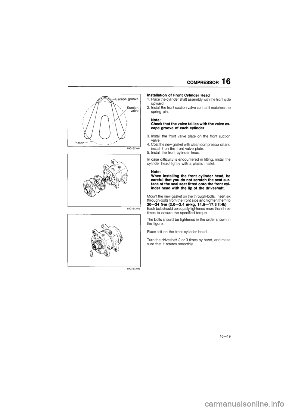
Installation of Front Cylinder Head
1. Place the cylinder shaft assembly with the front side
upward.
2. Install the front suction valve so that it matches the
spring pin.
Note:
Check that the valve tallies with the valve es-
cape groove of each cylinder.
3. Install the front valve plate on the front suction
valve.
4. Coat the new gasket with clean compressor oil and
install it on the front valve plate.
5. Install the front cylinder head.
In case difficulty is encountered in fitting, install the
cylinder head lightly with a plastic mallet.
Note:
When installing the front cylinder head, be
careful that you do not scratch the seat sur-
face of the seal seat fitted onto the front cyl-
inder head with the lip of the driveshaft.
Mount the new gasket on the through-bolts. Insert six
through-bolts from the front side and tighten them to
20—24 N m (2.0—2.4 m-kg, 14.5—17.3 ft-lb)
Each bolt should be equally tightened more than three
times to ensure the specified torque.
The bolts should be tightened in the order shown in
the figure.
Place felt on the front cylinder head.
Turn the driveshaft 2 or 3 times by hand, and make
sure that it rotates smoothly.
69G16X046
16—19
Page 1803 of 1865
16 COMPRESSOR
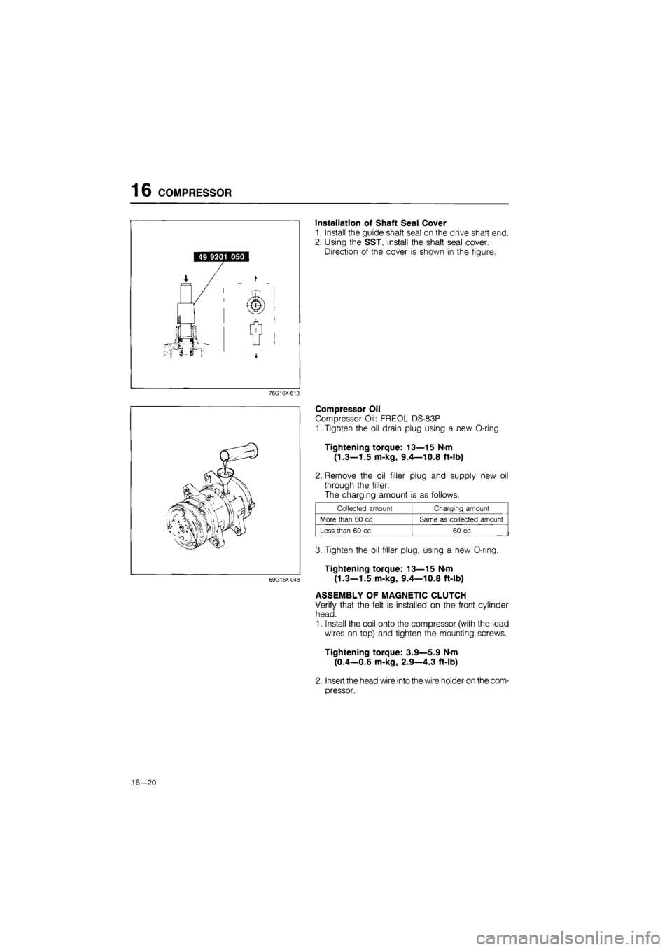
Installation of Shaft Seal Cover
1. Install the guide shaft seal on the drive shaft end.
2. Using the SST, install the shaft seal cover.
Direction of the cover is shown in the figure.
76G16X-613
69G16X-048
Compressor Oil
Compressor Oil: FREOL DS-83P
1. Tighten the oil drain plug using a new O-ring.
Tightening torque: 13—15 N-m
(1.3—1.5 m-kg, 9.4—10.8 ft-lb)
2. Remove the oil filler plug and supply new oil
through the filler.
The charging amount is as follows:
Collected amount Charging amount
More than
60 cc
Same
as
collected amount
Less than
60 cc
60
cc
3. Tighten the oil filler plug, using a new O-ring.
Tightening torque: 13—15 N-m
(1.3—1.5 m-kg, 9.4—10.8 ft-lb)
ASSEMBLY OF MAGNETIC CLUTCH
Verify that the felt is installed on the front cylinder
head.
1. Install the coil onto the compressor (with the lead
wires on top) and tighten the mounting screws.
Tightening torque: 3.9—5.9 N-m
(0.4—0.6 m-kg, 2.9—4.3 ft-lb)
2. Insert the head wire into the wire holder on the com-
pressor.
16—20