Page 1607 of 1865

14 REAR WINDOW GLASS
2. Carefully clean and remove any grease from a 5
cm (1.97 in) wide area around the circumference
of the glass and the remaining bond on the body.
3. Bond a dam along the circumference of the glass
8 mm (0.31 in) from the edge.
Caution
Securely bond the dam and let it dry.
63U14X-064
4. Apply primer with a brush to the circumference of
the glass and the body and
it
them to naturally dry
for 20 to 30 minutes.
Caution
Be sure not to allow dirt, water, oil, etc. to
come in contact with the coated surfaces and
do not touch it with your hand.
63U14X-065
5. Install the spacers at the positions shown in the
figure.
Caution
Spacer, with flaws, must be replaced.
63U14X066
6. When the primer has dried, apply an 11 mm (0.43
in) thick bead of repair seal (B001 77 739) 11 mm
(0.43 in) from the periphery of the window glass
using a sealant gun.
Caution
Cut the nozzle of the repair seal cartridge as
illustrated in the figure.
If necessary, smooth the repair seal to correct
any irregularities.
63U14X-067
14-56
Page 1611 of 1865

1 4 REAR HATCH GLASS
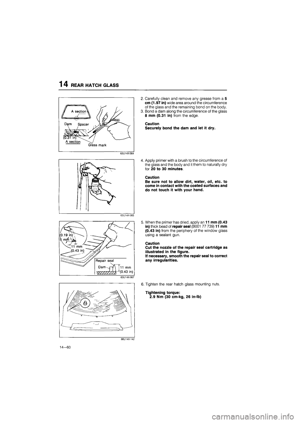
2. Carefully clean and remove any grease from a 5
cm (1.97 in) wide area around the circumference
of the glass and the remaining bond on the body.
3. Bond a dam along the circumference of the glass
8 mm (0.31 in) from the edge.
Caution
Securely bond the dam and let it dry.
63U14X-064
4. Apply primer with a brush to the circumference of
the glass and the body and
it
them to naturally dry
for 20 to 30 minutes.
Caution
Be sure not to allow dirt, water, oil, etc. to
come in contact with the coated surfaces and
do not touch it with your hand.
63U14X-065
5. When the primer has dried, apply an 11 mm (0.43
in) thick bead of repair seal (B001 77 739) 11 mm
(0.43 in) from the periphery of the window glass
using a sealant gun.
Caution
Cut the nozzle of the repair seal cartridge as
illustrated in the figure.
If necessary, smooth the repair seal to correct
any irregularities.
63U14X-067
6. Tighten the rear hatch glass mounting nuts.
Tightening torque:
2.9 N-m (30 cm-kg, 26 in-lb)
86U14X-142
14—60
Page 1660 of 1865
INTRODUCTION 15
69G15X-006
4BG15X-003
69G15X-007
/Wire
Shield braid wire
Insulation
Replacement of Fuse
1. When replacing a fuse, be sure to replace it with
one of the specified capacity.
If, after a fuse has been replaced, it fails again, there
is probably a short in the circuit, and the wiring
should be checked.
2. Be sure the negative battery terminal is disconnect-
ed before replacing a main fuse.
3. When replacing a fuse, use the supplied fuse puller
in the fuse box cover.
Thin Insulation Wire
To reduce the weight of the wiring harness, a thin
coating of high resistance insulation material is used.
Shielded braid wire
This wire is used to prevent a malfunction in impor-
tant circuits that are susceptible to outside signals or
interference.
Eg.
Ignition coil
02 sensor
69G15X-008
15—5
Page 1661 of 1865
15 INTRODUCTION
ELECTRICAL SYMBOLS
Switches and Relays
There is an NC (normally closed) and NO (normally open) indication for switches and relays; this indi-
cates the condition when there has been no change of operating conditions.
Relay
NO type relay NC type relay
Switch
NO switch NC switch
Not
in
operation (No power supply)
—Jtfiifij —o o—
Flow Stop Flow
In operation (Power supply)
^
^aijuiy—'
Flow
l=3X
Stop
Flow
Stop
Other Electrical Symbols
Holder
Box —
© ©
Holder
Box —
Holder
Box —
BATTERY BODY GROUND FUSE FUSIBLE LINK
(£)
* 1 fc
MOTOR COIL, SOLENOID RESISTOR VARIABLE RESISTOR
1
ii
-L ©
THERMISTER DIODE CONDENSER LIGHT
1
TRANSISTOR SPEAKER CIGARETTE LIGHTER HEATER
69G15X-009
15—6
Page 1690 of 1865
WARNING LIGHT AND SENDER 1 5
Washer Fluid Low Level Warning Light
76G15X-039
76G15X-040
Engine Oil Pressure Warning Light
76G15X-041
15—35
Page 1695 of 1865
15 WARNING AND SENDER
86U15X-068
86U15X069
86U15X-070
Door Switch
1. Check for continuity of the switch with an
ohmmeter.
2. If continuity is not as specified, replace the switch.
Washer Level Sensor
1. Check for continuity between C (LY) terminal and
D (B) terminal of the washer level sensor con-
nector.
Oil Pressure Switch
1. Disconnect the connector from the oil pressure
switch.
2. Check for continuity between the switch and a
body ground with each condition.
Coolant Level Sensor
1. Remove the level sensor and connect the con-
nector.
2. With the sensor not grounded to the body, start
the engine.
3. After checking that the warning light illuminates,
ground the threaded part of the sensor.
4. If the warning light remains illuminated, the sen-
sor is faulty and replace it.
73G15X-013
15—40
Engine Continuity
Running Yes
Stop No
Terminals Float level Continuity
C (LY)—D
(B)
Bottom Yes C (LY)—D
(B)
Above bottom No
2. If continuity is not as specified, replace the sensor.
Page 1739 of 1865

1 5 CRUISE CONTROL SYSTEM
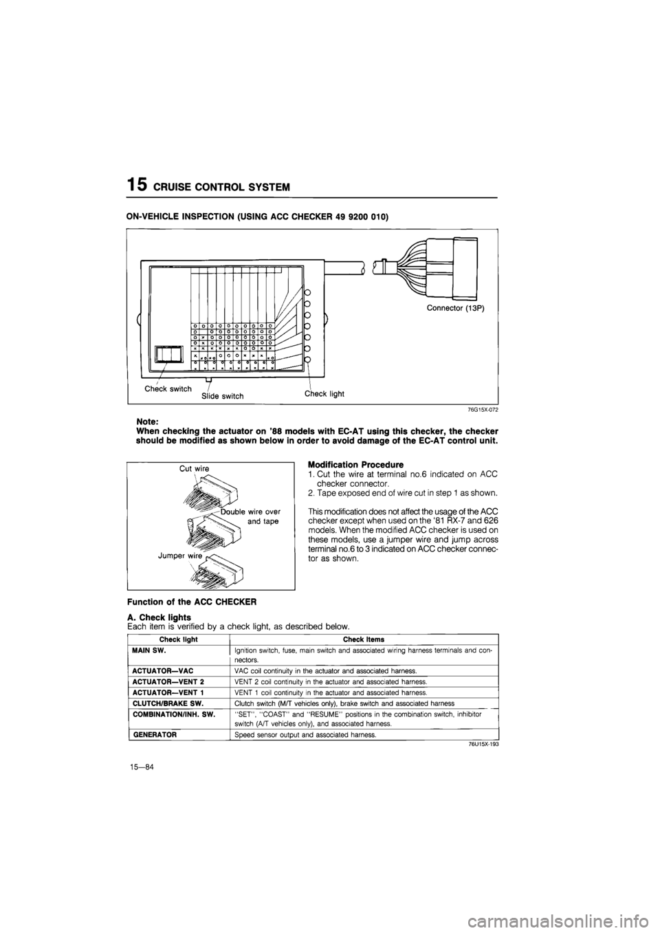
ON-VEHICLE INSPECTION (USING ACC CHECKER 49 9200 010)
76G15X-072
Note:
When checking the actuator on '88 models with EC-AT using this checker, the checker
should be modified as shown below in order to avoid damage of the EC-AT control unit.
Modification Procedure
1. Cut the wire at terminal no.6 indicated on ACC
checker connector.
2. Tape exposed end of wire cut in step 1 as shown.
This modification does not affect the usage of the ACC
checker except when used on the '81 RX-7 and 626
models. When the modified ACC checker is used on
these models, use a jumper wire and jump across
terminal no.6 to 3 indicated on ACC checker connec-
tor as shown.
Function of the ACC CHECKER
A. Check lights
Each item is verified by a check light, as described below.
Check light Check items
MAIN SW.
Ignition switch, fuse, main switch and associated wiring harness terminals and con-
nectors.
ACTUATOR—VAC
VAC coil continuity
in
the actuator and associated harness.
ACTUATOR—VENT 2
VENT
2
coil continuity
in
the actuator and associated harness.
ACTUATOR—VENT 1
VENT
1
coil continuity
in
the actuator and associated harness.
CLUTCH/BRAKE SW.
Clutch switch (M/T vehicles only), brake switch and associated harness
COMBINATION/INH. SW.
"SET", "COAST" and "RESUME" positions
in
the combination switch, inhibitor
switch (A/T vehicles only), and associated harness.
GENERATOR
Speed sensor output and associated harness.
76U15X-193
15-84
Page 1788 of 1865

OUTLINE 16
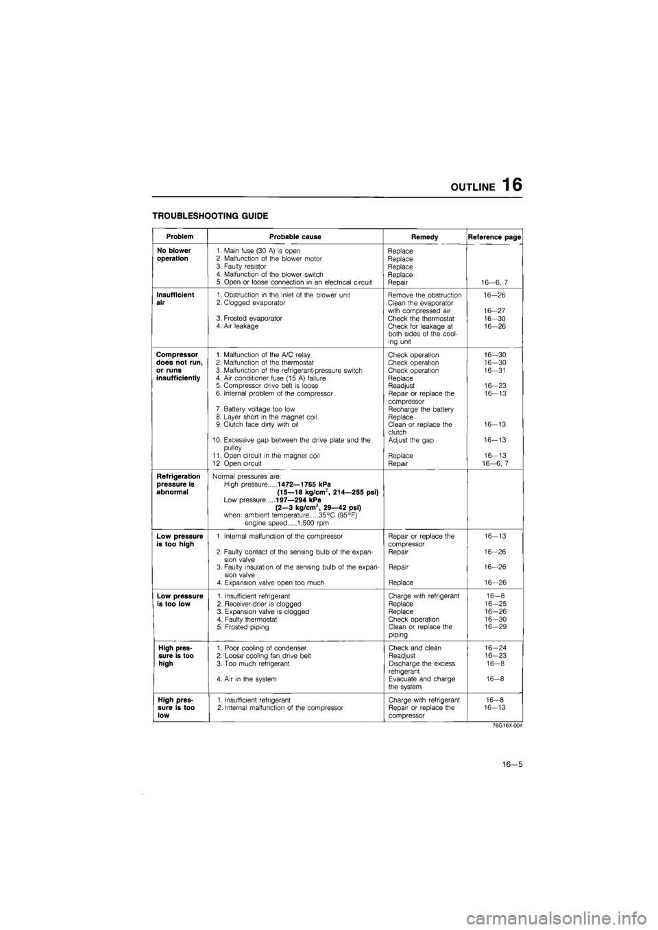
TROUBLESHOOTING GUIDE
Problem Probable cause Remedy Reference page
No blower
1. Main fuse (30
A) is
open Replace
operation
2 Malfunction
of
the blower motor Replace 3. Faulty resistor Replace 4. Malfunction
of
the blower switch Replace 5. Open
or
loose connection
in an
electrical circuit Repair 16—6,
7
Insufficient
1. Obstruction
in
the inlet
of
the blower unit Remove the obstruction 16-26
air
2. Clogged evaporator Clean the evaporator
with compressed
air
16-27 3. Frosted evaporator Check the thermostat 16-30 4. Air leakage Check for leakage
at
16-26 both sides
of
the cool-
ing unit
Compressor
1. Malfunction
of
the A/C relay Check operation 16—30
does not run,
2. Malfunction
of
the thermostat Check operation 16—30
or runs
3. Malfunction
of
the refrigerant-pressure switch Check operation 16—31
insufficiently
4.
Air
conditioner fuse (15
A)
failure Replace 5. Compressor drive belt
is
loose Readjust 16—23
6. Internal problem
of
the compressor Repair
or
replace
the
16—13
compressor 7. Battery voltage too low Recharge the battery 8. Layer short
in
the magnet coil Replace 9. Clutch face dirty with
oil
Clean
or
replace the 16-13
clutch 10. Excessive gap between the drive plate and
the
Adjust the gap 16-13
pulley
11. Open circuit
in
the magnet coil Replace 16—13
12 Open circuit Repair 16-6,
7
Refrigeration
Normal pressures are:
pressure is
High pressure
1472—1765 kPa
abnormal (15—18 kg/cm2, 214—255 psi)
Low pressure
197—294 kPa
(2—3 kg/cm2, 29—42 psi)
when: ambient temperature 35°C (95°F)
engine speed 1,500
rpm
Low pressure
1. Internal malfunction
of
the compressor Repair
or
replace the 16-13
is too high
compressor
2. Faulty contact
of
the sensing bulb
of
the expan-Repair 16-26
sion valve 3. Faulty insulation
of
the sensing bulb
of
the expan-Repair 16—26
sion valve
4. Expansion valve open too much Replace 16—26
Low pressure
1. Insufficient refrigerant Charge with refrigerant 16-8
is too low
2. Receiver-drier
is
clogged Replace 16-25
3. Expansion valve
is
clogged Replace 16-26
4. Faulty thermostat Check operation 16-30 5. Frosted piping Clean
or
replace the 16—29
piping
High pres-
1. Poor cooling
of
condenser Check and clean 16-24
sure is too
2. Loose cooling fan drive belt Readjust 16—23
high
3. Too much refrigerant Discharge the excess 16-8
refrigerant 4.
Air in
the system Evacuate and charge 16-8
the system
High pres-
1. Insufficient refrigerant Charge with refrigerant 16-8
sure is too
2. Internal malfunction
of
the compressor Repair
or
replace the 16-13
low
compressor
76G16X-004
16—5