Page 1336 of 1865
10 MANUAL STEERING
MANUAL STEERING
DISASSEMBLY
Disassemble in the sequence shown in the figure, referring to the disassembly note for specialy marked
parts.
Note
Before disassembling, drain the gear oil and remove all external grease and dirt.
86U10X088
1. Tie-rod end
2. Nut
3. Clip
4. Boot wire
5. Boot
6. Tie-rod
7. Washer
8. Adjust cover locknut
9. Adjust cover
10. Spring
11. Friction block
12. Dish spring
13. Holder
14. Needle roller
15. Roller assembly
16. Boot support
17. Rear cover locknut
18. Rear cover and oil seal
19. Bearing
20. Pinion
21. Bearing
22. Rack
23. Gear housing
24. Mounting rubber and
bracket
25. Bushing
10—48
Page 1341 of 1865
MANUAL STEERING 1 0
86U10X-103
86U10X-104
86U10X-105
1. Install the mounting rubber and bracket.
2. Install the bushing.
Align A with B and press the bushing into the gear
housing until it is fully seated.
3. Press in the lower bearing.
Caution
a) Before pressing in, put grease (lithium base,
NLGI No. 2) in the bearing and bearing bore.
b) Install the bearing in the proper direction. c) Use the pinion to press the bearing in.
4. Fill or coat the following points with grease (lithi-
um base, NLGI No. 2) before assembly.
a) Pinion bearing and teeth
b) Inside gear housing
c) Oil seal lip
d) Roller surface
e) Holder
f) Friction block surface
69G10X-106
10-53
Page 1342 of 1865
10 MANUAL STEERING
86U10X-107
86U10X-108
Pinion^ -1
Notch A Y
COSSSSW1
Rack
Central position
86U10X-109
g) Inner surface of housing rack bushing
h) Rack gear and outer circumference of rack shaft
L = 180 mm (7.09 in)
i) Tie-rod ball-joint
j) Inside left and right boots
Caution
Be careful not to fill the ventilation holes in
the rack shaft with grease.
5. Carefully install the rack in the direction of the
arrow.
6. Set the notch of the teeth of the rack at the pinion
position, then insert the pinion.
Caution
This notch is used for adjustment of the pin-
ion bearing preload without the pinion en-
gaged with the rack.
7. Install the upper bearing, and then screw on the
rear cover.
Caution
a) Apply sealant to the threads of the rear
cover.
b)Do not install the oil seal.
c) Screw on the rear cover with the SST.
86U10X-110
10—54
Page 1344 of 1865

10 MANUAL STEERING
86U10X-115
86U10X-116
86U10X-117
Dust Cover
)
2
Oil seal
is Nm
sn n
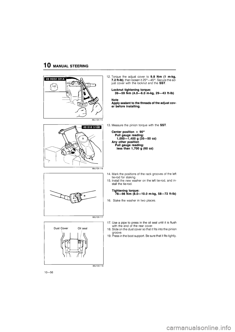
12. Torque the adjust cover to 9.8 N-m (1 m-kg,
7.2 ft-lb), then loosen it 25°—45°. Secure the ad-
just cover with the locknut and the SST.
Locknut tightening torque:
39—59 N-m (4.0—6.0 m-kg, 29—43 ft-lb)
Note
Apply sealant to the threads of the adjust cov-
er before installing.
13. Measure the pinion torque with the SST.
Center position ± 90°
Pull gauge reading:
1,000—1,400 g (35—50 oz)
Any other position
Pull gauge reading:
less than 1,700 g (60 oz)
14. Mark the positions of the rack grooves of the left
tie-rod for staking.
15. Install the new washer on the left tie-rod, and in-
stall the tie-rod.
Tightening torque:
78—98 N-m (8.0—10.0 m-kg, 58—72 ft-lb)
16. Stake the washer in two places.
17. Use a pipe to press in the oil seal until it is flush
with the end of the rear cover.
18. Slide on the dust cover so that it fits into the pinion
groove.
19. Press in the boot support. Be sure that it fits tightly.
86U10X-118
10—56
Page 1346 of 1865

1 0 ENGINE SPEED SENSING POWER STEERING
ENGINE SPEED SENSING POWER STEERING
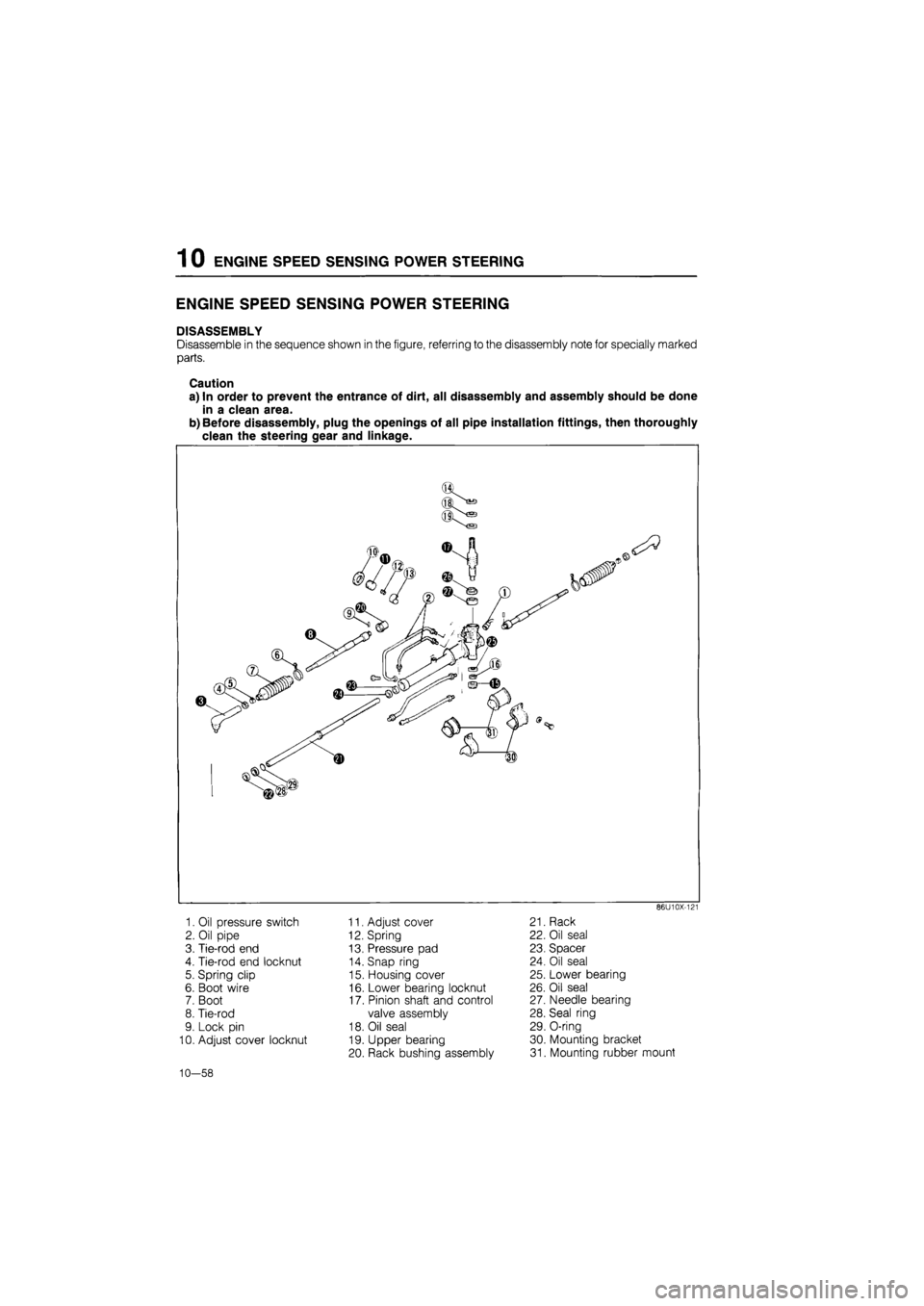
DISASSEMBLY
Disassemble in the sequence shown in the figure, referring to the disassembly note for specially marked
parts.
Caution
a) In order to prevent the entrance of dirt, all disassembly and assembly should be done
in a clean area.
b) Before disassembly, plug the openings of all pipe installation fittings, then thoroughly
clean the steering gear and linkage.
86U10X-121
1. Oil pressure switch
2. Oil pipe
3. Tie-rod end
4. Tie-rod end locknut
5. Spring clip
6. Boot wire
7. Boot
8. Tie-rod
9. Lock pin
10. Adjust cover locknut
11. Adjust cover
12. Spring
13. Pressure pad
14. Snap ring
15. Housing cover
16. Lower bearing locknut
17. Pinion shaft and control
valve assembly
18. Oil seal
19. Upper bearing
20. Rack bushing assembly
21. Rack
22. Oil seal
23. Spacer
24. Oil seal
25. Lower bearing
26. Oil seal
27. Needle bearing
28. Seal ring
29. O-ring
30. Mounting bracket
31. Mounting rubber mount
10—58
Page 1348 of 1865
1 0 ENGINE SPEED SENSING POWER STEERING
Housing cover
1. Cut away the staked areas with a drill.
2. Remove the housing cover.
86U10X-126
Pinion shaft
1. Remove the locknut.
2. Set the gear housing assembly on a press and re-
move the pinion shaft assembly as shown in the
figure.
86U10X-127
Rack bushing
1. Cut away the staked areas with a drill.
2. Remove the rack bushing.
86U10X-128
Rack and oil seal at tube side
1. Slide the SST over the rack from the gear hous-
ing side.
Note
If the rack is removed without using the SST,
there is the possibility that the rack housing
may be damaged by the rack teeth.
86U10X-129
10—60
Page 1349 of 1865
ENGINE SPEED SENSING POWER STEERING 1 0
86U10X-130
86U10X-131
86U10X-132
2. Install the SST to the threaded part of the rack at
the tube side.
3. Remove the oil seal at the tube side which pulling
out the rack.
Spacer and oil seal at housing side
1. Insert the SST from the pinion housing side so that
it contacts the spacer.
2. Set the SST against the SST inserted in step 1.
3. Secure the gear housing in a vise.
4. Drive the spacer and oil seal out of the housing.
Lower bearing
Drive the lower bearing out of the housing with the
SST
86U10X-133
10-61
Page 1350 of 1865
1 0 ENGINE SPEED SENSING POWER STEERING
Oil seal and needle bearing
1. Insert the SST so that it contacts the needle
bearing.
2. Drive the oil seal and needle bearing out with the
SST bar.
86U10X-134
^aFm / y^s.
INSPECTION
Check the following and replace any faulty parts.
Pinion shaft assembly
1. Pinion shaft teeth wear or damage
2. Control valve damage, clogging, and wear
86U10X-135
Rack bushing
Wear or damage
86U10X-136
Bearing
Wear, damage, and operation
86U10X-137
10—62