Page 1272 of 1865
REAR AXLE 9
DISASSEMBLY
Disassemble in the sequence shown in the figure referring to the disassembly note for the specially
marked parts.
1. Oil seal
2. Sensor rotor (ABS)
3. Retaining ring
4. Rear wheel bearing
5. Disc plate
86U09X-042
S 49 0839 425C
49 F027 007
86U09X-087
Disassembly Note
Note
a) Do not remove the hub bolts unless
necessary.
b)Do not reuse the hub bolts if removed.
Sensor rotor (ABS)
Remove the sensor rotor with the SST.
Note
a) Do not remove the sensor rotor unless
necessary.
b)Do not reuse the sensor rotor if removed.
Rear wheel bearing
Remove the rear wheel bearing with the SST.
Note
Do not reuse the rear wheel bearing if
removed.
86U09X-085
9-23
Page 1273 of 1865
INSPECTION
Check as described below, replace parts if necessary.
1. Check the hub for cracks or damage.
69G09X-028
2. Check the sensor rotor for cracks or damage.
69G09X-029
3. Check the knuckle spindle for cracks or damage,
and the oil seal friction surface for wear or rust.
86U09X-043
4. Check the dust cover for damage.
5. Check the hub cap for damage.
69G09X-031
Page 1274 of 1865
REAR AXLE 9
ASSEMBLY
1. Install new hub bolts.
86U09X-045
2. Install a new sensor rotor with the SST. (ABS)
86U09X-046
3. Install a new rear wheel bearing with the SST.
4. Install the retaining ring.
86U09X-047
5. Install a new oil seal with the SST.
Note
Apply grease to the oil seal lip.
86U09X-048
9—25
Page 1279 of 1865
9 DRIVESHAFT
86U09X-055
86U09X-056
Driveshaft
Disconnect the driveshaft from the transaxle with a
prybar.
Note
Do not damage the boot or the oil seal.
Joint shaft
As shown in the figure, insert a pry bar between the
driveshaft and the joint shaft and tap on the bar to
uncouple them.
Front wheel hub
Use the SST to push the shaft out if it is stuck in the
front wheel hub.
86U09X-057
Differential
Install the SST to hold the side gear after removing
the driveshaft.
86U09X-058
9—30
Page 1286 of 1865
DRIVESHAFT 9
INSTALLATION
Install in the reverse order of removal referring to the installation note.
Torque specifications
42—62 N m (4.3—6.3 m-kg, 31—46 ft-lb)
8—11 N-m (80—110 cm-kg,
7—10 N-m (70—100 cm-kg, 60—86 in-lb)
16—23 N-m
(1.6—2.3 m-kg, 12—17 ft-lb)
29—44 N-m (3.0—4.5 m-kg, 22—33 ft-lb)
43—54 N-m (4.4—5.5 m-kg, 32—40 ft-lb)
8—11 N-m (80—110 cm-kg, 69—95 In-lb)
235—319 N-m (24.0—32.5 m-kg, 174—235 ft-lb)
88—118 N-m (9.0—12.0 m-kg 65—87 ft-lb)
86U09X-070
I Apply grease
^^TBT0J
if
Clip
Installation Note
Clip
Install a new clip.
Note
a) Before installing the shaft, check the trans-
axle oil seal for damage.
b) Apply transaxle oil to the oil seal lip.
86U09X-071
9-37
Page 1288 of 1865
DRIVESHAFT 9
JOINT SHAFT
Disassembly and Assembly
Disassemble in the sequence shown in the figure.
Assembly in the reverse order of disassembly.
Referring to the notes for the specially marked parts.
1. Clip
2. Joint shaft
3. Oil seal
4. Oil seal
5. Bearing
6. Bracket
76G09X-005
Disassembly Note
Bearing
Remove the shaft and bearing with the SST and
press.
Caution
Hold the shaft and the bearing by hand does
not drop.
86U09X-076
Assembly Note
Bearing
1. Install the shaft and a new bearing with.the SST
and press.
2. Install new oil seals.
3. Install a new clip.
86U09X-077
9-39
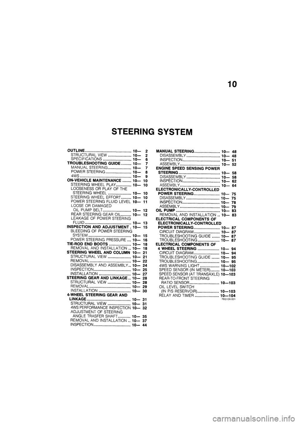
Page 1289 of 1865

10
STEERING SYSTEM
OUTLINE 10— 2
STRUCTURAL VIEW 10— 2 SPECIFICATIONS 10— 6
TROUBLESHOOTING GUIDE 10— 7
MANUAL STEERING 10— 7
POWER STEERING 10— 8
4WS 10— 9
ON-VEHICLE MAINTENANCE 10— 10
STEERING WHEEL PLAY 10— 10
LOOSENESS OR PLAY OF THE
STEERING WHEEL 10— 10
STEERING WHEEL EFFORT 10— 10
POWER STEERING FLUID LEVEL 1 fl-11
LOOSE OR DAMAGED
OIL PUMP BELT IC— 12
REAR STEERING GEAR OIL 10— 12 LEAKAGE OF POWER STEERING
FLUID 10— 13
INSPECTION AND ADJUSTMENT. 10— 15
BLEEDING OF POWER STEERING
SYSTEM 10— 15
POWER STEERING PRESSURE ... 10— 16
TIE-ROD END BOOTS 10— 18
REMOVAL AND INSTALLATION .. 10— 18
STEERING WHEEL AND COLUMN 10— 21
STRUCTURAL VIEW 10— 21
REMOVAL 10— 22
DISASSEMBLY AND ASSEMBLY.. 10— 24
INSPECTION 10— 25
INSTALLATION 1 fl-27
STEERING GEAR AND LINKAGE .. IC— 28
STRUCTURAL VIEW 10— 28
REMOVAL 10— 29
INSTALLATION 10— 30
4-WHEEL STEERING GEAR AND
LINKAGE 10— 31
STRUCTURAL VIEW 10— 31 4WS PERFORMANCE INSPECTION 10— 32
ADJUSTMENT OF STEERING
ANGLE TRASFER SHAFT 10— 35
REMOVAL AND INSTALLATION .. 10— 37
INSPECTION 10— 44
MANUAL STEERING 10— 48
DISASSEMBLY 10— 48
INSPECTION 10— 51
ASSEMBLY 10— 52
ENGINE SPEED SENSING POWER
STEERING 10— 58
DISASSEMBLY 10— 58
INSPECTION 10— 62
ASSEMBLY 10— 64
ELECTRONICALLY-CONTROLLED
POWER STEERING 10— 75
DISASSEMBLY 10— 75
INSPECTION 10— 78
ASSEMBLY 10— 79
OIL PUMP 10— 83
REMOVAL AND INSTALLATION .. 10— 83
ELECTRICAL COMPONENTS OF
ELECTRONICALLY-CONTROLLED
POWER STEERING 10— 87
CIRCUIT DIAGRAM 10— 87
TROUBLESHOOTING GUIDE 10— 87
TROUBLESHOOTING 10— 87
ELECTRICAL COMPONENTS OF
4 WHEEL STEERING 10— 94
CIRCUIT DIAGRAM 10— 94
TROUBLESHOOTING GUIDE 10— 95
TROUBLESHOOTING 10— 95
4WS WARNING LIGHT 10—102
SPEED SENSOR (IN METER) 10—103
SPEED SENSOR (AT TRANSAXLE) 10—103
REAR-TO-FRONT STEERING
RATIO SENSOR 10—103
OIL LEVEL SWITCH
(IN P/S RESERVOIR) 10—103
RELAY AND TIMER 10—104 76G10X-001
Page 1291 of 1865
OUTLINE 10
1. Steering wheel
2. Steering shaft
3. Intermediate shaft
4. Steering gear assembly
5. Pressure hose
6. Return hose
7. Oil pump
8. Reserve tank
86U10X-003
Note
Engine speed sensing power steering is abbreviated ESPS.
10—3