Page 1316 of 1865
1 0 STEERING GEAR AND LINKAGE
STEERING GEAR AND LINKAGE
STRUCTURAL VIEW
Manual steering
Power steering
1. Oil pressure switch connector
2. Pipes
3. Tie-rod end
4. Steering shaft universal joint
5. Mud flap
86U10X-051
10-28
Page 1319 of 1865
4-WHEEL STEERING GEAR AND LINKAGE 1 0
4-WHEEL STEERING GEAR AND LINKAGE
STRUCTURAL VIEW
1. Reserve tank
2. Oil pump
3. Front steering gear assembly
4. Speed sensor
5. Control unit
6. Steering angle transfer shaft
7. Solenoid valve
8. Rear steering gear assembly
9. Steering wheel
10. Steering shaft
11. Relay and timer
86U10X-056
10—31
Page 1329 of 1865
4-WHEEL STEERING GEAR AND LINKAGE 1 0
2. Remove the cover and the brake pipe joint block.
86U10X-071
3. Remove the mounting bolts and nuts from the left
and right subframes.
4. Let the subframes hang down.
86U10X-072
J i/W i
Y
Solenoid valves
1. Remove the oil pipes.
2. Remove the bolts.
3. Disconnect the solenoid valve connectors.
4. Remove the solenoid valve assembly.
86U10X-073
Oil filter
Replace the oil filter in the sequence shown in the
figure.
1. Filter cap 5. Rubber
2. O-ring 6. Oil filter
3. Spring 7. Magnet
4. Set plate
Note
Clean up and install the magnet and set plate.
86U10X-074
10—41
Page 1330 of 1865

1 0 4-WHEEL STEERING GEAR AND LINKAGE
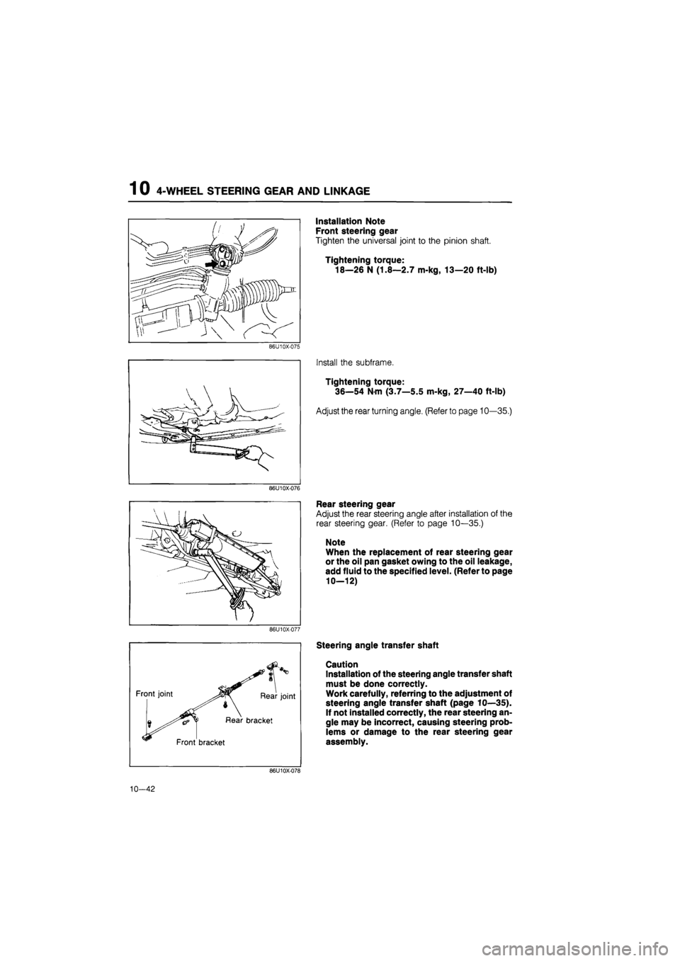
86U10X-075
86U10X-076
86U10X-077
Front joint Rear joint
Rear bracket
Front bracket
Installation Note
Front steering gear
Tighten the universal joint to the pinion shaft.
Tightening torque:
18—26 N (1.8—2.7 m-kg, 13—20 ft-lb)
Install the subframe.
Tightening torque:
36—54 Nm (3.7—5.5 m-kg, 27—40 ft-lb)
Adjust the rear turning angle. (Refer to page 10—35.)
Rear steering gear
Adjust the rear steering angle after installation of the
rear steering gear. (Refer to page 10—35.)
Note
When the replacement of rear steering gear
or the oil pan gasket owing to the oil leakage,
add fluid to the specified level. (Refer to page
10—12)
Steering angle transfer shaft
Caution
Installation of the steering angle transfer shaft
must be done correctly.
Work carefully, referring to the adjustment of
steering angle transfer shaft (page 10—35).
If not installed correctly, the rear steering an-
gle may be incorrect, causing steering prob-
lems or damage to the rear steering gear
assembly.
86U10X-078
10—42
Page 1331 of 1865
4-WHEEL STEERING GEAR AND LINKAGE 1 0
76G10X-035
1. Temporarily install the front bracket.
2. Install the rear bracket, and then tighten at the
specified torque.
Tightening torque:
22—30 Nm (2.2—3.1 m-kg, 5.1—7.2 ft-lb)
3. Tighten the front bracket bolt.
Tightening torque:
22—30 Nm (2.2—3.1 m-kg, 5.1—7.2 ft-lb)
Caution
The shaft should be installed by two or more
persons, taking care not to bend the joint part.
4. Connect the joint of the front steering gear side,
and then tighten the bolt.
5. Connect the joint of the rear steering gear side, and
then tighten the bolt.
86U10X-320
Caution
Check to be sure that the front and rear brack-
ets do not contact the oil seal.
86U10X-321
Attach a new wire and clamp, and as shown in the
illustration be sure that protrusion is within 5mm
(0.2 in).
Install the cover.
86U10X-322
10—43
Page 1332 of 1865
1 0 4-WHEEL STEERING GEAR AND LINKAGE
INSPECTION
Front Steering Gear and Linkage
1. Check the following and replace the front steering
gear assembly if necessary.
(a) Damaged or cracked case
(b) Bent linkage
86U10X-079
2. Check the following and replace any faulty parts.
(a) Clogged, bent, or pinched pipes
(b) Faulty oil pressure switch
(c) Damaged mounting bracket and mounting
rubber
(d) Cracked, damaged, or deteriorated boots
86U10X-080
Available spare parts
86U10X-081
1. Tie-rod end 7. Oil pressure switch
2. Tie-rod end boot 8. O-ring
3. Nut 9. Mounting bracket
4. Boot 10. Mounting rubber
5. Boot band (large) 11. Oil pipe
6. Boot band (small) 12. Steering gear assembly
10—44
Page 1334 of 1865
1 0 4-WHEEL STEERING GEAR AND LINKAGE
86U10X-085
Rear Steering Gear and Linkage
1. Check the following and replace the rear steering
gear assembly if necessary.
(a) Damaged or cracked case
(b) Faulty stepper motor or rear-to-front steering
ratio sensor
(c) Sticking bearings
(d) Oil leakage
Note
There is no fluid in a new replacement rear
steering gear assembly, add fluid to the spe-
cified level. (Refer to 10—12.)
2. Check and tighten bolts and nuts, if necessary.
3. Check the following and replace any faulty parts.
(a) Cracked, damaged, or deteriorated rear stee-
ring gear boots and bands
(b) Cracked or damaged oil pan
(c) Malfunctioning solenoid valve
86U10X-086
10-46
Page 1335 of 1865
4-WHEEL STEERING GEAR AND LINKAGE 1 0
Available spare parts
86U10X-087
1. Tie-rod end 9.
2. Tie-rod end boot 10.
3. Nut 11.
4. Boot 12.
5. Boot band (wire) 13.
6. Boot band (clip) 14.
7. Oil pan 15.
8. Oil pan gasket 16.
Bolt
Oil filler bolt
Solenoid valve (Refer to 10—41)
Bolt
Oil filter set (Refer to 10—41)
Steering gear assembly
Pipe
10—47