Page 1957 of 2389
10. INSERT NO. 1 CLUTCH HUB INTO HUB SLEEVE
(a) Install the clutch hub and shifting keys to the hub
sleeve.
(b) Install the shifting key springs under the shifting keys.
NOTICE: Install the key springs positioned so that their end
gaps are not in line.
9. IF OUTPUT SHAFT WAS REPLACED, DRIVE IN
SLOTTED SPRING PIN
If the output shaft was replaced, drive the slotted spring
pin in the output shaft to a depth of 5.0 mm (0.197 in.).
11. INSTALL THRUST WASHER, FIRST GEAR, NEEDLE
ROLLER BEARING, SYNCHRONIZER RING AND
NO. 1 HUB SLEEVE ASSEMBLY TO OUTPUT SHAFT
(a) Apply ATF to the needle roller bearing.
(b) Place the synchronizer ring on the gear and align the
ring slots with the shifting keys.
12. INSTALL SNAP RING
Select a snap ring that will allow minimum axial play
and install it on the shaft.(e) Using a press, install the 1 st gear and No. 1 hub sleeve.
Thickness
mm (in.)
Mark
± MANUAL TRANSAXLES51TransmissionMT±26
Page 1958 of 2389
14. INSTALL SPACER, SYNCHRONIZER RING, SECOND
GEAR, NEEDLE ROLLER BEARING AND THIRD
DRIVEN GEAR
(a) Install the spacer.
!by Place the synchronizer ring on the gear and align
the ring slots with the shifting keys.
(c) Apply ATF to the needle roller bearing.
(d) Install the 2nd gear. 13. MEASURE FIRST GEAR THRUST CLEARANCE
Using a feeler gauge, measure the 1 st gear thrust
clearance.
Standard clearance: 0.10 ± 0.29 mm
(0.0039 ± 0.0114 in.)
16. INSTALL OUTPUT GEAR SPACER, FOURTH DRIVEN
GEAR AND RADIAL BALL BEARING
(a) Install the spacer.
(b) Using SST, press in the 4th driven gear and bearing.
SST 09608±12010 (09608±00070) 15. MEASURE SECOND GEAR THRUST CLEARANCE
Using a feeler gauge, measure the 2nd gear thrust
clearance.
Standard clearance: 0.20 ± 0.44 mm (0.0079 ± 0.0173 in.) (e) Using a press, install the 3rd driven gear.
± MANUAL TRANSAXLES51 TransmissionMT±27
Page 1959 of 2389

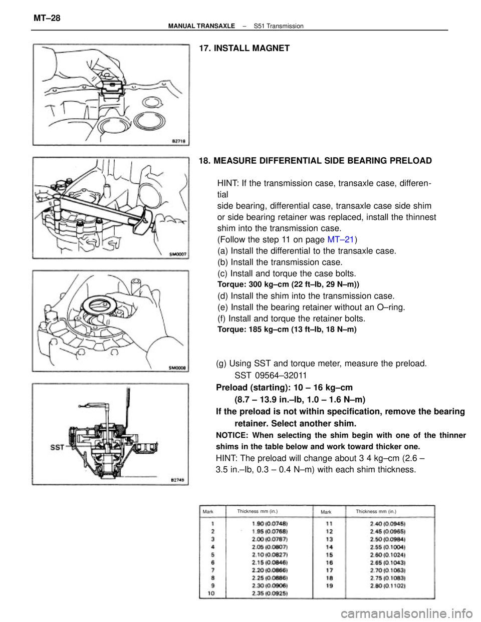
18. MEASURE DIFFERENTIAL SIDE BEARING PRELOAD
HINT: If the transmission case, transaxle case, differen-
tial
side bearing, differential case, transaxle case side shim
or side bearing retainer was replaced, install the thinnest
shim into the transmission case.
(Follow the step 11 on page MT±21)
(a) Install the differential to the transaxle case.
(b) Install the transmission case.
(c) Install and torque the case bolts.
Torque: 300 kg±cm (22 ft±Ib, 29 N±m))
(d) Install the shim into the transmission case.
(e) Install the bearing retainer without an O±ring.
(f) Install and torque the retainer bolts.
Torque: 185 kg±cm (13 ft±Ib, 18 N±m)
(g) Using SST and torque meter, measure the preload.
SST 09564±32011
Preload (starting): 10 ± 16 kg±cm
(8.7 ± 13.9 in.±Ib, 1.0 ± 1.6 N±m)
If the preload is not within specification, remove the bearing
retainer. Select another shim.
NOTICE: When selecting the shim begin with one of the thinner
shims in the table below and work toward thicker one.
HINT: The preload will change about 3 4 kg±cm (2.6 ±
3.5 in.±Ib, 0.3 ± 0.4 N±m) with each shim thickness. 17. INSTALL MAGNET
Thickness mm (in.)
Thickness mm (in.)
Mark
Mark
± MANUAL TRANSAXLES51 TransmissionMT±28
Page 1960 of 2389
21. INSTALL NO. 2 FORK SHAFT
(a) Insert No. 2 fork shaft to the transaxle case and align the
slotted spring pin hole.
(b) Using a pin punch and hammer, drive in the slotted spring
pin.
(c) Apply sealant to the plug threads.
Sealant: Part No. 08833±00080, THREE BOND 1344,
LOCTITE 242 or equivalent 19. REMOVE BEARING RETAINER, SHIM AND
TRANSMISSION CASE
If the preload is adjusted within specification, remove the
bearing retainer, shim and transmission case.
Be careful not to lose the adjusted shim.
22. INSTALL REVERSE SHIFT FORK AND INTERLOCK
PIN
(a) Insert interlock pin into the reverse shift fork hole.(d) Using SST, install the straight screw
plug.
SST 09313±30021
Torque: 130 kg±cm (9 ft±Ib, 13 N±m)
20. INSTALL INPUT AND OUTPUT SHAFTS
Install the input shaft and output shaft together.
± MANUAL TRANSAXLES51 TransmissionMT±29
Page 1961 of 2389
23. INSTALL REVERSE SHIFT ARM
(a) Put the reverse shift arm pivot into the reverse shift
fork and install the reverse shift arm to the transaxle case.
(b) Shift the reverse shift arm into reverse.
25. INSTALL NO. 1 AND NO. 2 SHIFT FORKS, NO. 1
SHIFT HEAD AND NO. 1 FORK SHAFT
(a) Place No. 1 and No. 2 shift forks into the groove of
No. 1 and No. 2 hub sleeves. (e) Install and torque the bolts.
Torque: 185 kg±cm (13 ft±lb, 18 N±m)
(d) Shift the reverse shift arm to neutral position.
24. INSTALL REVERSE IDLER GEAR AND SHAFT
Install the reverse idler gear and shaft as shown. (b) Install the reverse shift fork onto No. 2 fork shaft.
± MANUAL TRANSAXLES51 TransmissionMT±30
Page 1962 of 2389
27. INSTALL SHIM AND SIDE BEARING RETAINER
WITH O±RING
(a) Install a new 4±ring on the retainer.
(b) Install the shim and retainer.
(c) Apply sealant to the bolt threads.
Sealant: Part No. 08833±00080, THREE BOND 1344,
LOCTITE 242 or equivalent 26. INSTALL TRANSMISSION CASE
(a) Apply seal packing to the transmission case as shown in the
figure.
Seal packing: Part No. O8826±00090, THREE BOND
1281 or equivalent
(b) Install and torque the seventeen bolts.
Torque: 300 kg±cm (22 ft±tb, 29 N±m)
(d) Shift the fork shaft into reverse.
(e) Using a pin punch and hammer, drive the slotted
spring pin into No. 1 fork shaft. (b) Hold No. 1 shift head and insert No. 1 fork shaft
into the transaxle case through No. 1 and No. 2
shift forks, No. 1 shift head and reverse shift fork.
(e) Using a pin punch and hammer, drive the slotted
spring pin into No. 1 shift head.
± MANUAL TRANSAXLES51 TransmissionMT±31
Page 1963 of 2389
30. INSTALL REAR BEARING RETAINER
(a) Apply sealant to the bolt threads.
Sealant: Part No. 08833±00070, THREE BOND
1324, or equivalent
(b) Install and torque the five bolts.
Torque: 210 kg±cm (15 ft±Ib, 21 N± m)
28. INSTALL AND TORQUE REVERSE IDLER GEAR
SHAFT LOCK BOLT
Torque: 300 kg±cm (22 ft±Ib, 29 N±m)
31. INSTALL FIFTH DRIVEN GEAR
Using SST, install the 5th driven gear.
SST 09309±32050(d) Install and torque the six bolts.
Torque: 185 kg±cm (13 ft±lb, 18 N ±m)
29. INSTALL BEARING SNAP RINGS
± MANUAL TRANSAXLES51 TransmissionMT±32
Page 1964 of 2389

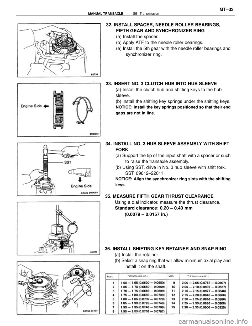
34. INSTALL NO. 3 HUB SLEEVE ASSEMBLY WITH SHIFT
FORK
(a) Support the tip of the input shaft with a spacer or such
to raise the transaxle assembly.
(b) Using SST, drive in No. 3 hub sleeve with shift fork.
SST 09612±22011
NOTICE: Align the synchronizer ring slots with the shifting
keys.
33. INSERT NO. 3 CLUTCH HUB INTO HUB SLEEVE
(a) Install the clutch hub and shifting keys to the hub
sleeve.
(b) install the shifting key springs under the shifting keys.
NOTICE: Install the key springs positioned so that their end
gaps are not in line.
32. INSTALL SPACER, NEEDLE ROLLER BEARINGS,
FIFTH GEAR AND SYNCHRONIZER RING
(a) Install the spacer.
(b) Apply ATF to the needle roller bearings.
(e) Install the 5th gear with the needle roller bearings and
synchronizer ring.
35. MEASURE FIFTH GEAR THRUST CLEARANCE
Using a dial indicator, measure the thrust clearance.
Standard clearance: 0.20 ± 0.40 mm
(0.0079 ± 0.0157 in.)
36. INSTALL SHIFTING KEY RETAINER AND SNAP RING
(a) Install the retainer.
(b) Select a snap ring that will allow minimum axial play and
install it on the shaft.
Thickness mm (in.) Thickness mm (in.) Mark
Mark
± MANUAL TRANSAXLES51 TransmissionMT±33