Page 2038 of 2389

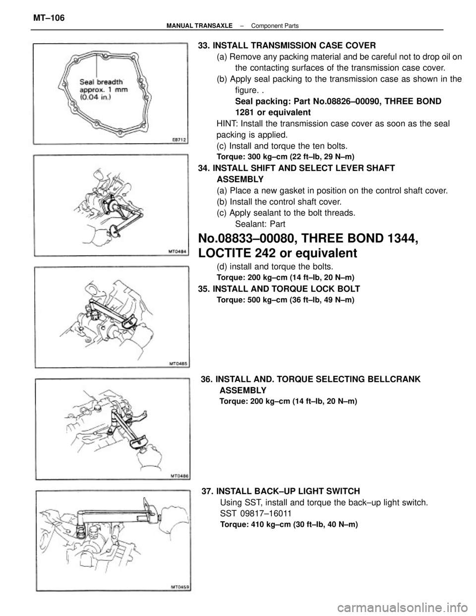
33. INSTALL TRANSMISSION CASE COVER
(a) Remove any packing material and be careful not to drop oil on
the contacting surfaces of the transmission case cover.
(b) Apply seal packing to the transmission case as shown in the
figure. .
Seal packing: Part No.08826±00090, THREE BOND
1281 or equivalent
HINT: Install the transmission case cover as soon as the seal
packing is applied.
(c) Install and torque the ten bolts.
Torque: 300 kg±cm (22 ft±Ib, 29 N±m)
34. INSTALL SHIFT AND SELECT LEVER SHAFT
ASSEMBLY
(a) Place a new gasket in position on the control shaft cover.
(b) Install the control shaft cover.
(c) Apply sealant to the bolt threads.
Sealant: Part
No.08833±00080, THREE BOND 1344,
LOCTITE 242 or equivalent
(d) install and torque the bolts.
Torque: 200 kg±cm (14 ft±Ib, 20 N±m)
35. INSTALL AND TORQUE LOCK BOLT
Torque: 500 kg±cm (36 ft±Ib, 49 N±m)
37. INSTALL BACK±UP LIGHT SWITCH
Using SST, install and torque the back±up light switch.
SST 09817±16011
Torque: 410 kg±cm (30 ft±Ib, 40 N±m)
36. INSTALL AND. TORQUE SELECTING BELLCRANK
ASSEMBLY
Torque: 200 kg±cm (14 ft±Ib, 20 N±m)
± MANUAL TRANSAXLEComponent PartsMT±106
Page 2040 of 2389

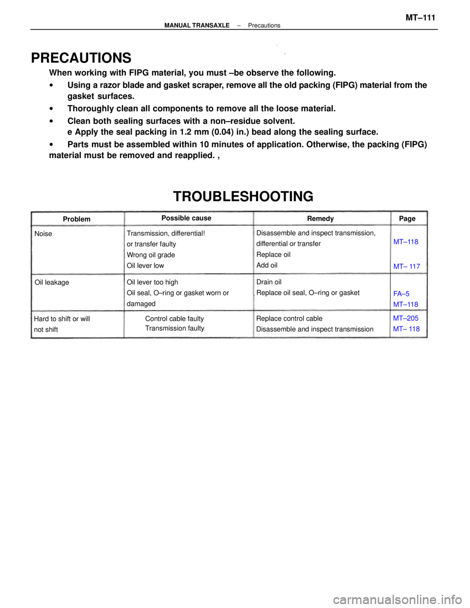
PRECAUTIONS
When working with FIPG material, you must ±be observe the following.
wUsing a razor blade and gasket scraper, remove all the old packing (FIPG) material from the
gasket surfaces.
wThoroughly clean all components to remove all the loose material.
wClean both sealing surfaces with a non±residue solvent.
e Apply the seal packing in 1.2 mm (0.04) in.) bead along the sealing surface.
wParts must be assembled within 10 minutes of application. Otherwise, the packing (FIPG)
material must be removed and reapplied. ,
Disassemble and inspect transmission,
differential or transfer
Replace oil
Add oil Transmission, differential!
or transfer faulty
Wrong oil grade
Oil lever low
Oil lever too high
Oil seal, O±ring or gasket worn or
damaged
Replace control cable
Disassemble and inspect transmissionDrain oil
Replace oil seal, O±ring or gasket
TROUBLESHOOTING
Control cable faulty
Transmission faulty Hard to shift or will
not shiftPossible cause
MT±205
MT± 118FA±5
MT±118 Oil leakageProblemRemedy
MT±118
MT± 117 NoisePage
± MANUAL TRANSAXLEPrecautionsMT±111
Page 2041 of 2389

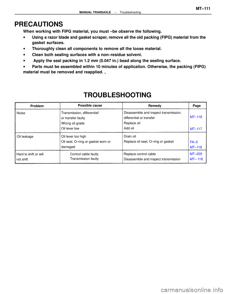
PRECAUTIONS
When working with FIPG material, you must ±be observe the following.
wUsing a razor blade and gasket scraper, remove all the old packing (FIPG) material from the
gasket surfaces.
wThoroughly clean all components to remove all the loose material.
wClean both sealing surfaces with a non±residue solvent.
w Apply the seal packing in 1.2 mm (0.047 in.) bead along the sealing surface.
wParts must be assembled within 10 minutes of application. Otherwise, the packing (FIPG)
material must be removed and reapplied. ,
Disassemble and inspect transmission,
differential or transfer
Replace oil
Add oil Transmission, differential!
or transfer faulty
Wrong oil grade
Oil lever low
Oil lever too high
Oil seal, O±ring or gasket worn or
damaged
Replace control cable
Disassemble and inspect transmissionDrain oil
Replace oil seal, O±ring or gasket
TROUBLESHOOTING
Control cable faulty
Transmission faulty Hard to shift or will
not shiftPossible cause
MT±205
MT± 118FA±5
MT±118 Oil leakageProblemRemedy
MT±118
MT±117 NoisePage
± MANUAL TRANSAXLETroubleshootingMT±111
Page 2047 of 2389
REPLACEMENT OF TRANSAXLE GEAR OIL
1. DRAIN TRANSAXLE OIL
2. FILL TRANSAXLE OIL WITH GEAR OIL
Oil: Transaxle oil E50 (08885±80206) or equivalent
Recommended oil
Oil grade: API G!±5
Viscosity: SAE 75W±90 or 80W±90
Above ±18°C (0°F) SAE 90
Below ±18°C (0°F) SAE 80W
Capacity: 5.0 liters (5.3 US qts, 4.4 Imp qts)
(MAIN POINT OF REMOVAL AND
INSTALLATION)
1. REMOVE TRANSAXLE ASSEMBLY
HINT: When removing transaxle from engine, remove as the
following procedure since cylinder block rib contacts
transfer case.
(a) Pull straight until there are space of 60 ± 80mm (2 ±3 in.)
between engine and transaxle case.
(e) While holding the transfer output slightly, pull out
whole transaxle.
2. INSTALL TRANSAXLE ASSEMBLY FOLLOWING
REMOVAL SEQUENCE IN REVERSE(b) Move the transmission case cover to the arrow in the
illustration.
± MANUAL TRANSAXLERemoval and Installation of TransaxleMT±117
Page 2063 of 2389
8. REMOVE SHIFT AND SELECT LEVER SHAFT ASSEMBLY
(a) Remove the four bolts and the shift and select lever
. shaft assembly.
(b) Remove the gasket from the shift and select lever shaft as-
sembly. 7. REMOVE SHIFT AND SELECT LEVER SHAFT LOCK
BOLT
(a) Remove the shift and select lever shaft lock bolt.
(b) Remove the gasket from the bolt.
9. REMOVE TRANSMISSION CASE COVER
(a) Remove the ten bolts.
(b) Using a plastic hammer, remove the case cover.
10. REMOVE OUTPUT SHAFT LOCK NUT
(a) Engage the gear double meshing.
(b) Using a chisel and hammer, unstake the lock nut.
± MANUAL TRANSAXLERemoval of Component PartsMT±122
Page 2067 of 2389
24. REMOVE TRANSMISSION CASE
Remove the seventeen bolts and tap off the case with a
plastic hammer.
wTransmission case side: Fourteen bolts
wTransaxle case side: Three bolts
21. REMOVE OUTPUT SHAFT REAR BEARING OUTER
RACE
Using a plastic hammer, remove the output shaft rear
bearing outer race.
23. REMOVE REVERSE SHIFT ARM BRACKET
Remove the bolt and pull off the bracket. 22. REMOVE NO.2 OIL PIPE
(a) Remove the gasket.
(b) Remove the two bolts and oil pipe.
± MANUAL TRANSAXLERemoval of Component PartsMT±126
Page 2080 of 2389
DISASSEMBLY OF SHIFT AND SELECT LEVER
SHAFT ASSEMBLY
1. REMOVE N0.2 SHIFT INNER LEVER
(a) Using a pin punch and a hammer, drive out the slatted spring pin
and remove the transmission oil baffle.
(b) Using two screwdrivers and a hammer, remove
the snap ring.
(c) Remove No.2 select spring seat, No.2 compres-
sor spring and No.2 shift inner lever.
Shift and Select Lever Shaft
± MANUAL TRANSAXLEComponent Parts (Shift and Select Lever ShaftMT±150
Page 2084 of 2389
6. INSTALL NO.2 SHIFT INNER LEVER
(a) Install the No.2 shift inner lever, No.2 compression
spring, transmission oil baffle and No.2 select spring
seat, as shown.
(c) Using a pin punch and hammer, drive in the
slotted spring pin. (b) Install the snap ring.
± MANUAL TRANSAXLEComponent Parts (Shift and Select Lever Shaft)MT±154