1986 TOYOTA CAMRY V20 battery
[x] Cancel search: batteryPage 765 of 2389

Turn Signal Flasher
INSPECTION OF FLASHER
INSPECT FLASHER OPERATION
(a) Connect the positive (+) lead from the battery to
terminal 3 and the negative (±) lead to terminal 2.
(b) Connect the two turn signal light bulbs parallel to each
other to terminals 1 and 2, check that the bulbs turn
on and off.
HINT: The turn signal lights should flash 60 to 120 times per
minute.
If one of the front or rear turn signal lights has an open cir±
cuit, the number of flashes will be more than 140 per mi
ute.
If operation is not as specified, replace the flashes. 2. INSPECT RELAY OPERATION
(a) Apply battery voltage to terminals 1 and 3.
(b) Check that there is continuity between terminals 2
and 4.
(c) Check that there is no continuity between terminals
3 and 4.
If operation is not as specified, replace the relay.
Hazard Warning Switch
INSPECTION OF SWITCH
INSPECT SWITCH CONTINUITY
Inspect the switch continuity between terminals.
If continuity is not as specified, replace the switch or
bulb.
Switch position
OFF (Free)
ON (Lock) Terminal0)c
o
N t
o(71
± BODY ELECTRICAL SYSTEMLightingBE±19
Page 766 of 2389

Taillight Failure Sensor
INSPECTION OF SENSOR
1. INSPECT WARNING LIGHT OPERATION
(a) Disconnect the connector from the failure sensor and
ground the terminal 3 on the wire harness side.
(b) Remove the CHARGE fuse and turn the ignition
switch ON, check that the bulb lights.
If bulb does not light, inspect the bulb.
2. INSPECT SENSOR CIRCUIT
Disconnect the failure sensor connector and inspect the
connector on the wire harness side as shown in the chart.
If circuit is as specified, replace the relay.
Stop light switch ON (Brake pedal depressed)Stop light switch OFF (Brake pedal released)
Turn light control switch TAIL or HEAD Turn ignition switch to OFF or ACC Turn ignition switch to OFF or ACC
Turn light control switch OFF Turn ignition switch ON
Remove CHARGE fuse
Turn ignition
switch ON
Install CHARGE fuse
Tester
connectionSpecified value
Battery voltage
Battery voltage
Battery voltageBattery voltage
No voltage Continuity
No voltageContinuityNo vottage No voltage Continuity
ContinuityNo voltage
Continuity ContinuityConditionCheck for
Voltage Voltage
VoltageAlways
AlwaysAlways
± BODY ELECTRICAL SYSTEMLightingBE±20
Page 767 of 2389

Integration Relay
INSPECTION OF RELAY
INSPECT RELAY CIRCUIT
Disconnect the relay connector and inspect the connector
on the wire harness side as shown in the chart.
Passenger's side and rear door courtesy switches OFF
(Door closed)
Passenger's side or rear door courtesy switch ON
(Door opened)
Turn headlight dimmer switch to low beam or high beamDriver's side door courtesy switch ON (Door opened)Driver's side door courtesy switch OFF (Door closed)
Turn light control switch to OFF or TAIL
Turn light control switch TAIL or HEADTurn headlight dimmer switch to FlashTurn ignition switch to OFF or ACC
Turn light control switch to HEAD
Turn light control switch OFF
(w/o Fade Out System)
Turn ignition switch ON
Tester
connectionSpecified value
Battery voltageBattery voltageBattery voltage Battery voltage
Battery voltageNo continuity
No continuityNo continuity Condition
No voltageContinuity
No voltageNo voltage
ContinuityContinuityContinuity
Continuity
Continuity Check for
VoltageVoltage
Voltage
AlwaysAlways
± BODY ELECTRICAL SYSTEMLightingBE±21
Page 768 of 2389

Room Light Retainer Switch
INSPECTION OF SWITCH
INSPECT SWITCH CONTINUITY
(a) Check that there is no continuity between terminals
with the switch OFF (Door outside handle released).
(b) Check that there is continuity between terminals with
the switch ON (Door outside handle pulled).
If continuity is not as specified, replace the switch.
Passenger's side and rear door courtesy switches OFF
(Door closed)
Passenger's side or rear door courtesy switch ON
(Door opened)Door room light retainer switch ON
(Door outside handle pulled up on driver's side)
Door room light retainer switch OFF
(Door outside handle released on driver's side)
Turn headlight dimmer switch to low beam or high beamDriver's side door courtesy switch ON (Door opened) Driver's side door courtesy switch OFF (Door closed)
If circuit is as specified, replace the relay.
Turn light control switch to OFF or TAIL
Turn light control switch TAIL or HEADTurn headlight dimmer switch to FlashTurn ignition switch to OFF or ACC
Turn light control switch to HEAD
Turn light control switch OFF
(w/ Fade Out System)
Condition
Turn ignition switch ON Tester
connectionSpecified value
Battery voltage
Battery voltageBattery voltage
Battery voltageBattery voltage
Battery voltageNo continuity
No continuity
No continuityNo continuity
No voltage
No voltageNo voltage
ContinuityContinuity
Continuity ContinuityContinuity
Continuity Continuity
ContinuityContinuity Always . Check for
Voltage
VoltageVoltage
Voltage
Always
AlwaysAlways
± BODY ELECTRICAL SYSTEMLightingBE±22
Page 769 of 2389

Current is led from the battery to terminal 12 of the running light relay.
Operation examples of the switch are shown below.
1. IGNITION SWITCH ºONº AND LIGHT CONTROL SWITCH ºOFFº
When the switches are set, current is led from the battery to terminal 1 of the running light relay. Also,
because continuity is made between terminal 3 and the body ground, and 5 and the body ground of
the running light relay, the taillight control relay and headlight control relay are turned on.
Then the taillights and headlights light up.
HINT: Because terminal 14 of the running light relay is not grounded at all times, the headlight dimmer
relay is off, so that the headlights light up at the low beam.
2. LIGHT CONTROL SWITCH IN ºHEADº
When the switch is set, continuity is made between terminal 4 and the body ground, and 2 and the body
ground of the running light relay. Also, because the continuity is made between terminal 5 and the body
ground, and 3 and the body ground of the running light relay at all times, the taillights and headlights
light up.
HINT: When the headlight dimmer switch is set to ºHIGHº, continuity is made between terminal 13 of
the running light relay and the body ground. Also, because continuity is made between terminal 14 of
the running light relay and the body ground, the headlight dimmer relay is turned on. Then the head-
lights go on at the high beam.
3. HEADLIGHT DIMMER SWITCH IN ºFLASHº
When the switch is set, continuity is made between terminal 6 and the body ground, and 13 and the
body ground of the running light relay. Also, because the continuity is made between terminal 5 and
the body ground, and 14 and the body ground of the running light relay, the headlights flash.
4. ENGINE STOPS (IGNITION SWITCH ºONº)
When the engine is stopped, because the continuity between terminal 5 and terminal 10 of the running
light relay remains, so the running lights also remain.
HINT: If ignition switch is turned to ºOFFº, running lights will go off because the continuity between termi-
nal 5 and terminal 10 of the running light relay is cut off.
Light Control Rheostat
INSPECTION OF RHEOSTAT
INSPECT RHEOSTAT OPERATION
(a) Connect the positive (+) lead from the battery to
terminal 1 and the negative (±) lead to terminal 2.
(b) Connect the terminals 1 and 3 through a 3.4 W test bulb.
(c) Gradually turn the rheostat knob from the bright side to
dark side, check that the test bulb brightness changes
from bright to dark.
If operation is not as specified, replace the rheostat.
Daytime Running Light System
(CANADA)
DESCRIPTION
± BODY ELECTRICAL SYSTEMLightingBE±23
Page 771 of 2389

(Relay Operation)
(a) Connect the positive (+) lead from the voltmeter to ter-
minal 7 and negative (±) lead to terminal 10.
(b) Check that there is battery voltage with light control
switch is turned on.
If operation is not as specified, replace the relay.If continuity is not as specified, replace the relay.
2. INSPECT DAYTIME RUNNING LIGHT RELAY
(Relay Circuit)
Disconnect the connector from the relay and inspect the
connector on the wire harness side as shown in the chart.
INSPECTION OF RELAY
1. INSPECT DIMMER RELAY (Continuity)
If circuit is as specified, inspect relay operation.
Apply battery voltage to
terminals 2 and 4.
Light control switch
position
Light control switch
position
Headlight dimmer
switch positionHeadlight dimmer
switch positionLow beam or High beam
Ignition switch
position 7 ± Ground
10 ± Ground
High beam or Flash 13 ± Ground
3 ± Ground
5 ± Ground
Tester connection
Ground terminal 5
Specified value
Battery voltageBattery voltageBattery voltage
Battery voltage Battery voltageNo continuity
No continuity TAIL or HEADNo continuity
No continuity
14 ± Ground12 ± GroundON or STARTLOCK or ACC
1 ± GroundOFF or TAIL
8 ± Ground2 ± Ground
6 ± Ground4 ± Ground
No voltage
No voltage
No voltageContinuity
Continuity Continuity
Continuity
ContinuityContinuity
Condition
Check for
Low beam Condition
Running
Terminal
Constant
Constant
Constant
Constant
Constant Voltage
EngineHEAD
Flash
StopOFF
± BODY ELECTRICAL SYSTEMLightingBE±25
Page 773 of 2389

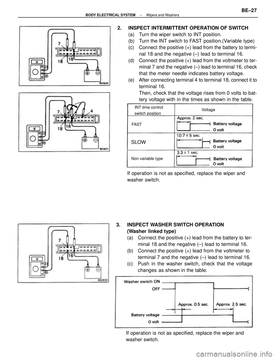
2. INSPECT INTERMITTENT OPERATION OF SWITCH
(a) Turn the wiper switch to INT position.
(b) Turn the INT switch to FAST position.(Variable type)
(c) Connect the positive (+) lead from the battery to termi-
nal 18 and the negative (±) lead to terminal 16.
(d) Connect the positive (+) lead from the voltmeter to ter-
minal 7 and the negative (±) lead to terminal 16, check
that the meter needle indicates battery voltage.
(e) After connecting terminal 4 to terminal 18, connect it to
terminal 16.
Then, check that the voltage rises from 0 volts to bat-
tery voltage with in the times as shown in the table.
3. INSPECT WASHER SWITCH OPERATION
(Washer linked type)
(a) Connect the positive (+) lead from the battery to ter-
minal 18 and the negative (±) lead to terminal 16.
(b) Connect the positive (+) lead from the voltmeter to
terminal 7 and the negative (±) lead to terminal 16.
(c) Push in the washer switch, check that the voltage
changes as shown in the table.
If operation is not as specified, replace the wiper and
washer switch.If operation is not as specified, replace the wiper and
washer switch.
INT time control
switch position
Non variable typeVoltage
SLOW
FAST
± BODY ELECTRICAL SYSTEMWipers and WashersBE±27
Page 774 of 2389

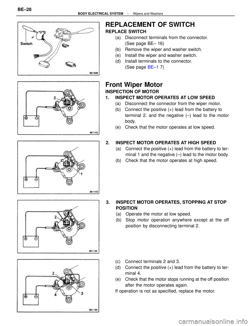
Front Wiper Motor
INSPECTION OF MOTOR
1. INSPECT MOTOR OPERATES AT LOW SPEED
(a) Disconnect the connector from the wiper motor.
(b) Connect the positive (+) lead from the battery to
terminal 2. and the negative (±) lead to the motor
body.
(e) Check that the motor operates at low speed.
REPLACEMENT OF SWITCH
REPLACE SWITCH
(a) Disconnect terminals from the connector.
(See page BE± 16)
(b) Remove the wiper and washer switch.
(e) Install the wiper and washer switch.
(d) Install terminals to the connector.
(See page BE±1 7)
(c) Connect terminals 2 and 3.
(d) Connect the positive (+) lead from the battery to ter-
minal 4.
(e) Check that the motor stops running at the off position
after the motor operates again.
If operation is not as specified, replace the motor. 3. INSPECT MOTOR OPERATES, STOPPING AT STOP
POSITION
(a) Operate the motor at low speed.
(b) Stop motor operation anywhere except at the off
position by disconnecting terminal 2. 2. INSPECT MOTOR OPERATES AT HIGH SPEED
(a) Connect the positive (+) lead from the battery to ter-
minal 1 and the negative (±) lead to the motor body.
(b) Check that the motor operates at high speed.
± BODY ELECTRICAL SYSTEMWipers and WashersBE±28