Page 638 of 2389

INSPECTION OF ELECTRIC CONTROL
COMPONENTS
1. INSPECT SHIFT LOCK CONTROL COMPUTER
Using a voltmeter, measure the voltage at each termi-
nals.
HINT: Do not disconnect the computer connector.
2. INSPECT SHIFT LOCK SOLENOID
(a) Disconnect the solenoid connector.
(b) Using an ohmmeter, measure the resistance be-
tween terminals.
Standard resistance: 21 ± 27
�
(c) Apply the battery voltage between terminals.
Check that an operation noise can be heard
from the solenoid.
Ignition switch 4N, P range and depress brake pedal Ignition switch ACC position and except P range
Shift except P range under conditions above
Shift except P range under condition above Ignition switch ACC position and P range
Ignition switch ACC position and P range Ignition switch ON position and P range Ignition switch ACC position
(Approx.±after 20 seconds) Ignition switch ON position
(Approx.±after one second) Depress brake pedalMeasuring condition
Depress brake pedal
Except P rangeVoltage (V)
ConnectorTerminal
± AUTOMATIC TRANSAXLEShift Lock SystemAT±410
Page 639 of 2389
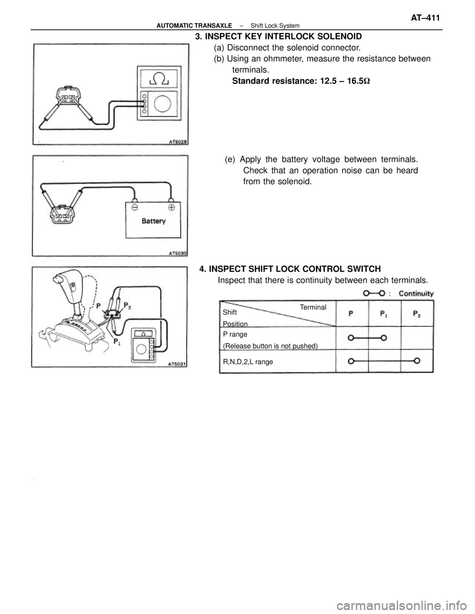
3. INSPECT KEY INTERLOCK SOLENOID
(a) Disconnect the solenoid connector.
(b) Using an ohmmeter, measure the resistance between
terminals.
Standard resistance: 12.5 ± 16.5�
(e) Apply the battery voltage between terminals.
Check that an operation noise can be heard
from the solenoid.
4. INSPECT SHIFT LOCK CONTROL SWITCH
Inspect that there is continuity between each terminals.
P range
(Release button is not pushed)
R,N,D,2,L range Shift
PositionTerminal
± AUTOMATIC TRANSAXLEShift Lock SystemAT±411
Page 722 of 2389
REMOVAL OF SUN ROOF
(See page BO±53)
1. DISCONNECT BATTERY CABLE FROM NEGATIVE
TERMINAL
2. REMOVE CONTROL SWITCH
3. REMOVE FOLLOWING PARTS:
wFront pillar garnishr Assist grip
wRear view mirror
wSun visor and holder
wOpening trim moulding
4. REMOVE CENTER PILLAR LOWER GARNISH
(a) Remove the front and rear door opening trims.
(b) Remove the front and rear scuff plates.
(e) Pry out the clips and remove the center pillar lower
garnish.
6. REMOVE FRONT SIDE ROOF HEADLINING
Tear off the roof headlining portion stuck with double±stick
tape between front all center pillar. 5. REMOVE CENTER PILLAR UPPER GARNISH
(a) (CANADA)
Remove the front shoulder belt anchor.
(b) Using a screwdriver, pry out the clips.
HINT: Tape the screwdriver tip before use.
(c) Remove the center pillar upper garnish.
± BODYSun RoofBO±56
Page 727 of 2389
(b) (CANADA)
Install the shoulder belt anchor with the bolt.
Torque: 440 kg±cm (32 ft±Ib, 43 N±m)
7. INSTALL CENTER PILLAR LOWER GARNISH
8. INSTALL SCUFF PLATE
9. INSTALL FOLLOWING PARTS:
wFront pillar garnish
wRear view mirror
wSun visor and holder
wAssist grip
wOpening trim moulding
10. INSTALL CONTROL SWITCH
11. INSPECT AND ADJUST SLIDING ROOF
(See pages BO±54 and 55)
12. CONNECT BATTERY CABLE TO NEGATIVE
TERMINAL
REMOVAL OF SLIDING ROOF GLASS
(See page BO±53)
TO REMOVE ONLY SLIDING ROOF GLASS
(a) Slide the sunshade trim rearward.
(b) Remove the inner panel side garnish.
(e) Remove the front and rear shoe nuts.
(d) Remove the roof glass. 6. INSTALL CENTER PILLAR UPPER GARNISH
(a) Install the center pillar upper garnish¿¿ tapping.
± BODYSun RoofBO±61
Page 730 of 2389
REMOVAL OF SAFETY PAD
(See pages BO±62, 63)
1. DISCONNECT BATTERY CABLE FROM NEGATIVE
TERMINAL
2. REMOVE STEERING WHEEL
3. REMOVE FRONT PILLAR GARNISH
Pry out the clips and pull the front pillar garnish upward
to remove it by the hand.
4. REMOVE NO. 1 UNDER COVER
5. REMOVE LOWER FINISH PANEL
(a) Remove the two screws and the engine. hood re-
lease lever. HINT: Screw sizes in the previous illustration are indi-
cated by following the code below for removal and
installation of safety pad.
mm (in.)
Shape
ShapeShapeCode
CodeCodeSizeSizeSize
± BODYSafety PadBO±64
Page 749 of 2389
RESET CIRCUIT BREAKER
1. REMOVE CIRCUIT BREAKER
(a) Disconnect the negative (±) cable from the battery.
(b) Remove the circuit breaker.
2. RESET CIRCUIT BREAKER
(a) Insert the needle into the reset hole and push it.
3. INSTALL CIRCUIT BREAKER
(a) Install the circuit breaker.
(b) Connect the negative (±) cable to the battery.
HINT: If a circuit breaker continues to cut out, a short circuit
is indicated. Have the system checked by a qualified tec
nician.
REPLACEMENT OF FUSE AND
FUSIBLE LINK
HINT: If replacing the fuse or fusible link, be sure to
replace it with a fuse or fusible link with an equal amperage
rating.(b) Using an ohmmeter, check that there is continuity be-
tween both terminals of the circuit breaker.
If continuity is not as specified, replace the circuit breaker.
HINT: If replacing the circuit breaker, be sure to replace
it with a breaker with an equal amperage, rating.
± BODY ELECTRICAL SYSTEMGeneral InformationBE±3
Page 751 of 2389
 lead to the diode positive
(+)
side and the positive (+) lead to the negative (±) side, there
shoul")
If the circuit has diodes, reverse the two leads and check
again.
When contacting the negative (±) lead to the diode positive
(+)
side and the positive (+) lead to the negative (±) side, there
should be continuity.
When contacting the two leads in reverse, there should be
no continuity.
HINT: Specifications may vary depending on the type of
tester, so refer to the tester's instruction manual before per-
forming the inspection.
Check LED (Light Emitting Diode) in the same manner as
that for diodes.
HINT:
wUse a tester with a power source of 3 V or greater to over-
come the circuit resistance.
wIf a suitable tester is not available, apply voltage and check
that the LED lights up.
CHECK FOR VOLTAGE
(a) Establish conditions in which voltage is present at
the check point.
Example:
(A) ± Ignition SW on
(B) ± Ignition SW and SW 1 on
(C) ± Ignition SW, SW 1, and Relay on (SW 2 off)
(b) Using a voltmeter, connect the negative (±) lead to
a good ground point or negative (±) battery terminal
and the positive (+) lead to the connector or compo-
nent terminal. This check can be done with a test
bulb instead of a voltmeter.
CHECK FOR CONTINUITY AND
RESISTANCE
(a) Disconnect the battery terminal or wire so there is
no voltage between the check points.
(b) Contact the two leads of an ohmmeter to each of
the check points.
± BODY ELECTRICAL SYSTEMGeneral InformationBE±5
Page 764 of 2389
Taillight Control Relay
INSPECTION OF RELAY
1. INSPECT RELAY CONTINUITY
(a) Check that there is continuity between terminals 1
and 3.
(b) Check that there is no continuity between terminals
2 and 4.
(e) Check that there is no continuity between terminals
3 and 4.
If continuity is not as specified, replace the relay.
Headlight Control Relay
INSPECTION OF RELAY
1. INSPECT RELAY CONTINUITY
(a) Check that there is continuity between terminals 1
and 2.
(b) Check that there is no continuity between terminals
3 and 4.
(e) Check that there is no continuity between terminals
1 and 4.
If continuity is not as specified, replace the relay.
2. INSPECT RELAY OPERATION
(a) Apply battery voltage to terminals 1 and 2.
(b) Check that there is continuity between terminals 3
and 4.
(c) Check that there is no continuity between terminals
1 and 4.
If operation is not as specified, replace the relay.
± BODY ELECTRICAL SYSTEMLightingBE±18

1. DISCONNECT BATTERY CABLE FROM NEGATIVE
TERMINAL
2. REMOVE CONTROL SWITCH
3. REMOVE FOLLOWING PARTS:
wFront pillar garnishr Assist grip
wRear view mirror
wSu")
 (CANADA)
Install the shoulder belt anchor with the bolt.
Torque: 440 kg±cm (32 ft±Ib, 43 N±m)
7. INSTALL CENTER PILLAR LOWER GARNISH
8. INSTALL SCUFF PLATE
9. INSTALL FOLLOWING PARTS:
wFront")

1. DISCONNECT BATTERY CABLE FROM NEGATIVE
TERMINAL
2. REMOVE STEERING WHEEL
3. REMOVE FRONT PILLAR GARNISH
Pry out the clips and pull the front pillar")
 Disconnect the negative (±) cable from the battery.
(b) Remove the circuit breaker.
2. RESET CIRCUIT BREAKER
(a) Insert the needle into the re")
 Check that there is continuity between terminals 1
and 3.
(b) Check that there is no continuity between terminals
2 and 4.")