Page 2043 of 2389
CENTER DIFFERENTIAL LOCK
CONTROL (E56F5)
SYSTEM DIAGRAM AND WIRING DIAGRAM
± MANUAL TRANSAXLECenter Differential Lock Control (E56F5)MT±113
Page 2044 of 2389

Single Unit Inspection
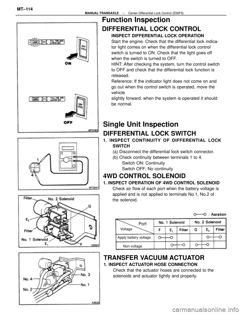
DIFFERENTIAL LOCK SWITCH
1. INSPECT CONTINUITY OF DIFFERENTIAL LOCK
SWITCH
(a) Disconnect the differential lock switch connector.
(b) Check continuity between terminals 1 to 4.
Switch ON: Continuity
Switch OFF: No continuity
4WD CONTROL SOLENOID
1. INSPECT OPERATION OF 4WD CONTROL SOLENOID
Check air flow of each port when the battery voltage is
applied and is not applied to terminals No.1, No.2 of
the solenoid.
Function Inspection
DIFFERENTIAL LOCK CONTROL
INSPECT DIFFERENTIAL LOCK OPERATION
Start the engine. Check that the differential lock indica-
tor light comes on when the differential lock control
switch is turned to ON. Check that the light goes off
when the switch is turned to OFF.
HINT: After checking the system, turn the control switch
to OFF and check that the differential lock function is
released.
Reference: If the indicator light does not come on and
go out when the control switch is operated, move the
vehicle
slightly forward. when the system is operated it should
be normal.
TRANSFER VACUUM ACTUATOR
1. INSPECT ACTUATOR HOSE CONNECTION
Check that the actuator hoses are connected to the
solenoids and actuator tightly and properly.
Apply battery voltage
Non voltage Voltage
Port
± MANUAL TRANSAXLECenter Differential Lock Control (E56F5)MT±114
Page 2045 of 2389

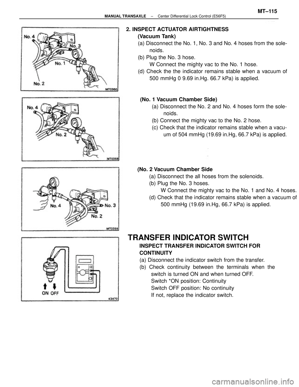
TRANSFER INDICATOR SWITCH
INSPECT TRANSFER INDICATOR SWITCH FOR
CONTINUITY
(a) Disconnect the indicator switch from the transfer.
(b) Check continuity between the terminals when the
switch is turned ON and when turned OFF.
Switch *ON position: Continuity
Switch OFF position: No continuity
If not, replace the indicator switch. 2. INSPECT ACTUATOR AIRTIGHTNESS
(Vacuum Tank)
(a) Disconnect the No. 1, No. 3 and No. 4 hoses from the sole-
noids.
(b) Plug the No. 3 hose.
W Connect the mighty vac to the No. 1 hose.
(d) Check the the indicator remains stable when a vacuum of
500 mmHg 0 9.69 in.Hg. 66.7 kPa) is applied.
(No. 2 Vacuum Chamber Side
(a) Disconnect the all hoses from the solenoids.
(b) Plug the No. 3 hoses.
W Connect the mighty vac to the No. 1 and No. 4 hoses.
(d) Check that the indicator remains stable when a vacuum of
500 mmHg (19.69 in.Hg, 66.7 kPa) is applied. (No. 1 Vacuum Chamber Side)
(a) Disconnect the No. 2 and No. 4 hoses form the sole-
noids.
(b) Connect the mighty vac to the No. 2 hose.
(c) Check that the indicator remains stable when a vacu-
um of 504 mmHg (19.69 in.Hg, 66.7 kPa) is applied.
± MANUAL TRANSAXLECenter Differential Lock Control (E56F5)MT±115
Page 2062 of 2389
2. REMOVE DIFFERENTIAL SIDE GEAR INTERMEDIATE
SHAFT
(a) Screw in a suitable bolt with washer into the side gear
intermediate shaft.
(b) Using SST, remove the side gear intermediate shaft.
SST 09910±00015
REMOVAL OF COMPONENT PARTS
(See pages MT± 118 to MT± 120)
1. REMOVE TRANSFER ASSEMBLY
(a) Remove the three bolts and five nuts.
(b) Using a plastic hammer, remove the transfer assembly
from the transaxle.
B. REMOVE SPEEDOMETER DRIVEN GEAR
6. REMOVE NO.2 SELECTING BELLCRANK WITH
SELECTING BELLCRANK SUPPORT 4. REMOVE BACK±UP LIGHT SWITCH
(a) Remove the back±up light switch.
(b) Remove the gasket from the back±up light switch. 3. REMOVE RELEASE FORK, BEARING AND BOOT
± MANUAL TRANSAXLERemoval of Component PartsMT±121
Page 2070 of 2389
(b) Lift up the differential case assembly, remove the output
shaft assembly. 32. REMOVE INPUT AND OUTPUT SHAFT ASSEMBLY
(a) Leaning the output shaft to the differential side,
remove the input shaft assembly.
33. REMOVE DIFFERENTIAL CASE ASSEMBLY
(a) Remove the oil pump drive gear.
34. REMOVE MAGNET FROM TRANSAXLE CASE(b) Remove the differential case assembly.
± MANUAL TRANSAXLERemoval of Component PartsMT±129
Page 2085 of 2389
Differential Case Assembly
(E56F5)
± MANUAL TRANSAXLEComponent Parts (Differential Case Assembly E56F5)MT±155
Page 2086 of 2389
DISASSEMBLY OF DIFFERENTIAL CASE
1. REMOVE DIFFERENTIAL CASE
(a) Remove the sixteen bolts.
2. REMOVE RING GEAR
(a) Place the matchmarks on both the differential No.2
case and ring gear.
(b) Using a plastic hammer, tap out the ring gear.
3. REMOVE NO.2 DIFFERENTIAL SIDE GEAR THRUST
WASHER AND CONICAL SPRING WASHER(b) Remove the differential No.2 case up
ward.
± MANUAL TRANSAXLEComponent Parts (Differential Case Assembly E56F5)MT±156
Page 2087 of 2389
5. DISASSEMBLE FRONT DIFFERENTIAL CASE
ASSEMBLY
(a) Remove the front differential side gear together with
thrust washer.
(b) Remove the front differential side gear thrust washer
from the side gear.
(c) Using snap ring pliers, remove the snap ring.
HINT: Before removing the shaft snap ring, wrap
vinyl tape around the case prevent the it from dam-
age.
(d) Remove the spacer.
(e) Remove the No.2 pinion shaft, two pinion shafts,
pinion holder, four differential pinions, four thrust
washers, front differential side gear and thrust
washer from the front differential case. 4. REMOVE FRONT DIFFERENTIAL CASE ASSEMBLY
± MANUAL TRANSAXLEComponent Parts (Differential Case Assembly E56F5)MT±157