Page 2096 of 2389

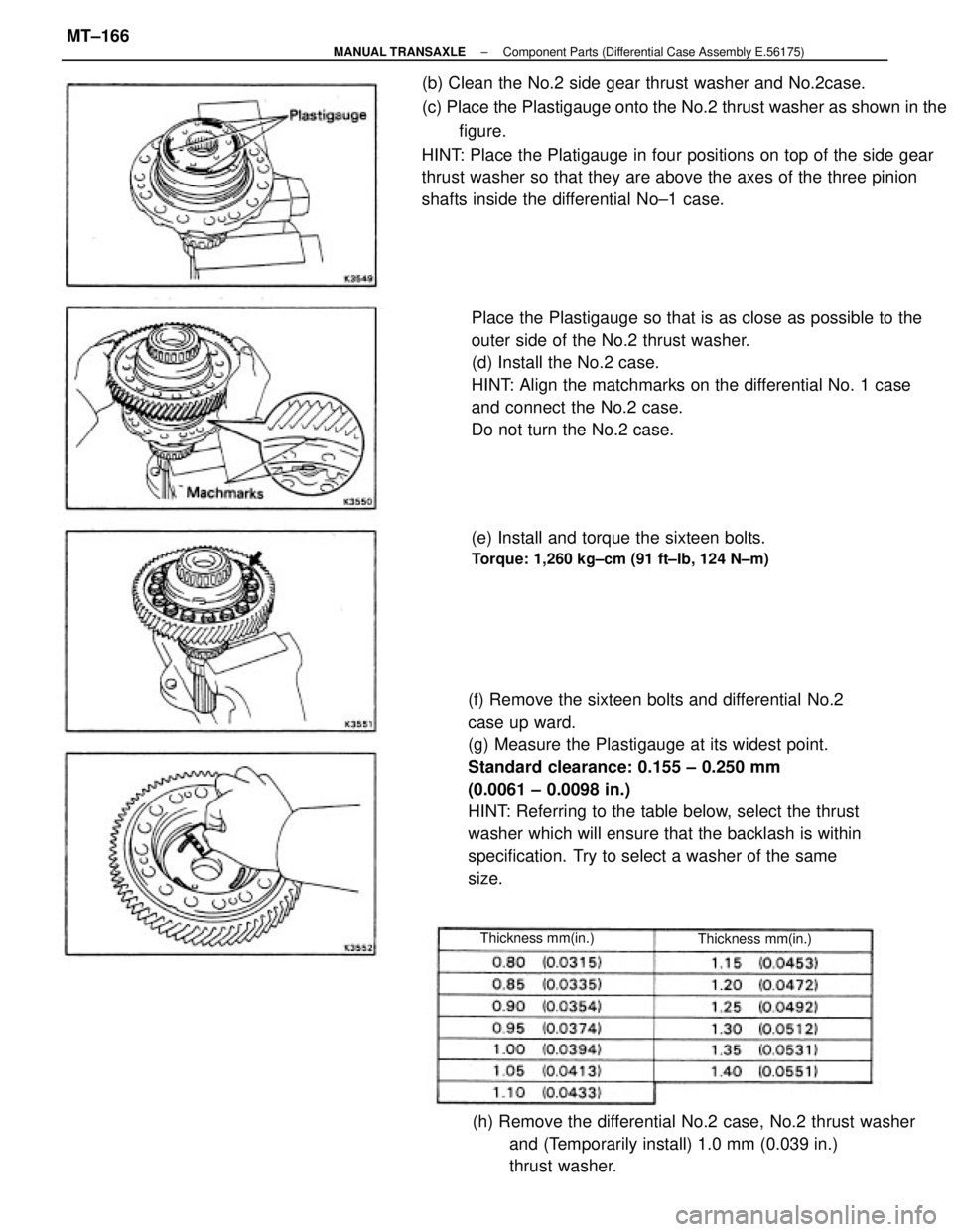
(f) Remove the sixteen bolts and differential No.2
case up ward.
(g) Measure the Plastigauge at its widest point.
Standard clearance: 0.155 ± 0.250 mm
(0.0061 ± 0.0098 in.)
HINT: Referring to the table below, select the thrust
washer which will ensure that the backlash is within
specification. Try to select a washer of the same
size. (b) Clean the No.2 side gear thrust washer and No.2case.
(c) Place the Plastigauge onto the No.2 thrust washer as shown in the
figure.
HINT: Place the Platigauge in four positions on top of the side gear
thrust washer so that they are above the axes of the three pinion
shafts inside the differential No±1 case.
Place the Plastigauge so that is as close as possible to the
outer side of the No.2 thrust washer.
(d) Install the No.2 case.
HINT: Align the matchmarks on the differential No. 1 case
and connect the No.2 case.
Do not turn the No.2 case.
(h) Remove the differential No.2 case, No.2 thrust washer
and (Temporarily install) 1.0 mm (0.039 in.)
thrust washer. (e) Install and torque the sixteen bolts.
Torque: 1,260 kg±cm (91 ft±Ib, 124 N±m)
Thickness mm(in.) Thickness mm(in.)
± MANUAL TRANSAXLEComponent Parts (Differential Case Assembly E.56175)MT±166
Page 2097 of 2389
12. INSTALL TRANSMISSION CASE
(a) Install the transmission case.
HINT: If necessary, tap on the case with a plastic ham-
mer.
(b) Install and torque the seventeen bolts.
Torque: 300 kg±cm (22 ft±Ib, 29 N±m)
10. INSTALL DIFFERENTIAL NO.2 CASE
(a) Install the conical spring washer and No.2 side gear
thrust washer (Previously selected).
HINT: Be careful not to mistake the direction of conical
spring washer.
(a) Install the differential No.2 case to the No. 1
case.
HINT: Align the matchmarks on the differential No.1
case and connect the N.2 case.
11. INSTALL DIFFERENTIAL CASE ASSEMBLY
Install the differential case assembly ±to the transaxle
case.(c) Install and torque the sixteen bolts.
Torque: 1,260 kg±cm (91 ft±ib, 124 N±m)
± MANUAL TRANSAXLEComponent Parts (Differential Case Assembly E5SF5)MT±167
Page 2098 of 2389
13. ADJUST DIFFERENTIAL SIDE BEARING PRELOAD
(a) Turn the differential case assembly counterclockwise and clock-
wise several time.
(b) Using a spring tension gauge, measure the differential case as-
sembly preload.
Preload (at starting)
New bearing
3.2 ± 6.3 kg
(7.1 ±13.9 lb,31.4±61.8N)
Reused bearing
2.0 ± 4.0 kg
(4.4±8.81b,19.6±39.2N)
If the preload is not within specification, select the thrust
washers.
HINT: The preload will change about 2.4 kg (5.3 Ib, 23.5 N) with
each shim thinness.
14. REMOVE TRANSMISSION CASE
Remove the seventeen bolts and tap off the case with a
plastic hammer.
15. REMOVE DIFFERENTIAL CASE ASSEMBLY
Thickness mm (in.) Thickness mm (in.)
Mark Mark
± MANUAL TRANSAXLEComponent Parts (Differential Case Assembly E5SF5)MT±168
Page 2102 of 2389
7. INSTALL INPUT SHAFT ASSEMBLY
Leaning the output shaft assembly to the differential
case side, install the input shaft assembly.
HINT: When you install the input shaft assy, be careful
not to scratch the oil seal. B. INSTALL OUTPUT SHAFT ASSEMBLY
Lifting the differential case assembly, install the output
shaft assembly. 4. INSTALL DIFFERENTIAL CASE ASSEMBLY3. INSTALL MAGNET TO TRANSAXLE CASE
S. INSTALL OIL PUMP DRIVE GEAR
± MANUAL TRANSAXLE'.Installation of Component PartsMT±193
Page 2112 of 2389

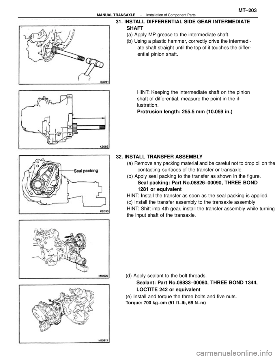
32. INSTALL TRANSFER ASSEMBLY
(a) Remove any packing material and be careful not to drop oil on the
contacting surfaces of the transfer or transaxle.
(b) Apply seal packing to the transfer as shown in the figure.
Seal packing: Part No.08826±00090, THREE BOND
1281 or equivalent
HINT: Install the transfer as soon as the seal packing is applied.
(c) Install the transfer assembly to the transaxle assembly
HINT: Shift into 4th gear, install the transfer assembly while turning
the input shaft of the transaxle. 31. INSTALL DIFFERENTIAL SIDE GEAR INTERMEDIATE
SHAFT
(a) Apply MP grease to the intermediate shaft.
(b) Using a plastic hammer, correctly drive the intermedi-
ate shaft straight until the top of it touches the differ-
ential pinion shaft.
(d) Apply sealant to the bolt threads.
Sealant: Part No.08833±00080, THREE BOND 1344,
LOCTITE 242 or equivalent
(e) Install and torque the three bolts and five nuts.
Torque: 700 kg±cm (51 ft±Ib, 69 N±m)
HINT: Keeping the intermediate shaft on the pinion
shaft of differential, measure the point in the il-
lustration.
Protrusion length: 255.5 mm (10.059 in.)
± MANUAL TRANSAXLEInstallation of Component PartsMT±203
Page 2115 of 2389
DISASSEMBLY OF TRANSFER COMPONENT
PARTS
1. REMOVE TRANSFER VACUUM ACTUATOR
(a) Remove the four bolts.
(b) Remove the actuator bracket and stiffener center plate.
3. REMOVE DIFFERENTIAL LOCK SHIFT FORK SHAFT
(a) Remove transfer indicator switch.
(b) Using SST, remove the plug.
SST 09313±30021 (c) Remove the three bolts.
(d) Remove the vacuum actuator.
(c) Using SST, remove the plug.
SST 09043±38100 2. REMOVE DUST BOOT
± MANUAL TRANSAXLEComponent Parts (Transfer Assembly E56F5)MT±170
Page 2122 of 2389
21. INSPECT TRANSFER VACUUM ACTUATOR
(a) the push rod.
(b) Apply a vacuum of 500 mmHg to port Y1 and Y2.
Move in the push rod and measure the push rod strake.
Push rod strake: 16.5 mm (0.650 in.) or more
(c) Apply a vacuum of 500 mmHg to port Y3. Check that no remain
the vacuum in actuator.
If not, replace the actuator.
(d) After the check, apply a vacuum of 500 mmHg to port Y of the ac-
tuator (Put the differential lock on the free side). 20. MEASURE CLEARANCE OF DIFFERENTIAL LOCK
SHIFT FORK AND SLEEVE
Measure the clearance between the shift fork and
sleeve.
Maximum clearance: 1.0 mm (0.039 in.)(d) Using. SST and a press, install the outer race.
SST 09316±60010 (09316±00010, 09316±00060)
± MANUAL TRANSAXLEComponent Parts (Transfer Assembly E56F5)MT±177
Page 2127 of 2389

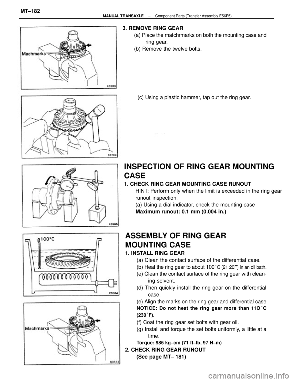
ASSEMBLY OF RING GEAR
MOUNTING CASE
1. INSTALL RING GEAR
(a) Clean the contact surface of the differential case.
(b) Heat the ring gear to about 100
°C (21 20F) in an oil bath.
(e) Clean the contact surface of the ring gear with clean-
ing solvent.
(d) Then quickly install the ring gear on the differential
case.
(e) Align the marks on the ring gear and differential case
NOTICE: Do not heat the ring gear more than 11O°C
(230°F).
(f) Coat the ring gear set bolts with gear oil.
(g) Install and torque the set bolts uniformly, a little at a
time.
Torque: 985 kg±cm (71 ft±Ib, 97 N±m)
2. CHECK RING GEAR RUNOUT
(See page MT± 181)
INSPECTION OF RING GEAR MOUNTING
CASE
1. CHECK RING GEAR MOUNTING CASE RUNOUT
HINT: Perform only when the limit is exceeded in the ring gear
runout inspection.
(a) Using a dial indicator, check the mounting case
Maximum runout: 0.1 mm (0.004 in.) 3. REMOVE RING GEAR
(a) Place the matchrmarks on both the mounting case and
ring gear.
(b) Remove the twelve bolts.
(c) Using a plastic hammer, tap out the ring gear.
± MANUAL TRANSAXLEComponent Parts (Transfer Assembly E56F5)MT±182