Page 1931 of 2389

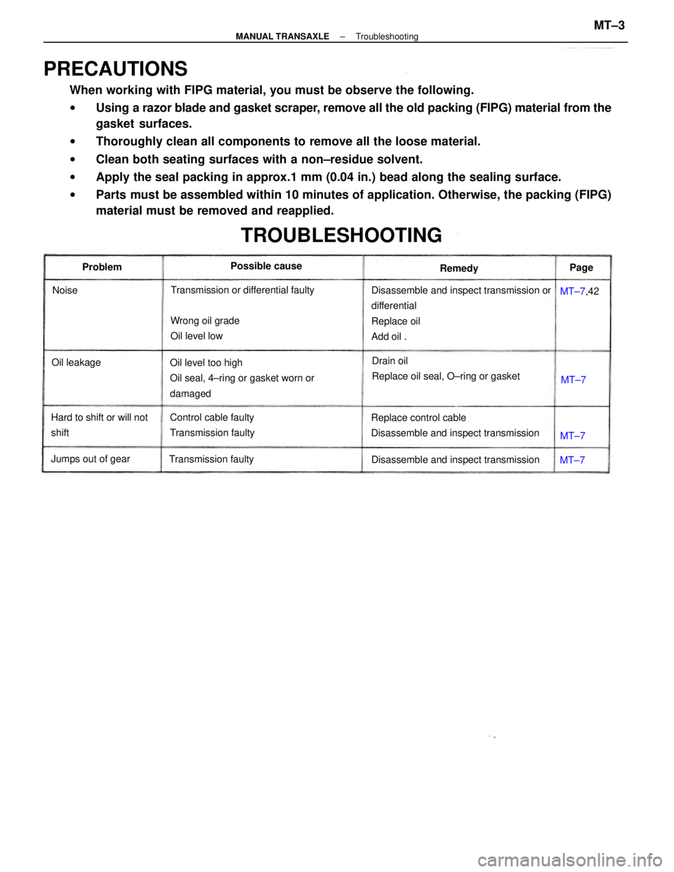
PRECAUTIONS
When working with FIPG material, you must be observe the following.
wUsing a razor blade and gasket scraper, remove all the old packing (FIPG) material from the
gasket surfaces.
wThoroughly clean all components to remove all the loose material.
wClean both seating surfaces with a non±residue solvent.
wApply the seal packing in approx.1 mm (0.04 in.) bead along the sealing surface.
wParts must be assembled within 10 minutes of application. Otherwise, the packing (FIPG)
material must be removed and reapplied.
Disassemble and inspect transmission or
differential
Replace oil
Add oil .
Oil level too high
Oil seal, 4±ring or gasket worn or
damaged
Replace control cable
Disassemble and inspect transmissionDrain oil
Replace oil seal, O±ring or gasket
TROUBLESHOOTING
Control cable faulty
Transmission faulty
Disassemble and inspect transmission Transmission or differential faulty
Hard to shift or will not
shiftWrong oil grade
Oil level low
Transmission faulty Jumps out of gearPossible cause
Oil leakageMT±7,42 Problem
Remedy
Noise
MT±7MT±7MT±7Page
± MANUAL TRANSAXLETroubleshootingMT±3
Page 1940 of 2389
18. REMOVE REVERSE SHIFT ARM
(a) Shift the fork shaft into reverse.
(b) Remove the two bolts and pull off the reverse shift arm.
19. REMOVE REVERSE IDLER GEAR AND SHAFT
Pull out the shaft. 13. REMOVE REAR BEARING RETAINER
14. REMOVE BEARING SNAP RINGS
Using snap ring pliers, remove the two snap rings.
17. REMOVE TRANSMISSION CASE
Remove the seventeen bolts and tap off the case with
a plastic hammer. 16. REMOVE DIFFERENTIAL SIDE BEARING RETAINER
AND SHIM 15. REMOVE REVERSE IDLER GEAR SHAFT¿¿ LOCK
BOLT
± MANUAL TRANSAXLES51 TransmissionMT±12
Page 1942 of 2389
26. MEASURE THIRD AND FOURTH GEAR THRUST
CLEARANCE
Using a feeler gauge, measure the thrust clearance.
Standard clearance:
3rd gear 0.10 ± 0.25 mm
(0.0039 ± 0.0098 in.)
4th gear 0.20 ± 0.45 mm
(0.0079 ± 0.0177 in.)
Maximum clearance:
3rd gear 0.30 mm (0.0118 in.)
4th gear 0.50 mm (0.0197 in.)
27. REMOVE SNAP RING FROM INPUT SHAFT
Using two screwdrivers and a hammer, tap out the
snap ring.
28. REMOVE RADIAL BALL BEARING, FOURTH GEAR,
NEEDLE ROLLER BEARINGS, SYNCHRONIZER
RING AND SPACER FROM INPUT SHAFT
(a) Using a press, remove the radial ball bearing and 4th gear.
(b) Remove the needle roller bearings, synchronizer ring and
spacer. (b) Using a pin punch and hammer, drive out the slotted
spring pin.
(e) Pull out the shaft.
24. REMOVE DIFFERENTIAL ASSEMBLY
25. REMOVE MAGNET 23. REMOVE NO. 2 FORK SHAFT
(a) Using SST, remove the straight screw plug.
SST 09312±30021
± MANUAL TRANSAXLES51 TransmissionMT±14
Page 1959 of 2389

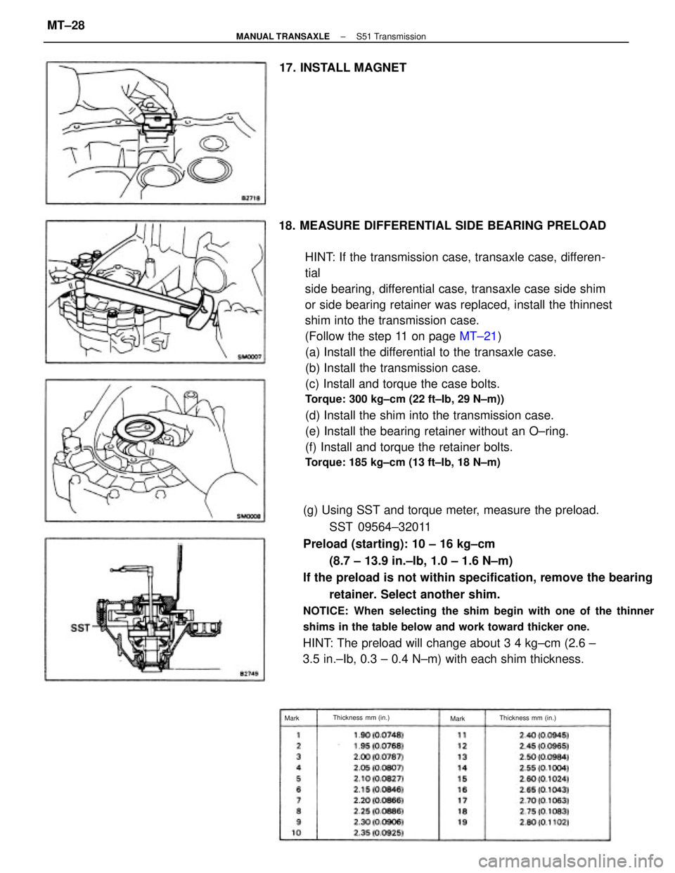
18. MEASURE DIFFERENTIAL SIDE BEARING PRELOAD
HINT: If the transmission case, transaxle case, differen-
tial
side bearing, differential case, transaxle case side shim
or side bearing retainer was replaced, install the thinnest
shim into the transmission case.
(Follow the step 11 on page MT±21)
(a) Install the differential to the transaxle case.
(b) Install the transmission case.
(c) Install and torque the case bolts.
Torque: 300 kg±cm (22 ft±Ib, 29 N±m))
(d) Install the shim into the transmission case.
(e) Install the bearing retainer without an O±ring.
(f) Install and torque the retainer bolts.
Torque: 185 kg±cm (13 ft±Ib, 18 N±m)
(g) Using SST and torque meter, measure the preload.
SST 09564±32011
Preload (starting): 10 ± 16 kg±cm
(8.7 ± 13.9 in.±Ib, 1.0 ± 1.6 N±m)
If the preload is not within specification, remove the bearing
retainer. Select another shim.
NOTICE: When selecting the shim begin with one of the thinner
shims in the table below and work toward thicker one.
HINT: The preload will change about 3 4 kg±cm (2.6 ±
3.5 in.±Ib, 0.3 ± 0.4 N±m) with each shim thickness. 17. INSTALL MAGNET
Thickness mm (in.)
Thickness mm (in.)
Mark
Mark
± MANUAL TRANSAXLES51 TransmissionMT±28
Page 1970 of 2389
DIFFERENTIAL
REMOVAL OF DIFFERENTIAL
1. REMOVE TRANSAXLE
(See pages MT±4 to 6)
2. REMOVE DIFFERENTIAL ASSEMBLY
(See steps 1 to 24 on pages MT±10 to 14)
REPLACEMENT OF DIFFERENTIAL
(See pages AT±158 to 160)
ADJUSTMENT OF DIFFERENTIAL CASE
(See pages AT±161, 162)
INSTALLATION OF DIFFERENTIAL
1. INSTALL DIFFERENTIAL ASSEMBLY TO TRANSAXLE
(See steps 18 to 37 and 39 to 48 on pages MT±28 to 37)
2. INSTALL TRANSAXLE
(See pages MT±38 to 40)
± MANUAL TRANSAXLEDifferentialMT±42
Page 1972 of 2389

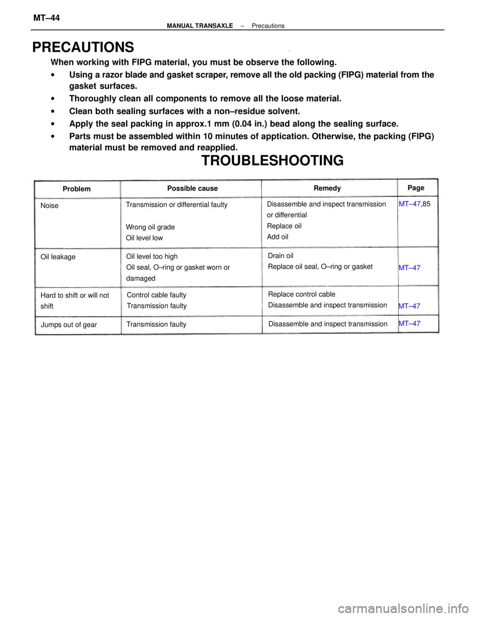
PRECAUTIONS
When working with FIPG material, you must be observe the following.
wUsing a razor blade and gasket scraper, remove all the old packing (FIPG) material from the
gasket surfaces.
wThoroughly clean all components to remove all the loose material.
wClean both sealing surfaces with a non±residue solvent.
wApply the seal packing in approx.1 mm (0.04 in.) bead along the sealing surface.
wParts must be assembled within 10 minutes of apptication. Otherwise, the packing (FIPG)
material must be removed and reapplied.
Disassemble and inspect transmission
or differential
Replace oil
Add oil
Oil level too high
Oil seal, O±ring or gasket worn or
damaged
Replace control cable
Disassemble and inspect transmission Drain oil
Replace oil seal, O±ring or gasket
TROUBLESHOOTING
Control cable faulty
Transmission faulty
Disassemble and inspect transmission Transmission or differential faulty
Hard to shift or will not
shiftWrong oil grade
Oil level low
Transmission faulty
Jumps out of gearPossible cause
Oil leakageMT±47,85 ProblemRemedy
MT±47 MT±47MT±47 NoisePage
± MANUAL TRANSAXLEPrecautionsMT±44
Page 1973 of 2389

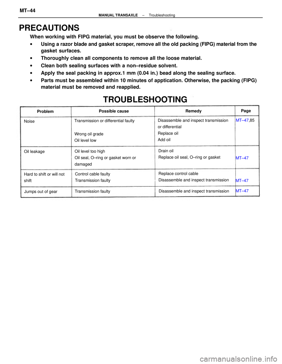
PRECAUTIONS
When working with FIPG material, you must be observe the following.
wUsing a razor blade and gasket scraper, remove all the old packing (FIPG) material from the
gasket surfaces.
wThoroughly clean all components to remove all the loose material.
wClean both sealing surfaces with a non±residue solvent.
wApply the seal packing in approx.1 mm (0.04 in.) bead along the sealing surface.
wParts must be assembled within 10 minutes of apptication. Otherwise, the packing (FIPG)
material must be removed and reapplied.
Disassemble and inspect transmission
or differential
Replace oil
Add oil
Oil level too high
Oil seal, O±ring or gasket worn or
damaged
Replace control cable
Disassemble and inspect transmission Drain oil
Replace oil seal, O±ring or gasket
TROUBLESHOOTING
Control cable faulty
Transmission faulty
Disassemble and inspect transmission Transmission or differential faulty
Hard to shift or will not
shiftWrong oil grade
Oil level low
Transmission faulty
Jumps out of gearPossible cause
Oil leakageMT±47,85 ProblemRemedy
MT±47 MT±47MT±47 NoisePage
± MANUAL TRANSAXLETroubleshootingMT±44
Page 1991 of 2389
28. REMOVE SNAP RINGS
(a) Using two screwdrivers and a hammer, remove the
snap ring and reverse shift fork from the No.3 shift
fork shaft.
(b) Using two screwdrivers and a hammer, remove the
snap rings from the No.1, No.2 and No.3 shift fork
shafts. 27. REMOVE NO.3 SHIFT FORK SHAFT WITH REVERSE
SHIFT FORK AND NO.2 SHIFT FORK
(a) Pull out the No.3 shift fork shaft with reverse shift fork.
(b) Remove the No±2 shift fork.
29. REMOVE INPUT AND OUTPUT SHAFT ASSEMBLY
(a) Leaning the output shaft to the differential side,
remove the input shaft assembly.
(b) Lift up the differential case assembly, remove the
output shaft.
30. REMOVE DIFFERENTIAL ASSEMBLY
(a) Remove the oil pump drive gear.
± MANUAL TRANSAXLERemoval of Component PartsMT±56