Page 647 of 2389
(b) Remove any packing material on the contacting surfaces of
LH bearing retainer, transaxle case and carrier cover.
(c) Apply the seal packing to the transaxle case and carrier cover
as shown.
Seal packing: Part No. 08826±00090, THREE BOND
1281 or equivalent
HINT: Install the LH bearing retainer with ten minutes after ap-
plying seal packing.
(d) Install the LH bearing retainer.
(e) Coat the threads of bolts with sealer.
Sealer: Part No. 08833±00070, THREE BOND 1324
or equivalent
(f) Tighten the bolts.
Torque: 195 kg±cm (14 ft±Ib, 19 N±m)
(g) Snap down the bearings.
(h) Recheck the differential total preload.
(b) Using SST, driven in a new oil seal until its end is flush with the
surface of the LH bearing retainer.
SST 09223±15010 13. INSTALL NEW OIL SEAL
(a) Place the oil baffle onto the LH bearing retainer. 12. INSTALL LH BEARING RETAINER
(a) Remove the six bolts and LH bearing retainer.
± AUTOMATIC TRANSAXLEInstallation of Component Parts (A540E and A540H)AT±389
Page 665 of 2389
49. (A540H)
INSTALL DIFFERENTIAL SIDE GEAR INTERMEDIATE
SHAFT
(a) Install a new snap ring to the shaft groove.
(b) Using a plastic hammer, install the shaft. 48. INSTALL UNION AND ELBOW
(a) Install the new O±rings to the union and elbow.
(b) Install the union and elbow to the transaxle case.
Torque: 275 kg±cm (20 ft±Ib, 27 N±m)
HINT: Keeping the intermediate shaft on the pinion shaft of
differential, measure the point in the illustration.
Protrusion length (Reference): 255.5 mm 110.059 in.) HINT: Install the elbow at right angles to the bottom of
the transaxle case. 47. INSTALL MANUAL SHIT LEVER
± AUTOMATIC TRANSAXLEInstallation of Component Parts (A540E and A540H)AT±407
Page 666 of 2389
51. (A540H)
INSTALL TRANSFER ASSEMBLY
(a) Remove any packing material and be careful not to drop oil on
the contacting surfaces of the transfer and transaxle.
(b) Apply seal packing to the transaxle as shown in the illustration.
Seal packing: Part No. 08883±00090, Adhesive 1131,
THREE BOND 1131, Loctite 518, or equivalent
HINT: Install the transfer assembly as soon as the seal packing
is applied.
(e) Coat the threads of bolts with sealer.
Sealer: Part No. 08833±00070, THREE BOND 1324
or equivalent.
(d) Install and torque the five nuts and three bolts.
Torque: 700 kg±cm (51 ft±Ib, 69 N±m)
52. (A540H)
INSPECT MODE SELECT LEVER POSITION
After finishing inspection or repair the transaxle, be
sure the select lever position to FREE mode and at-
tach the lock bolt. 50. (A540 H )
INSTALL APPLY GASKET
Install a new apply gasket to the differential carrier cover.
± AUTOMATIC TRANSAXLEInstallation of Component Parts (A540E and A540H)AT±408
Page 1383 of 2389

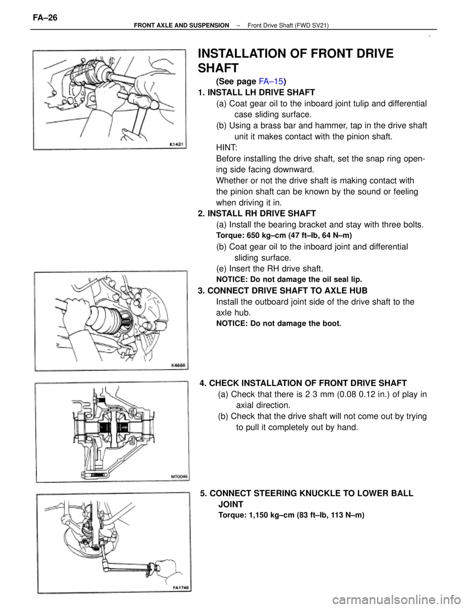
INSTALLATION OF FRONT DRIVE
SHAFT
(See page FA±15)
1. INSTALL LH DRIVE SHAFT
(a) Coat gear oil to the inboard joint tulip and differential
case sliding surface.
(b) Using a brass bar and hammer, tap in the drive shaft
unit it makes contact with the pinion shaft.
HINT:
Before installing the drive shaft, set the snap ring open-
ing side facing downward.
Whether or not the drive shaft is making contact with
the pinion shaft can be known by the sound or feeling
when driving it in.
2. INSTALL RH DRIVE SHAFT
(a) Install the bearing bracket and stay with three bolts.
Torque: 650 kg±cm (47 ft±Ib, 64 N±m)
(b) Coat gear oil to the inboard joint and differential
sliding surface.
(e) Insert the RH drive shaft.
NOTICE: Do not damage the oil seal lip.
3. CONNECT DRIVE SHAFT TO AXLE HUB
Install the outboard joint side of the drive shaft to the
axle hub.
NOTICE: Do not damage the boot.
4. CHECK INSTALLATION OF FRONT DRIVE SHAFT
(a) Check that there is 2 3 mm (0.08 0.12 in.) of play in
axial direction.
(b) Check that the drive shaft will not come out by trying
to pull it completely out by hand.
5. CONNECT STEERING KNUCKLE TO LOWER BALL
JOINT
Torque: 1,150 kg±cm (83 ft±Ib, 113 N±m)
± FRONT AXLE AND SUSPENSIONFront Drive Shaft (FWD SV21)FA±26
Page 1386 of 2389

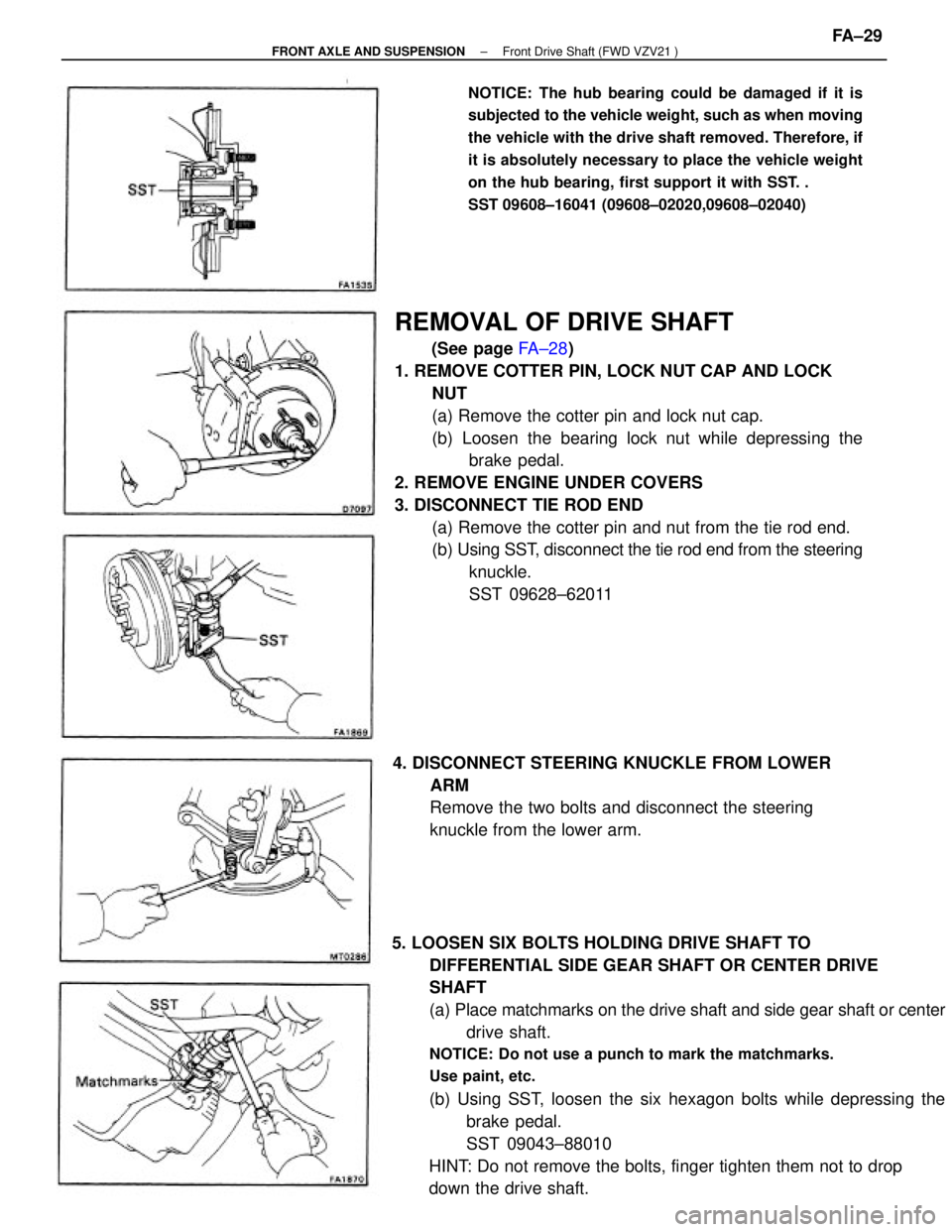
REMOVAL OF DRIVE SHAFT
(See page FA±28)
1. REMOVE COTTER PIN, LOCK NUT CAP AND LOCK
NUT
(a) Remove the cotter pin and lock nut cap.
(b) Loosen the bearing lock nut while depressing the
brake pedal.
2. REMOVE ENGINE UNDER COVERS
3. DISCONNECT TIE ROD END
(a) Remove the cotter pin and nut from the tie rod end.
(b) Using SST, disconnect the tie rod end from the steering
knuckle.
SST 09628±62011
5. LOOSEN SIX BOLTS HOLDING DRIVE SHAFT TO
DIFFERENTIAL SIDE GEAR SHAFT OR CENTER DRIVE
SHAFT
(a) Place matchmarks on the drive shaft and side gear shaft or center
drive shaft.
NOTICE: Do not use a punch to mark the matchmarks.
Use paint, etc.
(b) Using SST, loosen the six hexagon bolts while depressing the
brake pedal.
SST 09043±88010
HINT: Do not remove the bolts, finger tighten them not to drop
down the drive shaft.
NOTICE: The hub bearing could be damaged if it is
subjected to the vehicle weight, such as when moving
the vehicle with the drive shaft removed. Therefore, if
it is absolutely necessary to place the vehicle weight
on the hub bearing, first support it with SST. .
SST 09608±16041 (09608±02020,09608±02040)
4. DISCONNECT STEERING KNUCKLE FROM LOWER
ARM
Remove the two bolts and disconnect the steering
knuckle from the lower arm.
± FRONT AXLE AND SUSPENSIONFront Drive Shaft (FWD VZV21 )FA±29
Page 1388 of 2389
7. (LH SIDE)
DRAIN OUT GEAR OIL
8. (LH SIDE)
REMOVE SIDE GEAR SHAFT FROM TRANSAXLE
(a) In order to install the side gear shaft, push the side gear
shaft to the differential.
Measure and note the distance between the trans-
axle case and the side gear shaft.
(b) Using SST, drive out the side gear shaft.
SST 09520±32012
9. IF NECESSARY, REPLACE SIDE GEAR SHAFT OIL
SEAL
(a) Using SST, pull out the oil seal from the case.
SST 09308±00010
(b) Using SST and a hammer, tap in a new oil seal.
SST LH side
09223±15010
HINT: Coat the oil seal lip with MP grease.
SST RH side
09316±60010 (09316±00010)
HINT: Coat the oil seal lip with MP
grease.
± FRONT AXLE AND SUSPENSIONFront Drive Shaft (FWD VZV21 )FA±31
Page 1395 of 2389

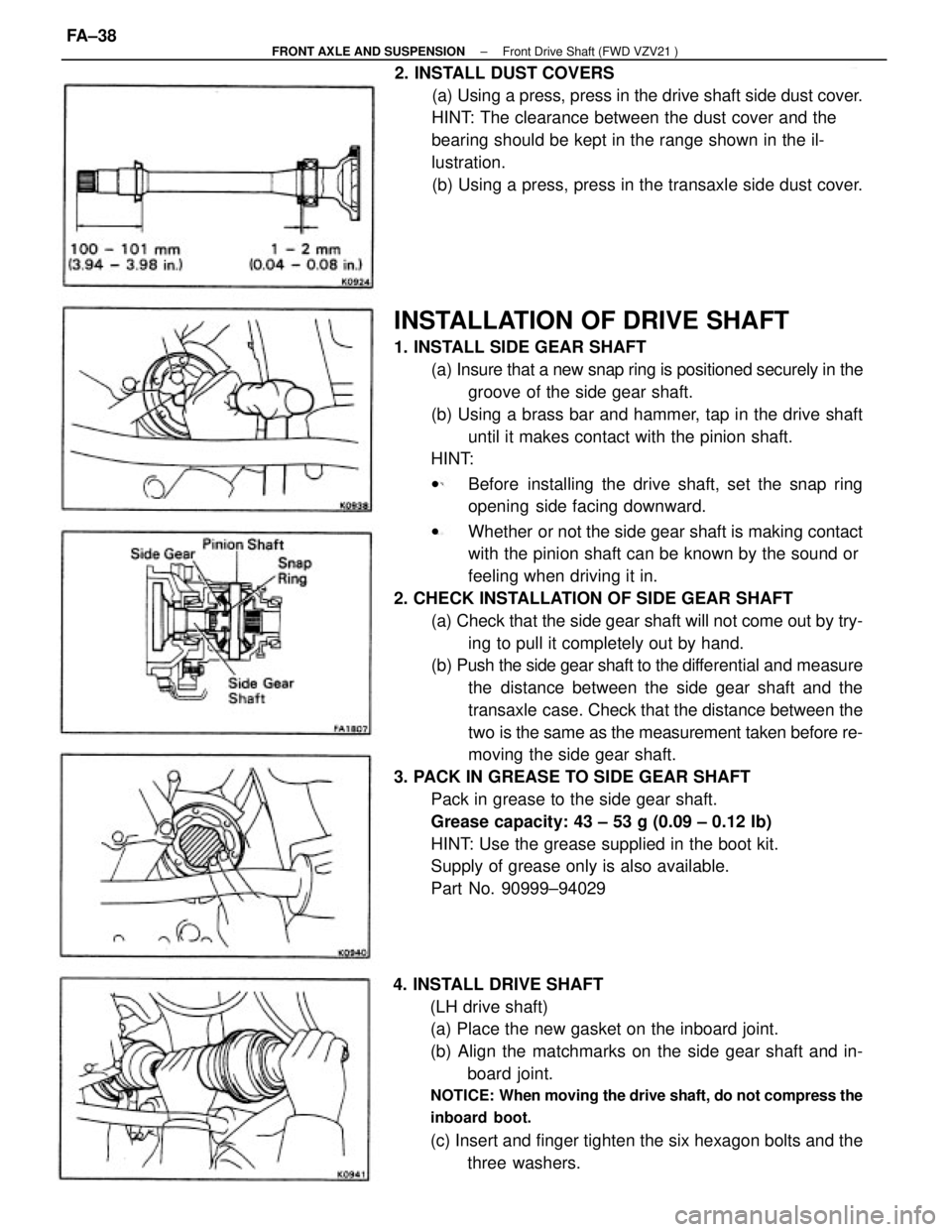
INSTALLATION OF DRIVE SHAFT
1. INSTALL SIDE GEAR SHAFT
(a) Insure that a new snap ring is positioned securely in the
groove of the side gear shaft.
(b) Using a brass bar and hammer, tap in the drive shaft
until it makes contact with the pinion shaft.
HINT:
wBefore installing the drive shaft, set the snap ring
opening side facing downward.
wWhether or not the side gear shaft is making contact
with the pinion shaft can be known by the sound or
feeling when driving it in.
2. CHECK INSTALLATION OF SIDE GEAR SHAFT
(a) Check that the side gear shaft will not come out by try-
ing to pull it completely out by hand.
(b) Push the side gear shaft to the differential and measure
the distance between the side gear shaft and the
transaxle case. Check that the distance between the
two is the same as the measurement taken before re-
moving the side gear shaft.
3. PACK IN GREASE TO SIDE GEAR SHAFT
Pack in grease to the side gear shaft.
Grease capacity: 43 ± 53 g (0.09 ± 0.12 Ib)
HINT: Use the grease supplied in the boot kit.
Supply of grease only is also available.
Part No. 90999±94029
4. INSTALL DRIVE SHAFT
(LH drive shaft)
(a) Place the new gasket on the inboard joint.
(b) Align the matchmarks on the side gear shaft and in-
board joint.
NOTICE: When moving the drive shaft, do not compress the
inboard boot.
(c) Insert and finger tighten the six hexagon bolts and the
three washers. 2. INSTALL DUST COVERS
(a) Using a press, press in the drive shaft side dust cover.
HINT: The clearance between the dust cover and the
bearing should be kept in the range shown in the il-
lustration.
(b) Using a press, press in the transaxle side dust cover.
± FRONT AXLE AND SUSPENSIONFront Drive Shaft (FWD VZV21 )FA±38
Page 1864 of 2389

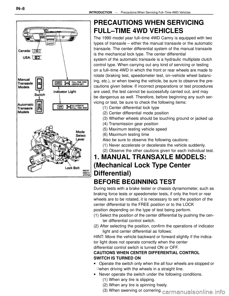
PRECAUTIONS WHEN SERVICING
FULL±TIME 4WD VEHICLES
The 1990 model year full±time 4WD Camry is equipped with two
types of transaxle ± either the manual transaxle or the automatic
transaxle. The center differential system of the manual transaxle
is the mechanical lock type. The center differential
system of the automatic transaxle is a hydraulic multiplate clutch
control type. When carrying out any kind of servicing or testing
on a full±time 4WD in which the front or rear wheels are made to
rotate (braking test, speedometer test, on±vehicle wheel balanc-
ing, etc.), or when towing the vehicle, be sure to observe the pre-
cautions given below. If incorrect preparations or test procedures
are used, the test cannot be successfully carried out, and may
be dangerous as well. Therefore, before beginning any such ser-
vicing or test, be sure to check the following items:
(1) Center differential lock type
(2) Center differential mode position
(3) Whether wheels should be touching ground or jacked up
(4) Transmission gear position
(5) Maximum testing vehicle speed
(6) Maximum testing time
Also be sure to observe the following cautions:
(1) Never accelerate or decelerate the vehicle suddenly.
(2) Observe the other cautions given for each individual test.
1. MANUAL TRANSAXLE MODELS:
(Mechanical Lock Type Center
Differential)
BEFORE BEGINNING TEST
During tests with a brake tester or chassis dynamometer, such as
braking force tests or speedometer tests, if only the front or rear
wheels are to be rotated, it is necessary to set the position of the
center differential to the FREE position or to the LOCK
position depending on the type of test being perform.
(1) Select the position of the center differential by pushing the cen-
ter differential control switch.
(2) After selecting the position, confirm the operations of indicator
light and center differential as follows:
HINT: Move the vehicle backward or forward slightly if the indica-
tor light does not operate correctly when the center
differential control switch is turned ON or OFF.
CAUTIONS WHEN CENTER DIFFERENTIAL CONTROL
SWITCH IS TURNED ON
wOperate the switch only when the all four wheels are stopped or
when driving with the wheels in a straight line.
wNever operate the switch under the following conditions.
(1) When any tire is slipping.
(2) When any tire is spinning freely.
(3) When swerving or cornering.
± INTRODUCTIONPrecautions When Servicing Full±Time 4WD VehiclesIN±8