Page 2224 of 2389
Fuel tank band x Body
Cold start injector x Air intake chamber
Cold start injector pipe x Cold start injector
Cold start injector pipe x Delivery pipe
Fuel pressure regulator X Delivery pipe
Fuel return pipe x Fuel pressure regulator
Delivery pipe x Cylinder head
Throttle body x Air intake chamberFuel evaporation vent tube x Fuel tank 4WD
Fuel inlet pipe x Fuel tankFuel sender gauge
Fuel pump X Fuel tank
Specifications (Cont'd)
Torque Specifications
Coolant temp. 805C (1765F) Intake air temp. 205C (685F) Measuring plate fully closed
Measuring plate fully openThrottle valve fully closed
Throttle valve fully closedThrottle valve fully closedThrottle valve fully closed
Throttle valve fully openThrottle valve fully open
* 1 w/o ECT *2 w/ ECT Throttle valve openThrottle valve open
Part tightened ECU (cont'd) Resistance
Condition
Fuel line
± SERVICE SPECIFICATIONSEFI System (3S±FE)A±13
Page 2227 of 2389
HINT:
wPerform all voltage and resistance measurements with the ECU connected.
wVerify that the battery voltage is 11 V or above with the ignition switch is ON.
No trouble (ºCHECKº' engine warning light off) and
engine running
Specifications (Cont'd)
Stop light SW ON (Brake pedal depressed)Check connector TE1 ± E1 not connected
Check connector TE1 ± Et connected
Shift position P or N range
Ex shift position P or N rangeIntake air temp. 205C (685F) Measuring plate fully closed
Coolant temp. 605C (1765F) Measuring plate fully open Throttle valve fully closed
Heater blower SW ON Air conditioning ONThrottle valve open
Throttle valve open
Cranking or idling Heater resistance
STD voltage (V) Oxygen
sensor
IG SW ON
IG SW ONIG SW ON
IG SW ONIG SW ON
IG SW ONCranking Terminals
Condition Voltage
Idling
*1 w/ rpm ECU
± SERVICE SPECIFICATIONSEFI System (2VZ±FE)A±15
Page 2228 of 2389

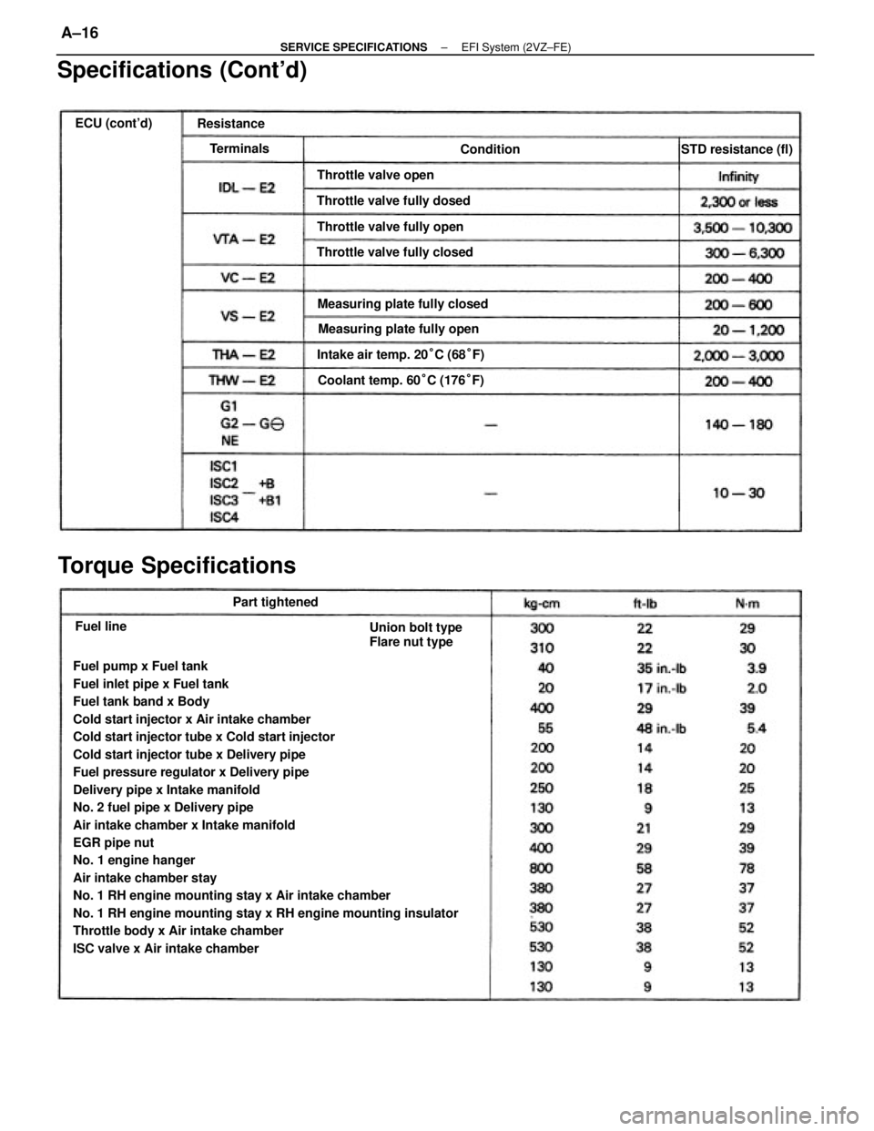
Fuel pump x Fuel tank
Fuel inlet pipe x Fuel tank
Fuel tank band x Body
Cold start injector x Air intake chamber
Cold start injector tube x Cold start injector
Cold start injector tube x Delivery pipe
Fuel pressure regulator x Delivery pipe
Delivery pipe x Intake manifold
No. 2 fuel pipe x Delivery pipe
Air intake chamber x Intake manifold
EGR pipe nut
No. 1 engine hanger
Air intake chamber stay
No. 1 RH engine mounting stay x Air intake chamber
No. 1 RH engine mounting stay x RH engine mounting insulator
Throttle body x Air intake chamber
ISC valve x Air intake chamber
Specifications (Cont'd)
Torque Specifications
Intake air temp. 20°C (68°F) Measuring plate fully closed
Coolant temp. 60°C (176°F)
Union bolt type
Flare nut type Measuring plate fully open Throttle valve fully dosed
Throttle valve fully closedThrottle valve fully open Throttle valve openSTD resistance (fl)
Part tightened ECU (cont'd)
Resistance
Terminals
Condition
Fuel line
± SERVICE SPECIFICATIONSEFI System (2VZ±FE)A±16
Page 2269 of 2389
Wheel lateral runout
Tie rod end left±right error
Hub bearing axial direction play
Ball joint vertial play
Ball joint rotation condition
Drive shaft standard length
(FWD/SV21 /TOYOTA type/LH)
(FWD/SV21 /TOYOTA type/RH)
(FWD/SV21 /GKN type/LH)
(FWD/SV21 /GKN type/RH)
( FVIJD/VZV21)
(4WD/M/T/LH)
(4WD/A/T/LH)
(4WD/M/T/RH)
FRONT AXLE AND SUSPENSION
Specifications
Wheel angle
(FWD/SV21 and 4WD)
(FWD/VZV21)(FWD/SV21 and 4WD)
( FWD/VZV21)
Less than 3.0 mm/m (0.118 in./3.3 ft) (FWD/SV21 )
(4WD)
(F1ND/VZV21 )
Front axle
and suspensionChassis groung
clearance
Steering axis inclination Cold tire
inflation
pressure
Front wheel
alignment
Outside wheel (Max.)
Inside wheel (Max.)Adjustment STD
Inspection STD
Side slipCamber
Caster Toe±in
± SERVICE SPECIFICATIONSFront Axle and SuspensionA±31
Page 2300 of 2389
SST (SPECIAL SERVICE TOOLS) (Cont'd)
NOTE: For reference to SSTs for the Air Conditioning System see page AC±15.
Remarks:
* 1 E52 and E56F5
* 2 Drive shaft dust cover
* 3 4WD only A.B.S. Actuator
Checker and
Sub±harness
A.B.S. Actuator
Checker Sheet ºAºBearing Remover
Attachment
Oil Pressure
Gauge SetBearing Remover
IllustrationPart Name
Universal Puller
Part No.Section
± SST AND SSMSST (Special Service Tools)C±20
Page 2302 of 2389

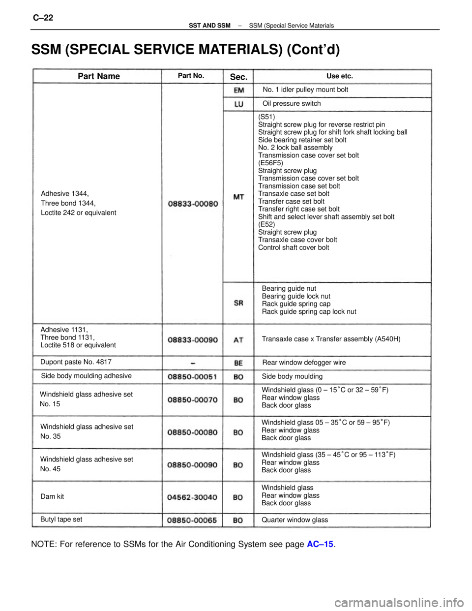
(S51)
Straight screw plug for reverse restrict pin
Straight screw plug for shift fork shaft locking ball
Side bearing retainer set bolt
No. 2 lock ball assembly
Transmission case cover set bolt
(E56F5)
Straight screw plug
Transmission case cover set bolt
Transmission case set bolt
Transaxle case set bolt
Transfer case set bolt
Transfer right case set bolt
Shift and select lever shaft assembly set bolt
(E52)
Straight screw plug
Transaxle case cover bolt
Control shaft cover bolt
SSM (SPECIAL SERVICE MATERIALS) (Cont'd)
Windshield glass (35 ± 45°C or 95 ± 113°F)
Rear window glass
Back door glass Windshield glass 05 ± 35°C or 59 ± 95°F)
Rear window glass
Back door glassWindshield glass (0 ± 15°C or 32 ± 59°F)
Rear window glass
Back door glass
NOTE: For reference to SSMs for the Air Conditioning System see page AC±15.
Bearing guide nut
Bearing guide lock nut
Rack guide spring cap
Rack guide spring cap lock nut
Adhesive 1131,
Three bond 1131,
Loctite 518 or equivalentAdhesive 1344,
Three bond 1344,
Loctite 242 or equivalent
Windshield glass adhesive set
No. 15
Windshield glass adhesive set
No. 45Windshield glass adhesive set
No. 35Transaxle case x Transfer assembly (A540H)
Windshield glass
Rear window glass
Back door glass Side body moulding adhesiveNo. 1 idler pulley mount bolt
Rear window defogger wire Dupont paste No. 4817
Quarter window glassSide body mouldingOil pressure switch
Butyl tape set
Part NameUse etc. Part No.
Dam kitSec.
± SST AND SSMSSM (Special Service MaterialsC±22
Page 2333 of 2389
3. INSPECT LOWER BEARING
Check the lower bearing rotation condition and check for
abnormal noise.
If bearing is worn or damaged, replace the thrust stopper.
4. (A /T)
INSPECT KEY INTERLOCK SOLENOID
(See page AT±411)
5. (A/T)
IF NECESSARY, REPLACE KEY INTERLOCK
SOLENOID
(See page SR±1 3)
INSPECTION AND REPLACEMENT OF
STEERING COLUMN
1. INSPECT UPPER BRACKET
Check that the steering lock mechanism operates proper-
ly.
2. INSPECT UPPER BEARING
Check the upper bearing rotation condition and check for
abnormal noise.
If the bearing is worn or damaged, replace the column
tube.
± STEERINGSteering Column (Non±Tilt Steering Column)SR±7
Page 2343 of 2389
4. INSPECT KEY INTERLOCK SOLENOID
(See page AT±41 1)
5. IF NECESSARY, REPLACE KEY INTERLOCK
SOLENOID
(a) Using a screwdriver, remove E±ring and the cover.
(b) Remove two screws and the solenoid.
(c) Install a new solenoid with two screws.
(d) Install the cover and E±ring over the two springs.
INSPECTION AND REPLACEMENT OF
STEERING COLUMN
1. INSPECT STEERING LOCK OPERATION
Check that the steering lock mechanism operates proper-
ly.
2. INSPECT MAIN SHAFT UPPER BEARING
Check the upper bearing rotation condition and check for
abnormal noise.
If the bearing is worn or damaged, replace the upper tube.
3. IF NECESSARY, REPLACE MAIN SHAFT BEARING
(a) Using SST, press out the bearing.
SST 09527±20011
(b) Pack MP grease into a new bearing.
(c) Using SST, press in the bearing to the main shaft.
SST 09236±00101 (09237±00010),09612±22011
± STEERINGSteering Column frilt Steering Column)SR±13