Page 1414 of 2389

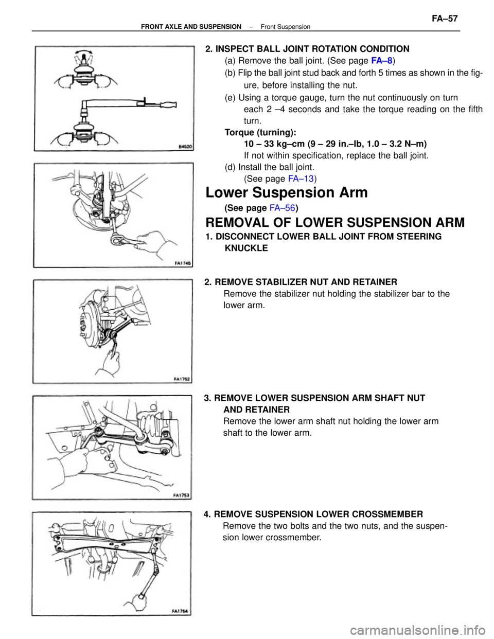
2. INSPECT BALL JOINT ROTATION CONDITION
(a) Remove the ball joint. (See page FA ± 8)
(b) Flip the ball joint stud back and forth 5 times as shown in the fig-
ure, before installing the nut.
(e) Using a torque gauge, turn the nut continuously on turn
each 2 ±4 seconds and take the torque reading on the fifth
turn.
Torque (turning):
10 ± 33 kg±cm (9 ± 29 in.±Ib, 1.0 ± 3.2 N±m)
If not within specification, replace the ball joint.
(d) Install the ball joint.
(See page FA±13)
Lower Suspension Arm
(See page FA±56)
REMOVAL OF LOWER SUSPENSION ARM
1. DISCONNECT LOWER BALL JOINT FROM STEERING
KNUCKLE
3. REMOVE LOWER SUSPENSION ARM SHAFT NUT
AND RETAINER
Remove the lower arm shaft nut holding the lower arm
shaft to the lower arm.
4. REMOVE SUSPENSION LOWER CROSSMEMBER
Remove the two bolts and the two nuts, and the suspen-
sion lower crossmember. 2. REMOVE STABILIZER NUT AND RETAINER
Remove the stabilizer nut holding the stabilizer bar to the
lower arm.
± FRONT AXLE AND SUSPENSIONFront SuspensionFA±57
Page 1425 of 2389
![TOYOTA CAMRY V20 1986 Service Information To Ignition SW
IG Terminal
Fuse
Relay
SW2 SolenoidVoltmeter [A]
[B]
[C] SW1
Ohmmeter
SW
INTRODUCTION±HOW TO PERFORM FOR SYSTEM INSPECTION
A±5
6
Wire Harness Repair Manual (RM1022E)
HOW TO PERFORM FO TOYOTA CAMRY V20 1986 Service Information To Ignition SW
IG Terminal
Fuse
Relay
SW2 SolenoidVoltmeter [A]
[B]
[C] SW1
Ohmmeter
SW
INTRODUCTION±HOW TO PERFORM FOR SYSTEM INSPECTION
A±5
6
Wire Harness Repair Manual (RM1022E)
HOW TO PERFORM FO](/manual-img/14/57449/w960_57449-1424.png)
To Ignition SW
IG Terminal
Fuse
Relay
SW2 SolenoidVoltmeter [A]
[B]
[C] SW1
Ohmmeter
SW
INTRODUCTION±HOW TO PERFORM FOR SYSTEM INSPECTION
A±5
6
Wire Harness Repair Manual (RM1022E)
HOW TO PERFORM FOR SYSTEM INSPECTION
This inspection procedure is a simple troubleshooting which should be carried out on the vehicle during
system operation and is based on the assumption of system component trouble
Always inspect the trouble taking the following items into consideration:
�Ground point fault
�Open or short circuit of the wire harness
�Connector or terminal connection fault
�Fuse or fusible link fault
NOTICE:
�This is an on±vehicle inspection during system operation.
Therefore, inspect the trouble with due regard for safety.
�If connecting the battery directly, be careful not to cause a short circuit, and select the applicable
voltage.
1. Voltage Check
(a)Establish conditions in which voltage is present at the
check point.
Example:
[A] ± Ignition SW on
[B] ± Ignition SW and SW 1 on
[C] ± Ignition SW, SW 1 and Relay on (SW 2 off)
(b)Using a voltmeter, connect the negative (±) lead to a
good ground point or negative (±) battery terminal
and the positive (+) lead to the connector or
component terminal. This check can be done with a
test bulb instead of a voltmeter.
2. Continuity and Resistance Check
(a)Disconnect the battery terminal or wire so there is no
voltage between the check points.
(b)Contact the two leads of an ohmmeter to each of the
check points.
A
Page 1427 of 2389
![TOYOTA CAMRY V20 1986 Service Information Fuse Case Test Bulb
Short [A]
SW1
Short [B]
Relay
Light
Short [C]
SW2 SolenoidDisconnect
Disconnect DisconnectTo Ignition SW
IG Terminal
INTRODUCTION±HOW TO PERFORM FOR SYSTEM INSPECTION
A±7
8
Wire TOYOTA CAMRY V20 1986 Service Information Fuse Case Test Bulb
Short [A]
SW1
Short [B]
Relay
Light
Short [C]
SW2 SolenoidDisconnect
Disconnect DisconnectTo Ignition SW
IG Terminal
INTRODUCTION±HOW TO PERFORM FOR SYSTEM INSPECTION
A±7
8
Wire](/manual-img/14/57449/w960_57449-1426.png)
Fuse Case Test Bulb
Short [A]
SW1
Short [B]
Relay
Light
Short [C]
SW2 SolenoidDisconnect
Disconnect DisconnectTo Ignition SW
IG Terminal
INTRODUCTION±HOW TO PERFORM FOR SYSTEM INSPECTION
A±7
8
Wire Harness Repair Manual (RM1022E)
4. Finding a Short Circuit
(a)Remove the blown fuse and eliminate all loads from
the fuse.
(b)Connect a test bulb in place of the fuse.
(c)Establish conditions in which the test bulb comes on.
Example:
[A] ± Ignition SW on
[B] ± Ignition SW and SW 1 on
[C] ± Ignition SW, SW 1 and Relay on (Connect the Relay)
and SW 2 off (or disconnect SW 2)
(d)Disconnect and reconnect the connectors while
watching the test bulb. The short lies between the
connector where the test bulb stays lit and the
connector where the bulb goes out.
(e)Find the exact location of the short by lightly shaking
the problem wire along the body.
CAUTION:
(a)Do not open the cover or the case of the ECU
unless absolutely necessary. (If the IC terminals
are touched, the IC may be destroyed by static
electricity.)
(b)When replacing the internal mechanism (ECU
part) of the digital meter, be careful that no part of
your body or clothing comes in contact with the
terminals of leads from the IC, etc. of the
replacement part (spare part).
A
Page 1447 of 2389

Notch Retainer
(Yellow)
Seal rubber
Condition of cover opening
Side Lock
Center Lock Side Lock
TERMINAL AND CONNECTOR REPAIR±TERMINAL REPLACEMENT
B±18
28
Wire Harness Repair Manual (RM1022E)
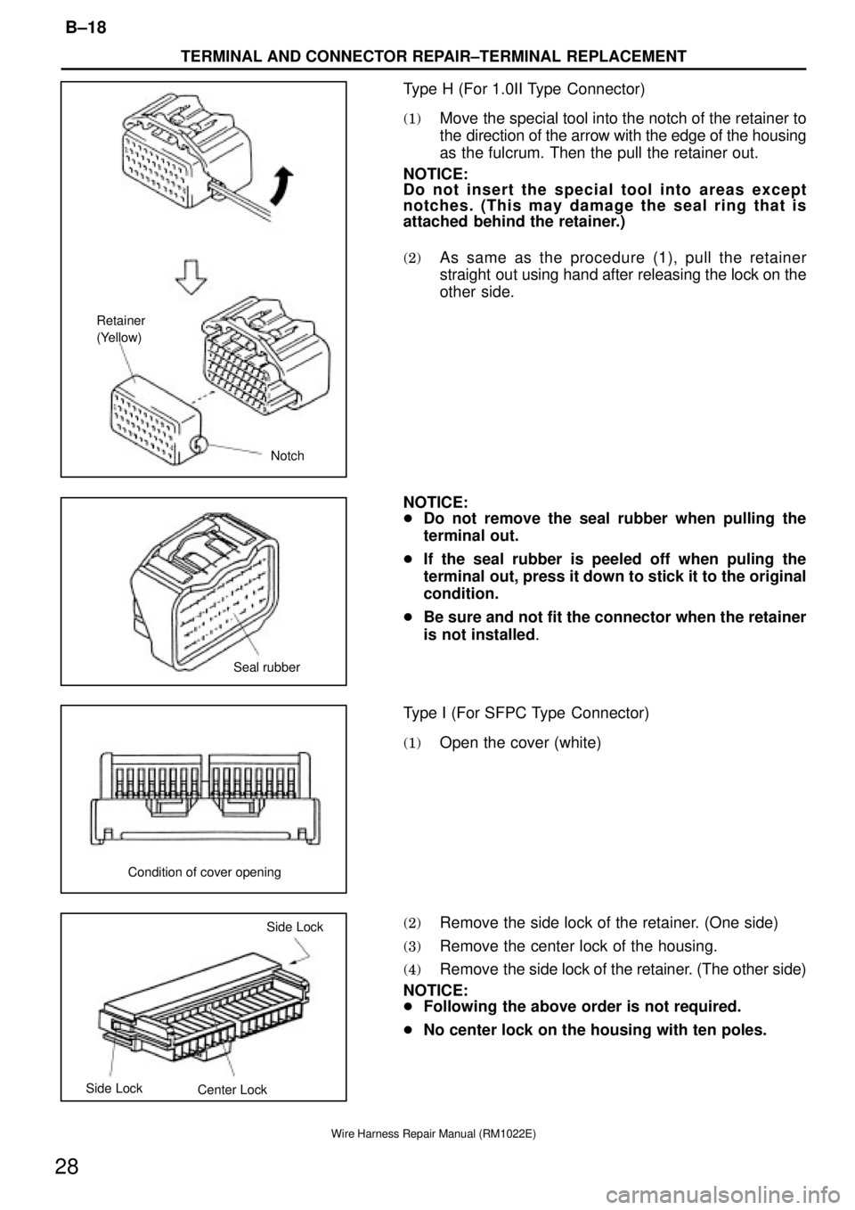
Type H (For 1.0II Type Connector)
(1)Move the special tool into the notch of the retainer to
the direction of the arrow with the edge of the housing
as the fulcrum. Then the pull the retainer out.
NOTICE:
Do not insert the special tool into areas except
notches. (This may damage the seal ring that is
attached behind the retainer.)
(2)As same as the procedure (1), pull the retainer
straight out using hand after releasing the lock on the
other side.
NOTICE:
�Do not remove the seal rubber when pulling the
terminal out.
�If the seal rubber is peeled off when puling the
terminal out, press it down to stick it to the original
condition.
�Be sure and not fit the connector when the retainer
is not installed.
Type I (For SFPC Type Connector)
(1)Open the cover (white)
(2)Remove the side lock of the retainer. (One side)
(3)Remove the center lock of the housing.
(4)Remove the side lock of the retainer. (The other side)
NOTICE:
�Following the above order is not required.
�No center lock on the housing with ten poles.
Page 1448 of 2389
Initial condition Retainer
Rubber Plug
Outer
Lock
Inner
Rubber Plug
A
Illustration from side BB OuterSpecial tool
Inner
B±19
TERMINAL AND CONNECTOR REPAIR±TERMINAL REPLACEMENT
29
Wire Harness Repair Manual (RM1022E)
(5)Move the retainer until it becomes the initial condition.
Type J
[Male]
(1)Remove the rubber plug.
(2)Push the lock of the inner using the special tool.
(3)Pull the wire to the direction of the arrow pushing the
lock up and remove the inner from the outer.
[Female]
(1)Remove the rubber plug.
(2)Insert the special tool into the outer shown in the
illustration. Then push the area A of the inner and
remove the inner from the outer.
Page 1461 of 2389

Special ToolLocking clip
Special Tool Terminal Lance ºInsulation Displacement Connectorº
Terminal Lance º0.64 Typeº
Special Tool
TERMINAL AND CONNECTOR REPAIR±TERMINAL REPLACEMENT
B±32
42
Wire Harness Repair Manual (RM1022E)
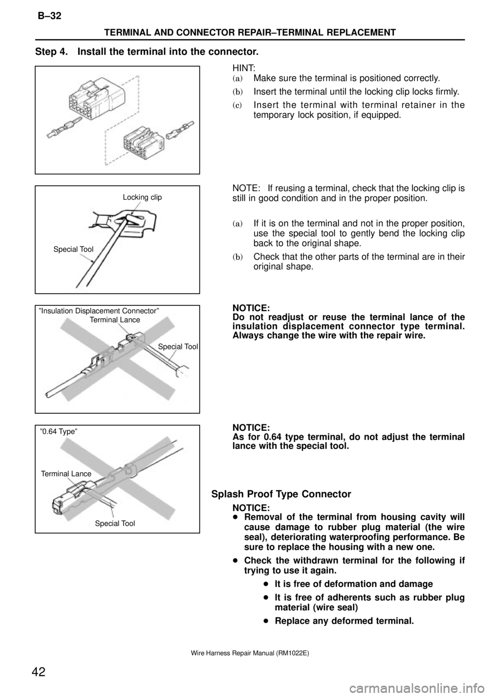
Step 4. Install the terminal into the connector.
HINT:
(a)Make sure the terminal is positioned correctly.
(b)Insert the terminal until the locking clip locks firmly.
(c)Insert the terminal with terminal retainer in the
temporary lock position, if equipped.
NOTE: If reusing a terminal, check that the locking clip is
still in good condition and in the proper position.
(a)If it is on the terminal and not in the proper position,
use the special tool to gently bend the locking clip
back to the original shape.
(b)Check that the other parts of the terminal are in their
original shape.
NOTICE:
Do not readjust or reuse the terminal lance of the
insulation displacement connector type terminal.
Always change the wire with the repair wire.
NOTICE:
As for 0.64 type terminal, do not adjust the terminal
lance with the special tool.
Splash Proof Type Connector
NOTICE:
�Removal of the terminal from housing cavity will
cause damage to rubber plug material (the wire
seal), deteriorating waterproofing performance. Be
sure to replace the housing with a new one.
�Check the withdrawn terminal for the following if
trying to use it again.
�It is free of deformation and damage
�It is free of adherents such as rubber plug
material (wire seal)
�Replace any deformed terminal.
Page 1476 of 2389
Lever
Lever
B±47
TERMINAL AND CONNECTOR REPAIR±HOW TO INSTALL AND REMOVE SPECIAL CONNECTORS
57
Wire Harness Repair Manual (RM1022E)
HOW TO INSTALL AND REMOVE SPECIAL CONNECTORS
Low Fit and Lever Type Connector
[Case 1]
1. Cut the connection of the connector
(1)Push the place indicated by the arrow.
(2)The lock is released and lever is lifted up.
(3)Lift the lever up until it stops.
an
(4)
Cut the connection of the connector.
NOTICE:
Do not hold the wire harness to pull it.
2. Connect the connector
(1)Connect the connector in the condition that the lever
is fully lifted up.
HINT: If the lever is locked at the lower position, follow
the procedure [Case 1]. (1) to (3) and lift the lever up fully.
Page 1478 of 2389
Lever
Lever is not locked
Lever
B±49
TERMINAL AND CONNECTOR REPAIR±HOW TO INSTALL AND REMOVE SPECIAL CONNECTORS
59
Wire Harness Repair Manual (RM1022E)
2. Connect the connector
(1)Connect the connector in the condition that the lever
is fully lifted up.
(2)Hold the connector to prevent it from slip off and push
it down until you hear a click to lock it.
(3)Confirm that the lever is securely locked.
[Case 3]
1. Cut the connection of the connector
(1)Pick the part indicated in the illustration by fingers.
(2)The lock is released and the lever is lifted up.
(3)Lift the lever up fully.