Page 1093 of 2389
INSPECTION OF COLD START
INJECTOR
1. INSPECT INJECTION OF COLD START INJECTOR
NOTICE: Keep clear for sparks during the test.
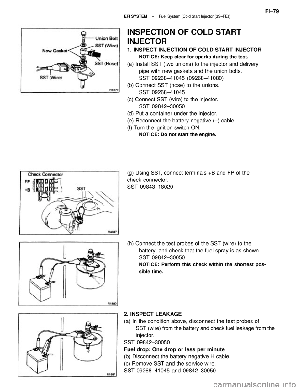
(a) Install SST (two unions) to the injector and delivery
pipe with new gaskets and the union bolts.
SST 09268±41045 (09268±41080)
(b) Connect SST (hose) to the unions.
SST 09268±41045
(c) Connect SST (wire) to the injector.
SST 09842±30050
(d) Put a container under the injector.
(e) Reconnect the battery negative (±) cable.
(f) Turn the ignition switch ON.
NOTICE: Do not start the engine.
2. INSPECT LEAKAGE
(a) In the condition above, disconnect the test probes of
SST (wire) from the battery and check fuel leakage from the
injector.
SST 09842±30050
Fuel drop: One drop or less per minute
(b) Disconnect the battery negative H cable.
(c) Remove SST and the service wire.
SST 09268±41045 and 09842±30050(h) Connect the test probes of the SST (wire) to the
battery, and check that the fuel spray is as shown.
SST 09842±30050
NOTICE: Perform this check within the shortest pos-
sible time.
(g) Using SST, connect terminals +B and FP of the
check connector.
SST 09843±18020
± EFI SYSTEMFuel System (Cold Start Injector (3S±FE))FI±79
Page 1096 of 2389
INSPECTION OF COLD START
INJECTOR
1. INSPECT INJECTION OF COLD START INJECTOR
NOTICE: Keep clear for sparks during the test.
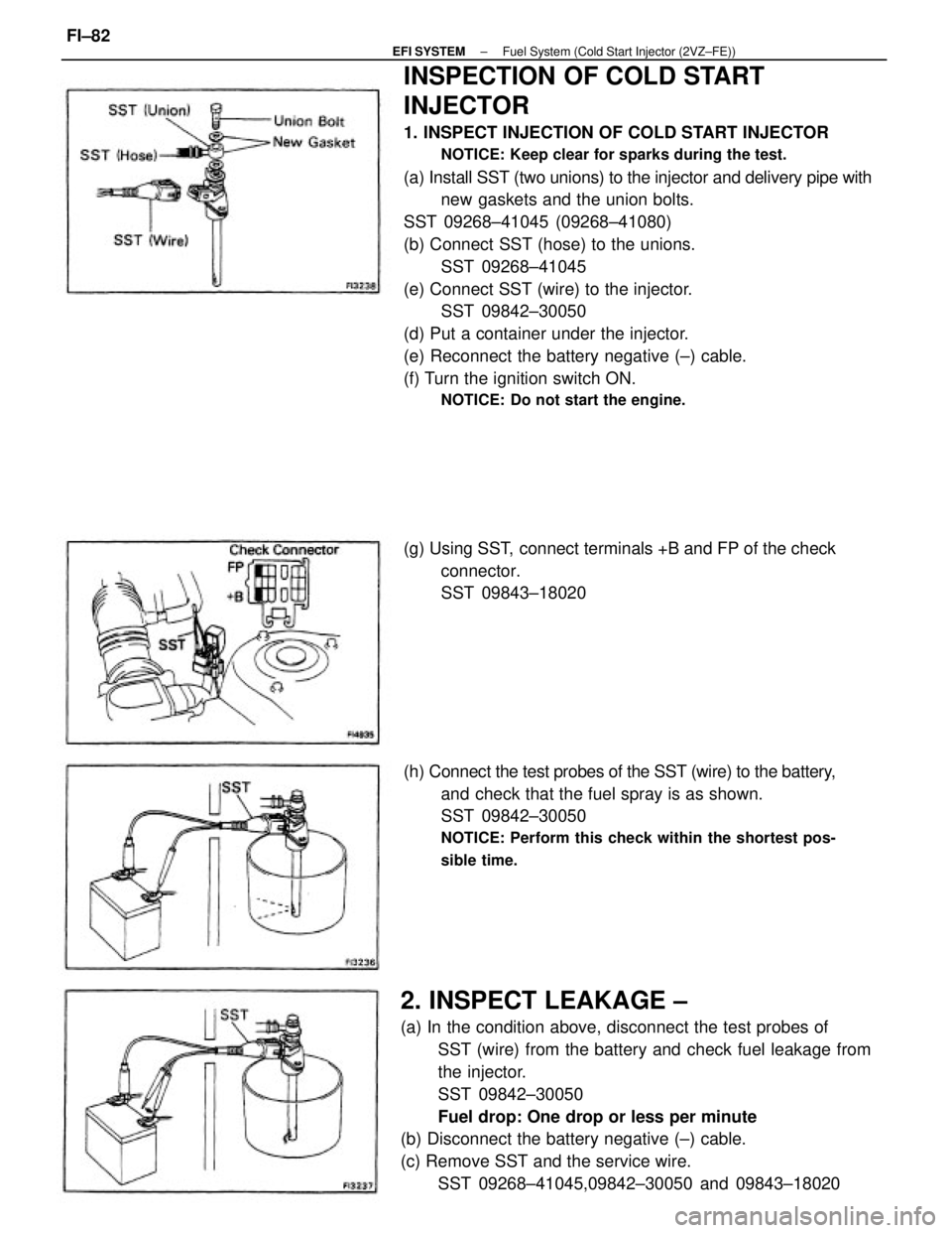
(a) Install SST (two unions) to the injector and delivery pipe with
new gaskets and the union bolts.
SST 09268±41045 (09268±41080)
(b) Connect SST (hose) to the unions.
SST 09268±41045
(e) Connect SST (wire) to the injector.
SST 09842±30050
(d) Put a container under the injector.
(e) Reconnect the battery negative (±) cable.
(f) Turn the ignition switch ON.
NOTICE: Do not start the engine.
2. INSPECT LEAKAGE ±
(a) In the condition above, disconnect the test probes of
SST (wire) from the battery and check fuel leakage from
the injector.
SST 09842±30050
Fuel drop: One drop or less per minute
(b) Disconnect the battery negative (±) cable.
(c) Remove SST and the service wire.
SST 09268±41045,09842±30050 and 09843±18020 (h) Connect the test probes of the SST (wire) to the battery,
and check that the fuel spray is as shown.
SST 09842±30050
NOTICE: Perform this check within the shortest pos-
sible time.
(g) Using SST, connect terminals +B and FP of the check
connector.
SST 09843±18020
± EFI SYSTEMFuel System (Cold Start Injector (2VZ±FE))FI±82
Page 1104 of 2389
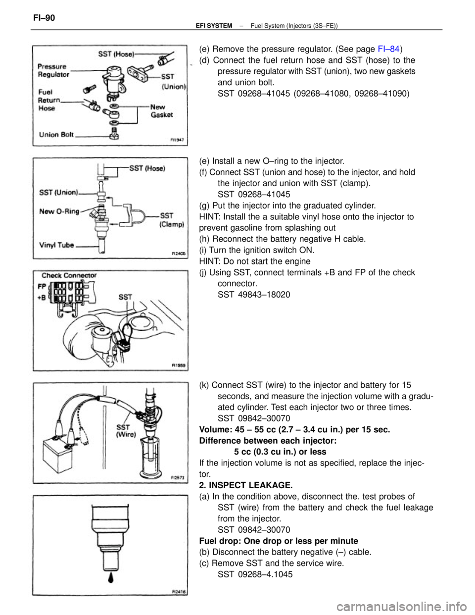
(k) Connect SST (wire) to the injector and battery for 15
seconds, and measure the injection volume with a gradu-
ated cylinder. Test each injector two or three times.
SST 09842±30070
Volume: 45 ± 55 cc (2.7 ± 3.4 cu in.) per 15 sec.
Difference between each injector:
5 cc (0.3 cu in.) or less
If the injection volume is not as specified, replace the injec-
tor.
2. INSPECT LEAKAGE.
(a) In the condition above, disconnect the. test probes of
SST (wire) from the battery and check the fuel leakage
from the injector.
SST 09842±30070
Fuel drop: One drop or less per minute
(b) Disconnect the battery negative (±) cable.
(c) Remove SST and the service wire.
SST 09268±4.1045 (e) Install a new O±ring to the injector.
(f) Connect SST (union and hose) to the injector, and hold
the injector and union with SST (clamp).
SST 09268±41045
(g) Put the injector into the graduated cylinder.
HINT: Install the a suitable vinyl hose onto the injector to
prevent gasoline from splashing out
(h) Reconnect the battery negative H cable.
(i) Turn the ignition switch ON.
HINT: Do not start the engine
(j) Using SST, connect terminals +B and FP of the check
connector.
SST 49843±18020 (e) Remove the pressure regulator. (See page FI±84)
(d) Connect the fuel return hose and SST (hose) to the
pressure regulator with SST (union), two new gaskets
and union bolt.
SST 09268±41045 (09268±41080, 09268±41090)
± EFI SYSTEMFuel System (Injectors (3S±FE))FI±90
Page 1111 of 2389
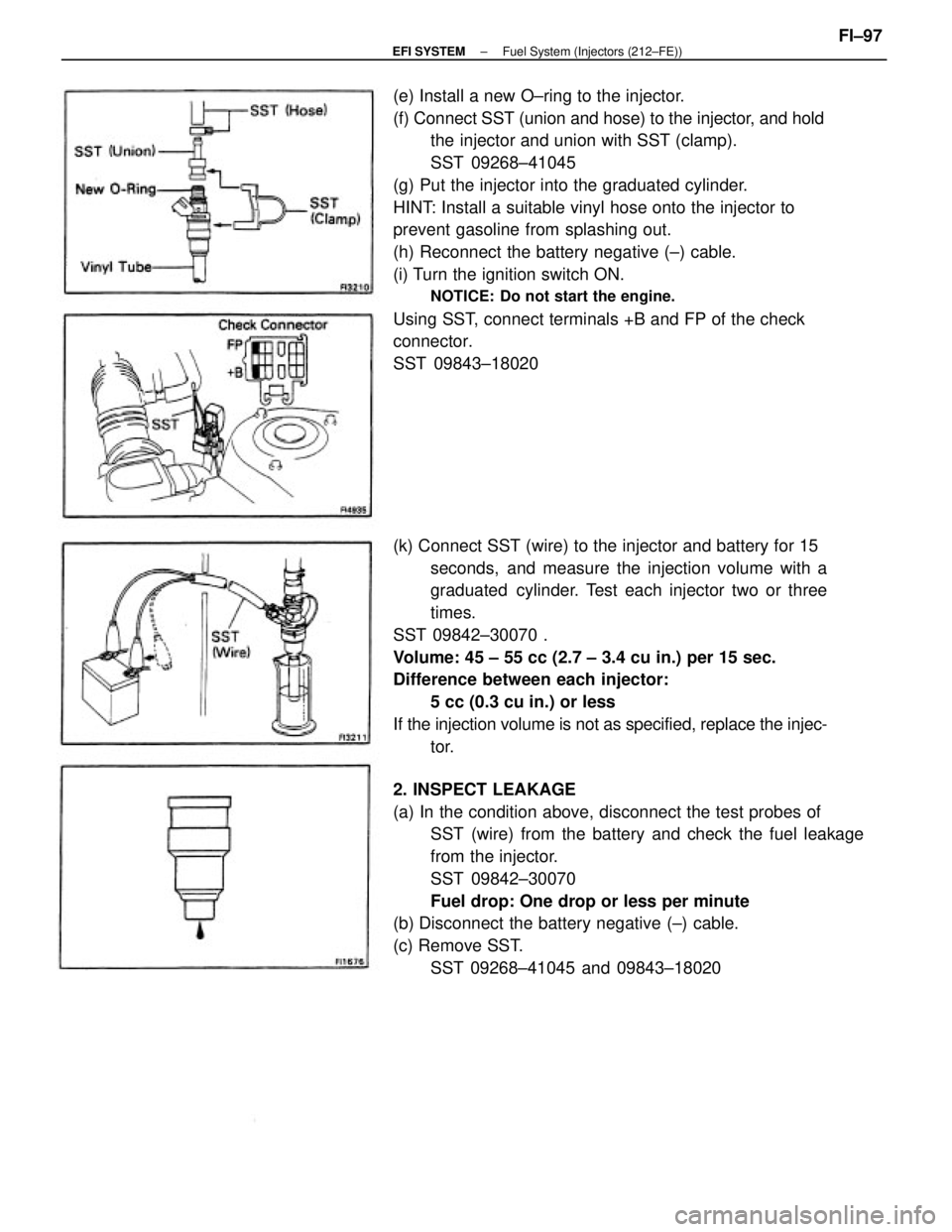
(e) Install a new O±ring to the injector.
(f) Connect SST (union and hose) to the injector, and hold
the injector and union with SST (clamp).
SST 09268±41045
(g) Put the injector into the graduated cylinder.
HINT: Install a suitable vinyl hose onto the injector to
prevent gasoline from splashing out.
(h) Reconnect the battery negative (±) cable.
(i) Turn the ignition switch ON.
NOTICE: Do not start the engine.
Using SST, connect terminals +B and FP of the check
connector.
SST 09843±18020
2. INSPECT LEAKAGE
(a) In the condition above, disconnect the test probes of
SST (wire) from the battery and check the fuel leakage
from the injector.
SST 09842±30070
Fuel drop: One drop or less per minute
(b) Disconnect the battery negative (±) cable.
(c) Remove SST.
SST 09268±41045 and 09843±18020 (k) Connect SST (wire) to the injector and battery for 15
seconds, and measure the injection volume with a
graduated cylinder. Test each injector two or three
times.
SST 09842±30070 .
Volume: 45 ± 55 cc (2.7 ± 3.4 cu in.) per 15 sec.
Difference between each injector:
5 cc (0.3 cu in.) or less
If the injection volume is not as specified, replace the injec-
tor.
± EFI SYSTEMFuel System (Injectors (212±FE))FI±97
Page 1130 of 2389
(b) Using SST, connect terminals TE1 and E1 of the check
connector.
SST 09843±18020
(c) After engine rpm are kept at 1,000 ± 1,300 rpm for 5
seconds, check that they return to idle speed.
If the rpm operation is not as specified, check the ISC
valve, wiring and ECU.
(d) Remove the service wire.
2. INSPECT ISC VALVE RESISTANCE
(a) Disconnect the ISC valve connector.
(b) Using an ohmmeter, measure the resistance between termi-
nal +B and other terminals (ISC1, ISC2).
Resistance: 16.0 ± 17.0
�
If the resistance is not as specified, replace the ISC valve.
(c) Reconnect the ISC valve connector.
ON±VEHICLE INSPECTION
1. INSPECT ISC VALVE OPERATION
(a) Initial conditions:
wEngine at normal operating temperature
wIdle speed set correctly
wTransmission in ºNº range
Idle Speed Control (ISC) Valve
(3S±FE)
± EFI SYSTEMAir Induction System (Idle Speed Control (ISC) Valve (3S±FE)FI±116
Page 1145 of 2389
Sub±Oxygen Sensor (CALIF. only)
INSPECTION OF SUB±OXYGEN
SENSOR
INSPECT SUB±OXYGEN SENSOR
HINT: Inspect only when code No.27 is displayed.
(a) Diagnostic code cancellation.
(See page FI±24)
(b) Warm up the engine until it reaches normal operating
temperature.
(a) (M/T)
Drive for 5 minutes or more between 80 km/h (50
mph) and 100 km/h in 4th or 5th gear.
(A/T)
Drive for 5 minutes or more between 80 km/h (50
mph) and 100 km/h (62 mph) in ºDº range.
(d) Following the conditions in step (e), press fully on the
accelerator pedal for 2 seconds or more.
HINT: Do not exceed 100 km/h (62 mph), or diagnostic code
will be cancelled.
(e) Stop the vehicle and turn the ignition switch to OFF.
(f) Carry out steps (b), (c) and (d) again to test acceleration.
If code No. 27 reappears again, check the sub±oxygen sensor
circuit. If the circuit is normal, replace the suboxygen sen-
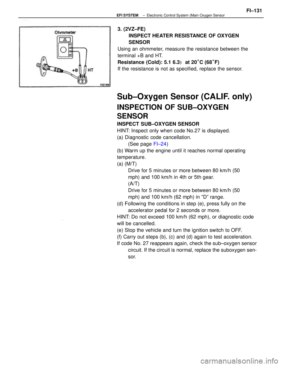
sor. 3. (2VZ±FE)
INSPECT HEATER RESISTANCE OF OXYGEN
SENSOR
Using an ohmmeter, measure the resistance between the
terminal +B and HT.
Resistance (Cold): 5.1 6.3� at 20°C (68°F)
If the resistance is not as specified, replace the sensor.
± EFI SYSTEMElectronic Control System (Main Oxygen SensorFI±131
Page 1146 of 2389
Sub±Oxygen Sensor (CALIF. only)
INSPECTION OF SUB±OXYGEN
SENSOR
INSPECT SUB±OXYGEN SENSOR
HINT: Inspect only when code No.27 is displayed.
(a) Diagnostic code cancellation.
(See page FI±24)
(b) Warm up the engine until it reaches normal operating
temperature.
(a) (M/T)
Drive for 5 minutes or more between 80 km/h (50
mph) and 100 km/h in 4th or 5th gear.
(A/T)
Drive for 5 minutes or more between 80 km/h (50
mph) and 100 km/h (62 mph) in ºDº range.
(d) Following the conditions in step (e), press fully on the
accelerator pedal for 2 seconds or more.
HINT: Do not exceed 100 km/h (62 mph), or diagnostic code
will be cancelled.
(e) Stop the vehicle and turn the ignition switch to OFF.
(f) Carry out steps (b), (c) and (d) again to test acceleration.
If code No. 27 reappears again, check the sub±oxygen sensor
circuit. If the circuit is normal, replace the suboxygen sen-
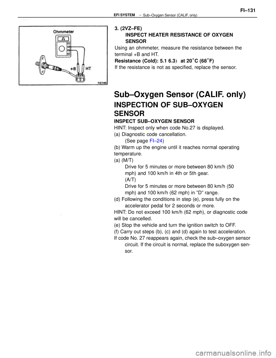
sor. 3. (2VZ±FE)
INSPECT HEATER RESISTANCE OF OXYGEN
SENSOR
Using an ohmmeter, measure the resistance between the
terminal +B and HT.
Resistance (Cold): 5.1 6.3� at 20°C (68°F)
If the resistance is not as specified, replace the sensor.
± EFI SYSTEM
Sub±Oxygen Sensor (CALIF. only)FI±131
Page 1148 of 2389
Voltage at ECU Wiring Connectors (3S±FE)
No trouble (ºCHECKº engine warning light off) and engine running
Stop light SW 4N (Brake pedal depressed) or defogger SW ONCheck connector TE1 ± E1 not connected
Check connector TE 1 ± E 1 connectedMeasuring plate fully closed
Ex. shift position P or N rangeIntake air temp. 20°C (68°F)
Coolant temp. 80°C (1 760F) Measuring plate fully open
Shift position P or N rangeThrottle valve fully closedThrottle valve fully closed
Heater blower SW ON Air conditioning ONThrottle valve open
Throttle valve open
Throttle valve open
Cranking or idlingIG SW ONSTD voltage (V) Condition
3,000 rpm
IG SW ONIG SW ON1G SW ON
IG SW ON Terminals
IG SW ON
CrankingIdling
± EFI SYSTEMElectronic Control System (Electronic Controlled Unit(ECU))
FI±133