Page 963 of 2389
1. INSPECT RELAY CONTINUITY
(a) Using an ohmmeter, check that there is continuity between
terminals 1 and 3.
(b) Check that there is continuity between terminals 2 and
4.
(c) Check that there is no continuity between terminals 4
and 5.
If continuity is not as specified, replace the relay.
2. INSPECT RELAY OPERATION
(a) Apply battery voltage across terminals 1 and 3.
(b) Using an ohmmeter, check that there is continuity between
terminals 4 and 5.
(e) Check that there is no continuity between terminals 2
and 4.
If operation is not as specified, replace the relay.
ENGINE MAIN RELAY
INSPECTION OF ENGINE MAIN RELAY
LOCATION:
3S±FE In the relay box in the engine compartment.
2VZ±FE On the LH fender apron rear side in the engine
compartment.
± CHARGING SYSTEMEngine Main RelayCH±16
Page 964 of 2389
REMOVAL OF ALTERNATOR (3S±FE)
1. DISCONNECT CABLE FROM NEGATIVE TERMINAL
OF BATTERY
2. DISCONNECT CONNECTOR AND WIRE FROM
ALTERNATOR
3. REMOVE DRIVE BELT
4. REMOVE ALTERNATOR
Remove the adjusting lock bolt, pivot bolt and alternator.
ALTERNATOR
COMPONENTS
± CHARGING SYSTEMAlternatorCH±6
Page 965 of 2389
REMOVAL OF ALTERNATOR (2VZ±FE)
1. DISCONNECT CABLE FROM NEGATIVE TERMINAL
OF BATTERY
2. REMOVE NO. 2 RH MOUNTING STAY
3. DISCONNECT CONNECTOR AND WIRE FROM
ALTERNATOR
4. DISCONNECT WIRE HARNESS FROM CLIP
5. REMOVE DRIVE BELT
6. REMOVE ALTERNATOR
Remove the adjusting lock bolt, pivot bolt and alternator.
DISASSEMBLY OF ALTERNATOR
(See page CH±6)
1. REMOVE REAR END COVER
(a) Remove the nut and terminal insulator.
(b) Remove the three nuts and end cover.
3. REMOVE RECTIFIER HOLDER
(a) Remove the four screws and rectifier holder.
(b) Remove the four rubber insulators.2. REMOVE BRUSH HOLDER AND IC REGULATOR
Remove the five screws, brush holder and IC regulator.
± CHARGING SYSTEMAlternatorCH±7
Page 972 of 2389
2. INSTALL DRIVE BELT
Adjust the drive belt tension. (See step 3 on page CH±3)
Drive belt tension:
w/ A/C New belt 175 + 5 lb
Used belt 130+ 10 lb
w/o A/C New belt 125 t 25 Ib
Used belt 95 + 20 Ib
3. CONNECT CONNECTOR AND WIRE TO ALTERNATOR
4. CONNECT CABLE TO NEGATIVE TERMINAL OF
BATTERY
5. PERFORM ON±VEHICLE INSPECTION
(See steps 5 to 7 on pages CH±4 and 5)
INSTALLATION OF ALTERNATOR
(3S±FE)
1. INSTALL ALTERNATOR
Mount the alternator on the alternator brackets with the
pivot bolt and adjusting lock bolt. Do not tighten the bolts
yet. 6. INSTALL REAR END COVER
(a) Install the end cover with the three nuts.
(b) Install the terminal insulator with the nut.
7. CHECK THAT ROTOR ROTATES SMOOTHLY
± CHARGING SYSTEMAlternatorCH±14
Page 973 of 2389
2. INSTALL DRIVE BELT
Adjust the drive belt tension. (See step 3 on page CH±3)
Drive belt tension:
New belt 175 ± 5 Ib
Used belt 115
+ 20 Ib
3. CONNECT CONNECTOR AND WIRE TO ALTERNATOR
4. CONNECT WIRE HARNESS TO CLIP
5. INSTALL NO.2 RH MOUNT STAY
Torque: Bolt 890 kg±cm (64 ft±Ib, 87 N±m)
Nut 530 kg±cm (38 ft±Ib, 52 N±m)
6. CONNECT CABLE TO NEGATIVE TERMINAL OF
BATTERY
7. PERFORM ON±VEHICLE INSPECTION
(See steps 5 to 7 on pages CH±4 and 5)
INSTALLATION OF ALTERNATOR
(2VA±FE)
1. INSTALL ALTERNATOR
Mount the alternator on the alternator bracket with the pivot
bolt and adjusting lock bolt. Do not tighten the bolts yet.
± CHARGING SYSTEMAlternatorCH±15
Page 1003 of 2389

REMOVAL OF RADIATO
1. DRAIN ENGINE COOLANT (See page CO±4 or 5)
2. REMOVE BATTERY
3. REMOVE IGNITION COIL (2VZ±FE), IGNITER AND
BRACKET ASSEMBLY
4. DISCONNECT COOLANT RESERVOIR HOSE
5. DISCONNECT RADIATOR NOSE
6. DISCONNECT COOLING FAN MOTOR
CONNECTOR(S)
7. (A/T)
DISCONNECT OIL COOLER HOSES
8. REMOVE RADIATOR AND ELECTRIC COOLING
FAN(S)
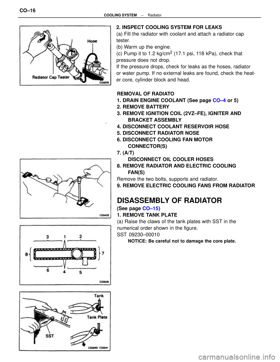
Remove the two bolts, supports and radiator.
9. REMOVE ELECTRIC COOLING FANS FROM RADIATOR
DISASSEMBLY OF RADIATOR
(See page CO±15)
1. REMOVE TANK PLATE
(a) Raise the claws of the tank plates with SST in the
numerical order shown in the figure.
SST 09230±00010
NOTICE: Be careful not to damage the core plate.
2. INSPECT COOLING SYSTEM FOR LEAKS
(a) Fill the radiator with coolant and attach a radiator cap
tester.
(b) Warm up the engine.
(c) Pump it to 1.2 kg/cm
2 (17.1 psi, 118 kPa), check that
pressure does not drop.
If the pressure drops, check for leaks as the hoses, radiator
or water pump. If no external leaks are found, check the heat-
er core, cylinder block and head.
± COOLING SYSTEMRadiatorCO±16
Page 1007 of 2389

INSTALLATION OF RADIATOR
1. INSTALL ELECTRIC COOLING FANS TO RADIATOR
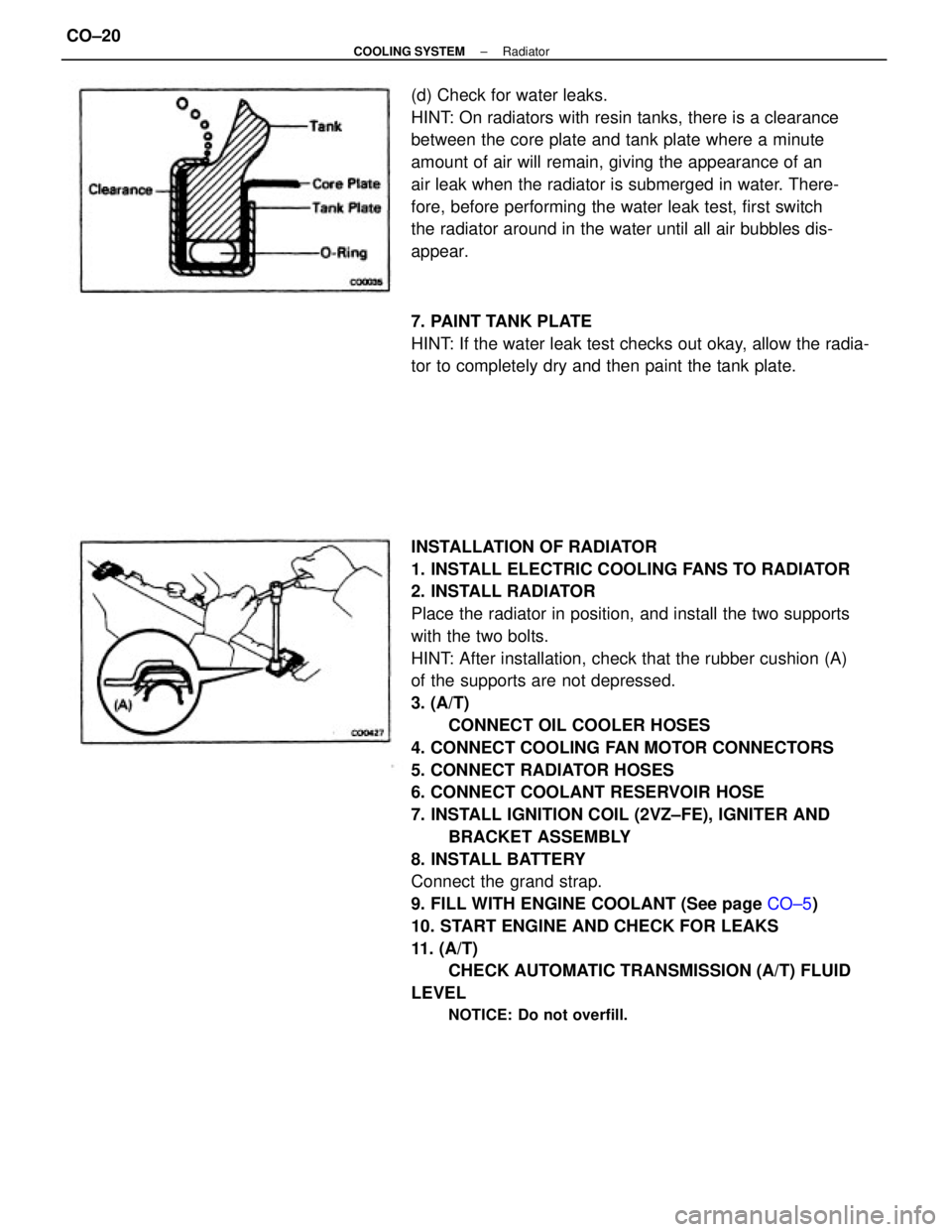
2. INSTALL RADIATOR
Place the radiator in position, and install the two supports
with the two bolts.
HINT: After installation, check that the rubber cushion (A)
of the supports are not depressed.
3. (A/T)
CONNECT OIL COOLER HOSES
4. CONNECT COOLING FAN MOTOR CONNECTORS
5. CONNECT RADIATOR HOSES
6. CONNECT COOLANT RESERVOIR HOSE
7. INSTALL IGNITION COIL (2VZ±FE), IGNITER AND
BRACKET ASSEMBLY
8. INSTALL BATTERY
Connect the grand strap.
9. FILL WITH ENGINE COOLANT (See page CO±5)
10. START ENGINE AND CHECK FOR LEAKS
11. (A/T)
CHECK AUTOMATIC TRANSMISSION (A/T) FLUID
LEVEL
NOTICE: Do not overfill.
(d) Check for water leaks.
HINT: On radiators with resin tanks, there is a clearance
between the core plate and tank plate where a minute
amount of air will remain, giving the appearance of an
air leak when the radiator is submerged in water. There-
fore, before performing the water leak test, first switch
the radiator around in the water until all air bubbles dis-
appear.
7. PAINT TANK PLATE
HINT: If the water leak test checks out okay, allow the radia-
tor to completely dry and then paint the tank plate.
± COOLING SYSTEMRadiatorCO±20
Page 1009 of 2389

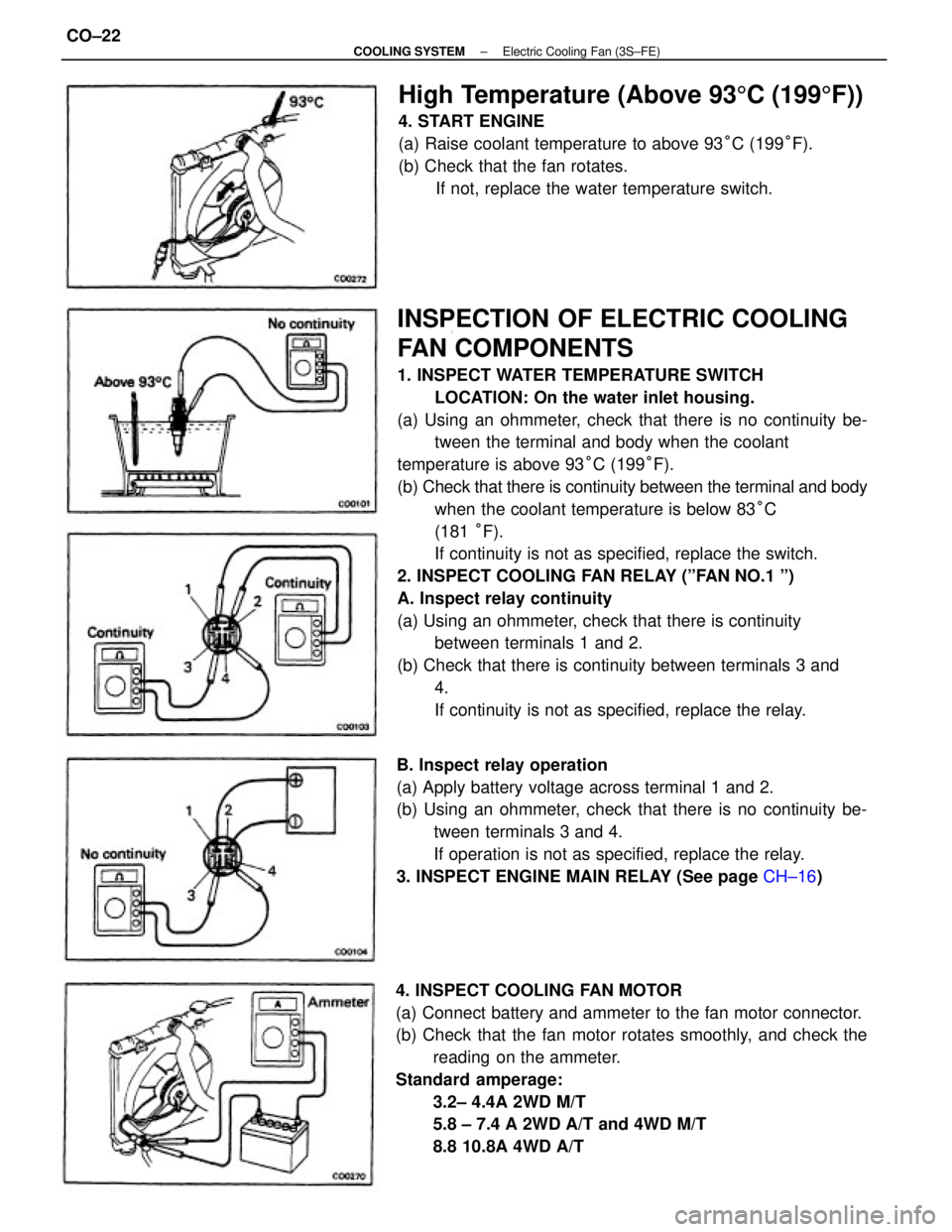
INSPECTION OF ELECTRIC COOLING
FAN COMPONENTS
1. INSPECT WATER TEMPERATURE SWITCH
LOCATION: On the water inlet housing.
(a) Using an ohmmeter, check that there is no continuity be-
tween the terminal and body when the coolant
temperature is above 93°C (199°F).
(b) Check that there is continuity between the terminal and body
when the coolant temperature is below 83°C
(181 °F).
If continuity is not as specified, replace the switch.
2. INSPECT COOLING FAN RELAY (ºFAN NO.1 º)
A. Inspect relay continuity
(a) Using an ohmmeter, check that there is continuity
between terminals 1 and 2.
(b) Check that there is continuity between terminals 3 and
4.
If continuity is not as specified, replace the relay.
4. INSPECT COOLING FAN MOTOR
(a) Connect battery and ammeter to the fan motor connector.
(b) Check that the fan motor rotates smoothly, and check the
reading on the ammeter.
Standard amperage:
3.2± 4.4A 2WD M/T
5.8 ± 7.4 A 2WD A/T and 4WD M/T
8.8 10.8A 4WD A/T B. Inspect relay operation
(a) Apply battery voltage across terminal 1 and 2.
(b) Using an ohmmeter, check that there is no continuity be-
tween terminals 3 and 4.
If operation is not as specified, replace the relay.
3. INSPECT ENGINE MAIN RELAY (See page CH±16)
High Temperature (Above 935C (1995F))
4. START ENGINE
(a) Raise coolant temperature to above 93°C (199°F).
(b) Check that the fan rotates.
If not, replace the water temperature switch.
± COOLING SYSTEMElectric Cooling Fan (3S±FE)CO±22