Page 446 of 513

ENGINE
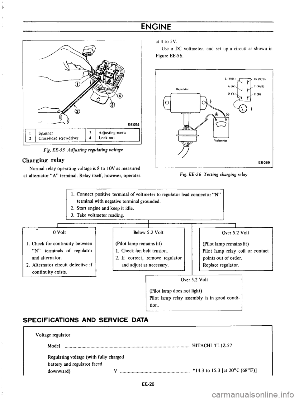
at
4
to
5
V
Use
i
f
DC
voltmeter
and
set
up
a
circuit
as
shown
in
Figure
EE
56
EEQ58
L
W
R
IG
Will
r
AI
W
lli
r
N
Y
vge
I
JJ
Rtl
ublOr
I
I
Spanner
Cross
head
screwdriver
I
I
Adjusting
screw
Lock
nut
Vollm
lcl
Fig
EE
55
Adjusting
Tegulating
voltage
Charging
relay
Normal
relay
operating
voltage
is
8
to
10V
as
measured
at
alternator
A
terminal
Relay
itself
however
operates
EE059
Fig
EE
56
Testing
chaTging
Telay
Connect
positive
terminal
of
voltmeter
to
regulator
lead
connector
N
terminal
with
negative
terminal
grounded
2
Start
engine
and
keep
it
idle
3
Take
voltmeter
reading
o
Volt
Below
5
2
Volt
I
Over
5
2
Volt
I
Check
for
continuity
between
N
terminals
of
regulator
and
alternator
2
Alternator
circuit
defective
if
continuity
exists
pilot
lamp
remains
lit
I
Check
fan
belt
tension
2
If
correct
remove
regulator
and
adjust
as
necessary
Pilot
lamp
remains
lit
Pilot
lamp
relay
coil
or
contact
points
out
of
order
Replace
regulator
Over
5
2
Volt
Pilot
lamp
does
not
light
Pilot
lamp
relay
assembly
is
in
good
condi
tion
SPECIFICATIONS
AND
SERVICE
DATA
Voltage
regulator
Model
HITACHI
TLl
Z
57
Regulating
voltage
with
fully
charged
battery
and
regulator
faced
downward
V
14
3
to
15
3
at
200C
680F
EE
26
Page 457 of 513

ENGINE
ElECTRICAL
SYSTEM
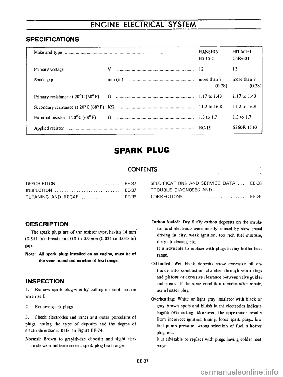
SPECIFICATIONS
Make
and
type
Primary
voltage
v
Spark
gap
mm
in
Primary
resistance
at
200C
680
F
n
Secondary
resistance
at
200C
680F
Kn
External
resistor
at
200C
680
F
n
Applied
resistor
HANSHIN
HITACHI
H5
15
2
C6R
601
12
12
more
than
7
more
than
7
0
28
0
28
1
17
to
I
43
l
l
7
to
I
43
11
2
to
16
8
11
2
to
16
8
l
3tol7
l
3tol7
RC
15
5560R
151O
SPARK
PLUG
CONTENTS
DESCRIPTION
INSPECTION
CLEANING
AND
REGAP
EE
37
EE
37
EE
38
DESCRIPTION
The
spark
plugs
are
of
the
resister
type
having
14
mm
0
551
in
threads
and
0
8
to
0
9
mm
0
031
to
0
Q35
in
gap
Note
All
spark
plugs
installed
on
an
engine
must
be
of
the
same
brand
and
number
of
heat
range
INSPECTION
1
Remove
spark
plug
wire
by
pulling
on
boot
not
on
wire
itself
2
Remove
spark
plugs
3
Check
electrodes
and
inner
and
outer
porcelains
of
plugs
noting
the
type
of
deposits
and
the
degree
of
electrode
erosion
Refer
to
Figure
EE
74
Normal
Brown
to
grayish
tan
deposits
and
slight
elec
trode
wear
indicate
correct
spark
plug
heat
range
SPECIFICATIONS
AND
SERVICE
DATA
TROUBLE
DIAGNOSES
AND
CORRECTIONS
EE
38
EE
39
Carbon
fouled
Dry
fluffy
carbon
deposits
on
the
insula
tor
and
electrode
were
mostly
caused
by
slow
speed
driving
in
city
weak
ignition
too
rich
fuel
mixture
dirty
air
cleaner
etc
H
is
advisable
to
replace
with
plugs
having
hotter
heat
range
Oil
fouled
Wet
black
deposits
show
excessive
oil
en
trance
into
combustion
chamber
through
worn
rings
and
pistons
or
excessive
clearance
between
valve
guides
and
stems
If
the
same
condition
remains
after
repair
use
a
hotter
plug
Overheating
White
or
light
gray
insulator
with
black
or
gray
brown
spots
and
bluish
burnt
electrodes
indicate
engine
overheating
Moreover
the
appearance
results
from
incorrect
ignition
timing
loose
spark
plugs
low
fuel
pump
pressure
wrong
selection
of
fuel
a
hotter
plug
etc
H
is
advisable
to
replace
with
plugs
having
colder
heat
range
EE
37
Page 483 of 513

CLUTCH
Operating
cylinder
clutch
Operating
cylinder
diameter
T
Ilhtening
torque
19
05
mm
0
750
in
Clutch
assembly
securing
bolt
1
5
to
2
2
kg
m
10
8
to
15
9
ft
Ib
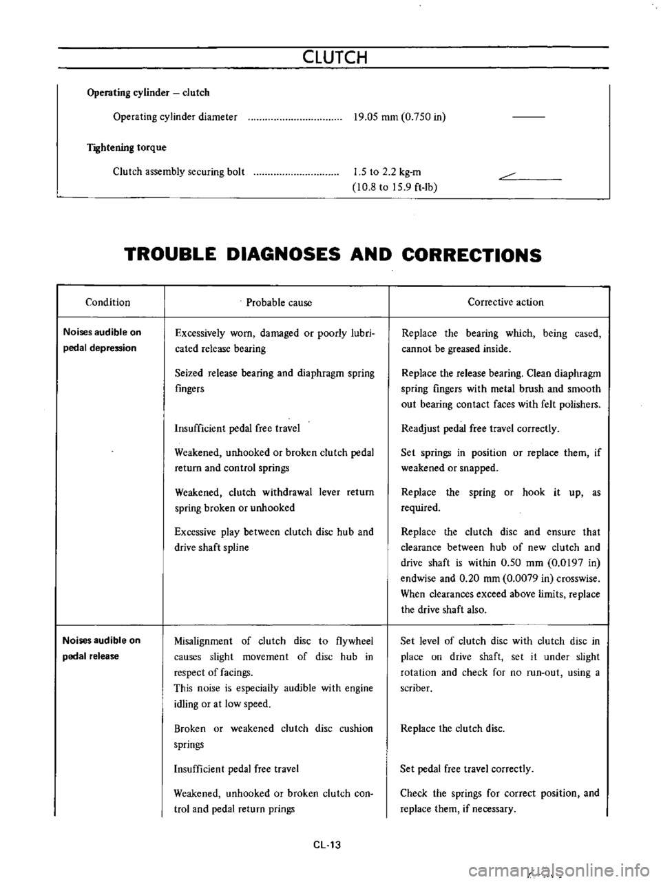
TROUBLE
DIAGNOSES
AND
CORRECTIONS
Condition
Noises
audible
on
pedal
depression
Noises
audible
on
pedal
release
Probable
cause
Excessively
worn
damaged
or
poorly
lubri
cated
release
bearing
Seized
release
bearing
and
diaphragm
spring
fingers
Insufficient
pedal
free
travel
Weakened
unhooked
or
broken
clutch
pedal
return
and
control
springs
Weakened
clutch
withdrawal
lever
return
spring
broken
or
unhooked
Excessive
play
between
clutch
disc
hub
and
drive
shaft
spline
Misalignment
of
clutch
disc
to
flywheel
causes
slight
movement
of
disc
hub
in
respect
of
facings
This
noise
is
especially
audible
with
engine
idling
or
at
low
speed
Broken
or
weakened
clutch
disc
cushion
springs
Insufficient
pedal
free
travel
Weakened
unhooked
or
broken
clutch
con
trol
and
pedal
return
prings
CL
13
Corrective
action
Replace
the
bearing
which
being
cased
cannot
be
greased
inside
Replace
the
release
bearing
Clean
diaphragm
spring
fingers
with
metal
brush
and
smooth
out
bearing
contact
faces
with
felt
polishers
Readjust
pedal
free
travel
correctly
Set
springs
in
position
or
replace
them
if
weakened
or
snapped
Replace
the
spring
or
hook
it
up
as
required
Replace
the
clutch
disc
and
ensure
that
clearance
between
hub
of
new
clutch
and
drive
shaft
is
within
0
50
mm
0
0197
in
endwise
and
0
20
mm
0
0079
in
crosswise
When
clearances
exceed
above
limits
replace
the
drive
shaft
also
Set
level
of
clutch
disc
with
clutch
disc
in
place
on
drive
shaft
set
it
under
slight
rotation
and
check
for
no
run
out
using
a
scriber
Replace
the
clutch
disc
Set
pedal
free
travel
correctly
Check
the
springs
for
correct
position
and
replace
them
if
necessary
Page:
< prev 1-8 9-16 17-24