1973 DATSUN B110 check engine light
[x] Cancel search: check engine lightPage 311 of 513

ENGINE
4
Install
a
timing
light
on
No
cylinder
spark
plug
wire
and
install
a
tachometer
5
Set
idling
speed
to
approximately
800
rpm
6
Check
ignition
timing
if
it
is
50BTDC
Before
Top
of
Dead
Center
by
the
use
of
timing
light
If
necessary
adjust
it
as
follows
Loosen
set
screw
to
such
an
extent
that
distributor
can
be
moved
by
hand
2
Adjust
ignition
timing
to
50BTDC
3
Lock
distributor
set
screw
and
make
sure
that
timing
is
correct
Fig
ET
9
Checking
ignition
timing
Ignition
timing
degree
50
B
T
D
C
Checking
or
replacing
distributor
breaker
point
condenser
and
spark
plugs
Distributor
breaker
point
Check
distributot
breaker
points
for
abnormal
pitting
and
wear
Replace
if
necessary
Make
sure
they
are
in
correct
alignment
for
full
contact
and
that
point
dwell
and
gap
are
correct
Clean
and
apply
distributor
grease
to
earn
and
wick
Note
Do
not
apply
grease
excessively
Distributor
Point
gap
0
45
to
0
55
mm
0
018
to
0
Q22
in
49
to
55
degrees
Dwell
angle
ET004
Fig
ET
10
Checking
distributor
point
gap
Condenser
I
Clean
outlet
of
condenser
lead
wire
and
check
for
loose
set
screw
Retighten
if
necessary
2
Check
condenser
capacity
with
a
capacity
meter
Condenser
insulation
resistance
may
be
also
checked
using
a
tester
by
adjusting
its
range
to
measure
large
resistance
value
When
condenser
is
normal
the
tester
pointer
swings
largely
and
rapidly
and
moves
gradually
back
to
the
infmite
side
When
the
pointet
does
not
stay
still
or
it
points
zero
in
resistance
replacement
is
necessary
Condenser
capacity
0
221LF
Micro
Farad
Condenser
insulation
resistance
5
Mn
Mega
ohms
Spark
plugs
Remove
and
clean
plugs
in
a
sand
blast
cleaner
Inspect
each
spark
plug
Make
sure
that
they
are
of
the
specified
heat
tange
Inspect
insulator
for
cracks
and
chips
Check
both
center
and
ground
electrodes
If
they
are
excessi
ely
worn
replace
with
new
spark
plugs
File
center
electrode
flat
Set
the
gap
to
0
8
to
0
9
rom
0
031
to
0
035
in
using
the
proper
adjusting
tool
Tighten
plugs
to
1
5
to
2
0
kg
m
11
0
to
15
0
ft
lb
torque
ET
6
Page 314 of 513

EMISSION
CONTROL
AND
TUNE
UP
Checking
and
adjusting
dash
pot
automatic
transmission
model
only
Check
operation
of
dash
pot
It
should
not
be
cracked
or
bound
It
is
also
essential
to
check
to
be
certain
that
it
is
in
correct
adjustment
L
Check
to
be
sure
that
dash
pot
contacts
stopper
lever
when
engine
speed
reaches
1
900
to
2
000
rpm
2
Engine
should
be
slowed
down
from
3
000
to
1
000
rpm
within
a
few
seconds
Readjust
dash
pot
or
replace
it
with
a
new
one
if
it
fails
to
meet
the
above
conditions
Checking
carburetor
return
spring
Check
throttle
return
spring
for
sign
of
damage
wear
or
squareness
Discard
spring
if
found
with
any
of
above
excessively
beyond
use
Checking
choke
mechanism
choke
valve
and
linkage
1
Check
choke
valve
and
mechanism
for
free
operation
and
clean
or
replace
if
necessary
A
binding
condition
may
have
developed
from
petro
leum
gum
for
motion
on
choke
shaft
or
from
damage
2
Check
bimetal
cover
setting
position
The
index
mark
of
bimetal
cover
is
usually
aligned
at
the
middle
point
of
the
scale
Note
When
somewhat
over
choked
turn
bimetal
caver
clockwise
slightly
3
Prior
to
starting
check
to
be
sure
that
choke
valve
closes
automatically
when
pressing
down
on
accelerator
pedal
Should
it
fail
to
close
automatically
the
likelihood
is
that
fast
idle
cam
is
out
of
proper
adjustment
or
that
bimetal
is
not
properly
adjusted
calling
for
adjustment
Refer
to
Carburetor
in
Section
EF
Page
EF
15
Checking
anti
dieseling
solenoid
If
engine
will
not
stop
when
ignition
switch
is
turned
off
this
indicates
a
striking
closed
solenoid
valve
shutting
off
supply
of
fuel
to
engine
If
harness
is
in
good
condition
replace
solenoid
as
a
unit
To
replace
proceed
as
follows
Removal
and
installation
of
anti
dieseling
solenoid
Removal
Solenoid
is
cemented
at
factory
Use
special
tool
STl
91
50000
to
remove
a
solenoid
When
this
tool
is
not
effective
use
a
pair
of
pliers
to
loosen
body
out
of
position
lnstalltion
I
Before
installing
a
solenoid
it
is
essential
to
clean
all
threaded
parts
of
carburetor
and
solenoid
Supply
screws
in
holes
and
turn
them
in
two
or
three
pitches
2
First
without
disturbing
the
above
setting
coat
all
exposed
threads
with
adhensive
the
Stud
Lock
of
LOCTlTE
or
equivalent
Then
torque
screws
to
35
to
55
kg
cm
30
to
48
in
lb
using
a
special
tool
STl9150000
After
installing
anti
dieseling
solenoid
leave
the
carbu
retor
more
than
12
hours
without
operation
3
After
replacement
is
over
start
engine
and
check
to
be
sure
that
fuel
is
not
leaking
and
that
anti
dieseling
solenoid
is
in
good
condition
Notes
a
Do
not
allow
adhesive
getting
on
valve
Failure
to
follow
this
caution
would
result
in
improper
valve
performance
or
clogged
fuel
passage
b
I
n
installing
valve
use
caution
not
to
hold
body
directly
Instead
use
special
tool
tighten
ing
nuts
as
required
ET
9
Page 315 of 513
ENGINE
Replacing
fuel
filter
Check
for
a
contamination
element
water
deposit
and
defection
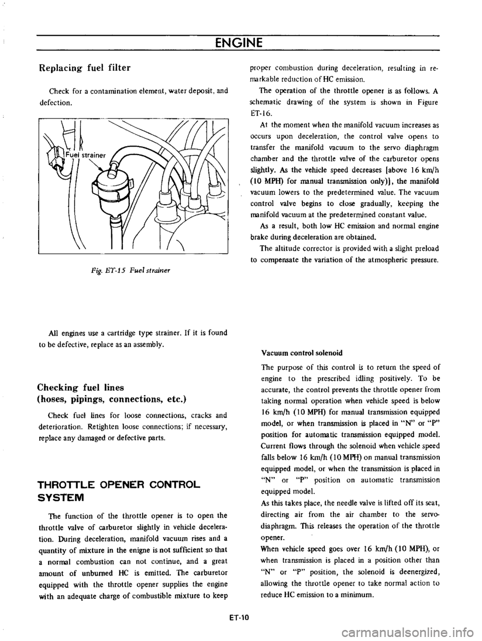
Fig
ET
15
Fuel
strcrineT
All
engines
use
a
cartridge
type
strainer
If
it
is
found
to
be
defective
replace
as
an
assembly
Checking
fuel
lines
hoses
pipings
connections
etc
Check
fuel
lines
for
loose
connections
cracks
and
deterioration
Retighten
loose
connections
if
necessary
replace
any
damaged
or
defective
parts
THROTTLE
OPENER
CONTROL
SYSTEM
The
function
of
the
throttle
opener
is
to
open
the
throttle
valve
of
carburetor
slightly
in
vehicle
decelera
tion
During
deceleration
manifold
vacuum
rises
and
a
quantity
of
mixture
in
the
enigne
is
not
sufficient
so
that
a
normal
combustion
can
not
continue
and
a
great
amount
of
unburned
HC
is
emitted
The
carburetor
equipped
with
the
throttle
opener
supplies
the
engine
with
an
adequate
charge
of
combustible
mixture
to
keep
proper
combustion
during
deceleration
resulting
in
re
markable
reduction
of
He
emission
The
operation
of
the
throttle
opener
is
as
follows
A
schematic
drawing
of
the
system
is
shown
in
Figure
ET
16
At
the
moment
when
the
manifold
vacuum
increases
as
occurs
upon
deceleration
the
control
valve
opens
to
transfer
the
manifold
vacuum
to
the
servo
diaphragm
chamber
and
the
throttle
valve
of
the
carburetor
opens
slightly
As
the
vehicle
speed
decreases
above
16
km
h
10
MPH
for
manual
transmission
only
the
manifold
vacuum
lowers
to
the
predetermined
value
The
vacuum
control
valve
begins
to
close
gradually
keeping
the
manifold
vacuum
at
the
predetermined
constant
value
As
a
result
both
low
HC
emission
and
normal
engine
brake
during
deceleration
are
obtained
The
altitude
corrector
is
provided
with
a
slight
preload
to
compensate
the
variation
of
the
atmospheric
pressure
Vacuum
control
solenoid
The
purpose
of
this
control
is
to
return
the
speed
of
engine
to
the
prescribed
idling
positively
To
be
accurate
the
control
prevents
the
throttle
opener
from
taking
normal
operation
when
vehicle
speed
is
below
16
km
h
IO
MPH
for
manual
transmission
equipped
model
or
when
transmission
is
placed
in
N
or
P
position
for
automatic
transmission
equipped
model
Current
flows
through
the
solenoid
when
vehicle
speed
falls
below
16
km
h
10
MPH
on
manual
transmission
equipped
model
or
when
the
transmission
is
placed
in
N
or
P
position
on
automatic
transmission
equipped
model
As
this
takes
place
the
needle
valve
is
lifted
off
its
seat
directing
air
from
the
air
chamber
to
the
servo
diaphragm
This
releases
the
operation
of
the
throttle
opener
When
vehicle
speed
goes
over
16
km
h
IO
MPH
or
when
transmission
is
placed
in
a
position
other
than
N
or
P
position
the
solenoid
is
deenergized
allowing
the
throttle
opener
to
take
normal
action
to
reduce
He
emission
to
a
minimum
ET
10
Page 329 of 513
ENGINE
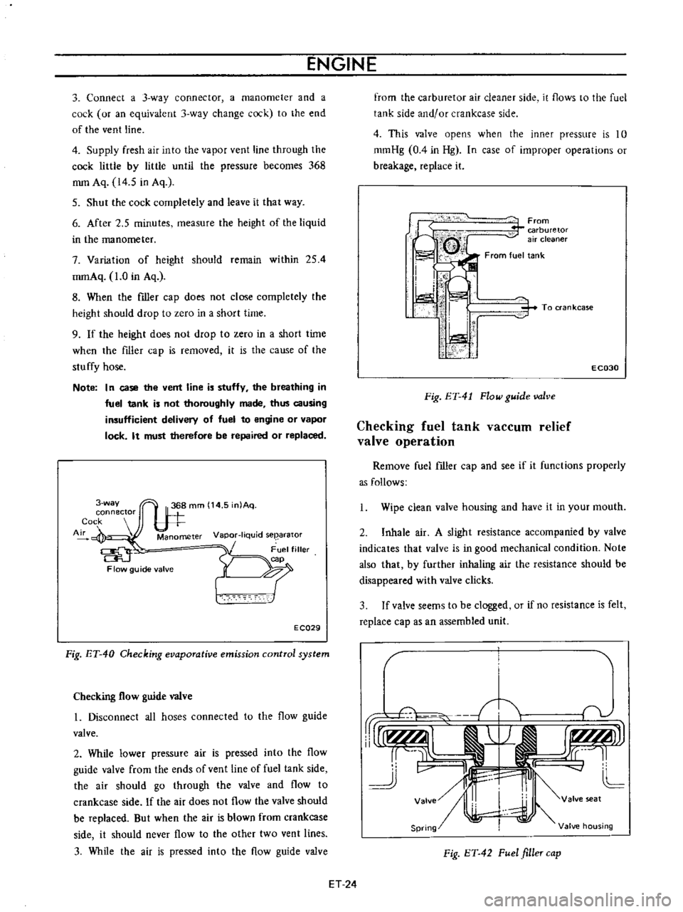
3
Connect
a
3
way
connector
a
manometer
and
a
cock
or
an
equivalent
3
way
change
cock
to
the
end
of
the
vent
line
4
Supply
fresh
air
into
the
vapor
vent
line
through
the
cock
little
by
little
until
the
pressure
becomes
368
mm
Aq
14
5
in
Aq
5
Shut
the
cock
completely
and
leave
it
that
way
6
After
2
5
minutes
measure
the
height
of
the
liquid
in
the
manometer
7
Variation
of
height
should
remain
within
254
mmAq
1
0
in
Aq
8
When
the
filler
cap
does
not
close
completely
the
height
should
drop
to
zero
in
a
short
time
9
If
the
height
does
not
drop
to
zero
in
a
short
time
when
the
filler
cap
is
removed
it
is
the
cause
of
the
stuffy
hose
Note
In
case
the
vent
line
is
stuffy
the
breathing
in
fuel
tank
is
not
thoroughly
made
thus
causing
insufficient
delivery
of
fuel
to
engine
or
vapor
lock
It
must
therefore
be
repaired
or
replaced
3
way
connector
Cock
Air
Manometer
Vapor
liquid
seearator
Flow
guide
valve
E
CQ29
Fig
ET
40
Checking
evaporative
emission
control
system
Checking
flow
guide
valve
I
Disconnect
all
hoses
connected
to
the
flow
guide
valve
2
While
lower
pressure
air
is
pressed
into
the
flow
guide
valve
from
the
ends
of
vent
line
of
fuel
tank
side
the
air
should
go
through
the
valve
and
flow
to
crankcase
side
If
the
air
does
not
flow
the
valve
should
be
replaced
But
when
the
air
is
blown
from
crankcase
side
it
should
never
flow
to
the
other
two
vent
lines
3
While
the
air
is
pressed
into
the
flow
guide
valve
from
the
carburetor
air
cleaner
side
it
flows
to
the
fuel
tank
side
and
or
crankcase
side
4
This
valve
opens
when
the
inner
pressure
is
10
mmHg
0
4
in
Hg
In
case
of
improper
operations
or
breakage
replace
it
From
carburetor
air
cleaner
From
fuel
tank
i
I
I
ti
i
i
1
1
i
To
ran
kcase
E
C030
Fig
ET
41
Flow
guide
valve
Checking
fuel
tank
vaCCUID
relief
valve
operation
Remove
fuel
filler
cap
and
see
if
it
functions
properly
as
follows
Wipe
clean
valve
housing
and
have
it
in
your
mouth
2
Inhale
air
A
slight
resistance
accompanied
by
valve
indicates
that
valve
is
in
good
mechanical
condition
Note
also
that
by
further
inhaling
air
the
resistance
should
be
disappeared
with
valve
clicks
3
If
valve
seems
to
be
clogged
or
if
no
resistance
is
felt
replace
cap
as
an
assembled
unit
T
1i
v
rUr1f
AlI
j
r
I
r
tLMJJl
rr
L
cc
11
J
v
II
4J
L
Valve
I
valve
seat
Spring
Valve
housing
Fig
ET
42
Fuel
filler
cap
ET
24
Page 332 of 513

EMISSION
CONTROL
AND
TUNE
UP
Trouble
shooting
procedure
on
starting
circuit
Switch
on
the
starting
motor
with
light
put
on
When
light
goes
off
or
dims
considerably
a
Check
battery
b
Check
cable
for
connection
c
Check
starter
motor
When
light
stays
bright
a
Check
wiring
connection
between
battery
and
starter
motor
b
Check
starter
switch
c
Check
starter
motor
ENGINE
WILL
CRANK
NORMALLY
BUT
WILL
NOT
START
In
this
case
following
trouble
causes
may
exist
In
the
most
causes
ignition
system
or
fuel
system
is
in
trouble
Ignition
system
in
trouble
Fuel
system
in
trouble
Valve
mechanism
does
not
work
properly
Low
compression
Check
spark
plug
first
in
accordance
with
the
following
procedure
Disconnect
high
tension
cable
from
one
spark
plug
and
hold
it
about
10
rom
0
4
in
away
from
the
engine
metal
part
and
crank
the
engine
Good
spark
occurs
a
Check
spark
plug
b
Check
ignition
timing
Check
fuel
system
d
Check
cylinder
compression
No
spark
occurs
Check
the
current
flow
in
primary
circuit
Very
high
current
Inspect
primary
circuit
for
short
Check
breaker
point
for
operation
Low
or
no
current
Check
for
loose
terminal
or
disconnection
in
primary
circuit
Check
for
burned
points
Ignition
system
in
trouble
Burned
distributor
point
Repair
or
replace
Improper
point
gap
Adjust
Defective
capacitor
Replace
Rotor
cap
and
rotor
leak
Replace
ET
27
ti
Page 336 of 513
EMISSION
CONTROL
AND
TUNE
UP
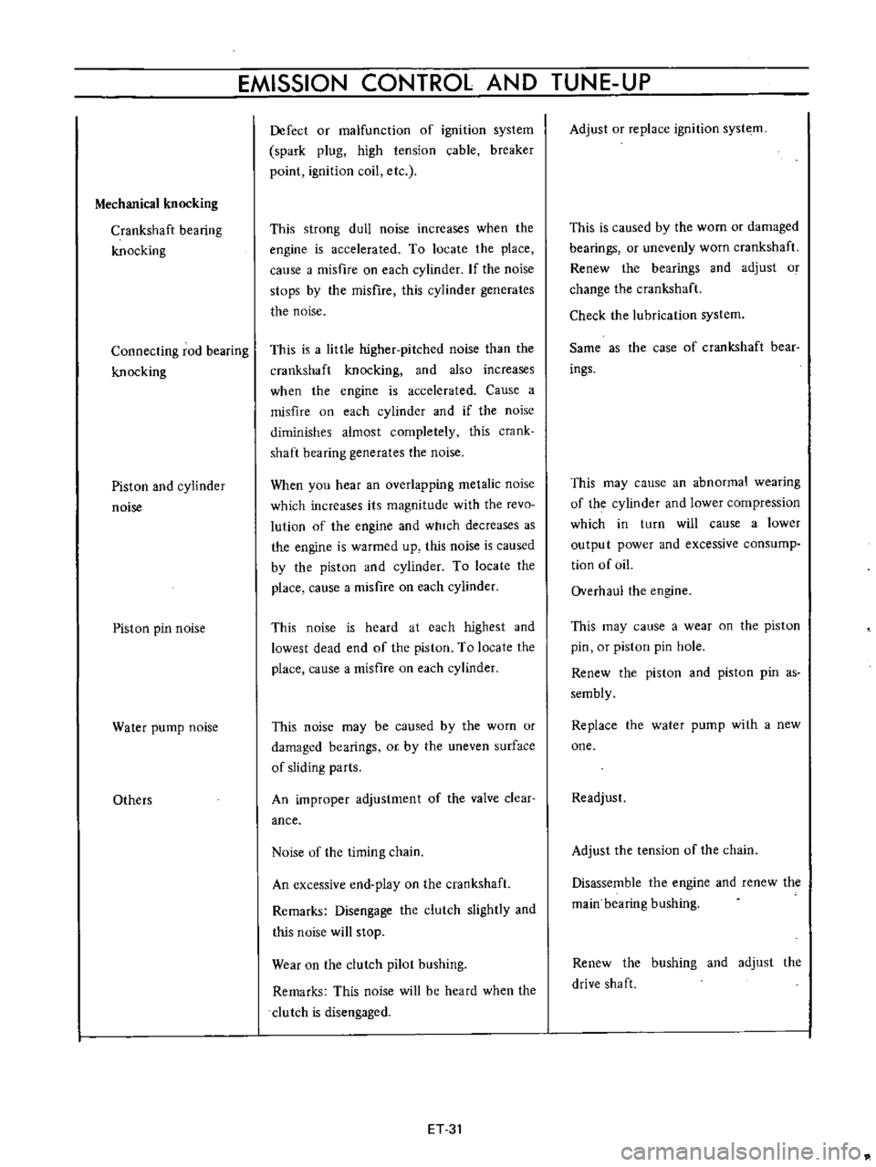
Mechanical
knocking
Crankshaft
bearing
knocking
Connecting
rod
bearing
knocking
Piston
and
cylinder
noise
Piston
pin
noise
Water
pump
noise
Others
Defect
or
malfunction
of
ignition
system
spark
plug
high
tension
cable
breaker
point
ignition
coil
etc
This
strong
dull
noise
increases
when
the
engine
is
accelerated
To
locate
the
place
calise
a
misfire
on
each
cylinder
If
the
noise
stops
by
the
misfire
this
cylinder
generates
the
noise
This
is
a
little
higher
pitched
noise
than
the
crankshaft
knocking
and
also
increases
when
the
engine
is
accelerated
Cause
a
misfire
on
each
cylinder
and
if
the
noise
diminishes
almost
completely
this
crank
shaft
bearing
generates
the
noise
When
you
hear
an
overlapping
metalic
noise
which
increases
its
magnitude
with
the
revo
lution
of
the
engine
and
which
decreases
as
the
engine
is
warmed
up
this
noise
is
caused
by
the
piston
and
cylinder
To
locate
the
place
cause
a
misfire
on
each
cylinder
This
noise
is
heard
at
each
highest
and
lowest
dead
end
of
the
piston
To
locate
the
place
cause
a
misfire
on
each
cylinder
This
noise
may
be
caused
by
the
worn
or
damaged
bearings
or
by
the
uneven
surface
of
sliding
parts
An
improper
adjustment
of
the
valve
clear
ance
Noise
of
the
timing
chain
An
excessive
end
play
on
the
crankshaft
Remarks
Disengage
the
clutch
slightly
and
this
noise
will
stop
Wear
on
the
clutch
pilot
bushing
Remarks
This
noise
will
be
heard
when
the
clutch
is
disengaged
ET
31
Adjust
or
replace
ignition
syste
m
This
is
caused
by
the
wom
or
damaged
bearings
or
unevenly
worn
crankshaft
Renew
the
bearings
and
adjust
o
change
the
crankshaft
Check
the
lubrication
system
Same
as
the
case
of
crankshaft
bear
ings
This
may
cause
an
abnormal
wearing
of
the
cylinder
and
lower
compression
which
in
turn
will
cause
a
lower
output
power
and
excessive
consump
tion
of
oiL
Overhaul
the
engine
This
may
cause
a
wear
on
the
piston
pin
or
piston
pin
hole
Renew
the
piston
and
piston
pin
as
sembly
Replace
the
water
pump
with
a
new
one
Readjust
Adjust
the
tension
of
the
chain
Disassemble
the
engine
and
renew
the
main
bearing
bushing
Renew
the
bushing
and
adjust
the
drive
shaft
Page 427 of 513
ENGINE
ElECTRICAL
SYSTEM
l
J
r
@
V
I
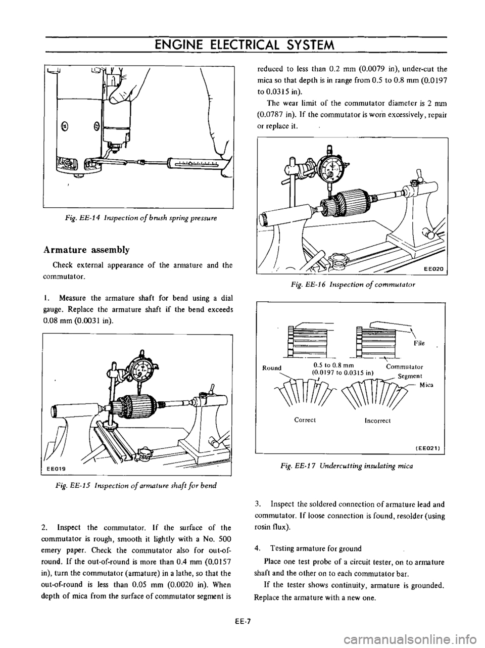
Fig
EE
14
Inspection
of
brush
spring
pressure
Armature
assembly
Check
external
appearance
of
the
armature
and
the
commutator
I
Measure
the
armature
shaft
for
bend
using
a
dial
gauge
Replace
the
armature
shaft
if
the
bend
exceeds
0
08
mm
0
0031
in
EE019
Fig
EE
15
Inspection
of
aTmatuTe
shaft
faT
bend
2
Inspect
the
commutator
If
the
surface
of
the
commutator
is
rough
smooth
it
lightly
with
a
No
500
emery
paper
Check
the
commutator
also
for
out
of
round
Ifthe
out
of
round
is
more
than
0
4
mm
0
0157
in
turn
the
commutator
armature
in
a
lathe
so
that
the
out
of
round
is
less
than
0
05
mm
0
0020
in
When
depth
of
mica
from
the
surface
of
commutator
segment
is
reduced
to
less
than
0
2
mm
0
0079
in
under
cut
the
mica
so
that
depth
is
in
range
from
0
5
to
0
8
mm
0
0197
to
0
0315
in
The
wear
limit
of
the
commutator
diameter
is
2
nun
0
0787
in
If
the
commutator
is
worn
excessively
repair
or
replace
it
Fig
EE
16
Inspection
of
commutator
f
L
I
C
9
File
4
J
Round
0
5
to
0
8
rom
Commutator
O
OI97tOO
0315m
S
t
egmen
1l1
Mica
Correct
Incorrect
EE021
Fig
EE
j
7
Undercutting
insulating
mica
3
Inspect
the
soldered
connection
of
armature
lead
and
commutator
If
loose
connection
is
found
resolder
using
rosin
flux
4
Testing
armature
for
ground
Place
one
test
probe
of
a
circuit
tester
on
to
arma
ture
shaft
and
the
other
on
to
each
commutator
bar
If
the
tester
shows
continuity
armature
is
grounded
Replace
the
armature
with
a
new
one
EE
7
Page 442 of 513
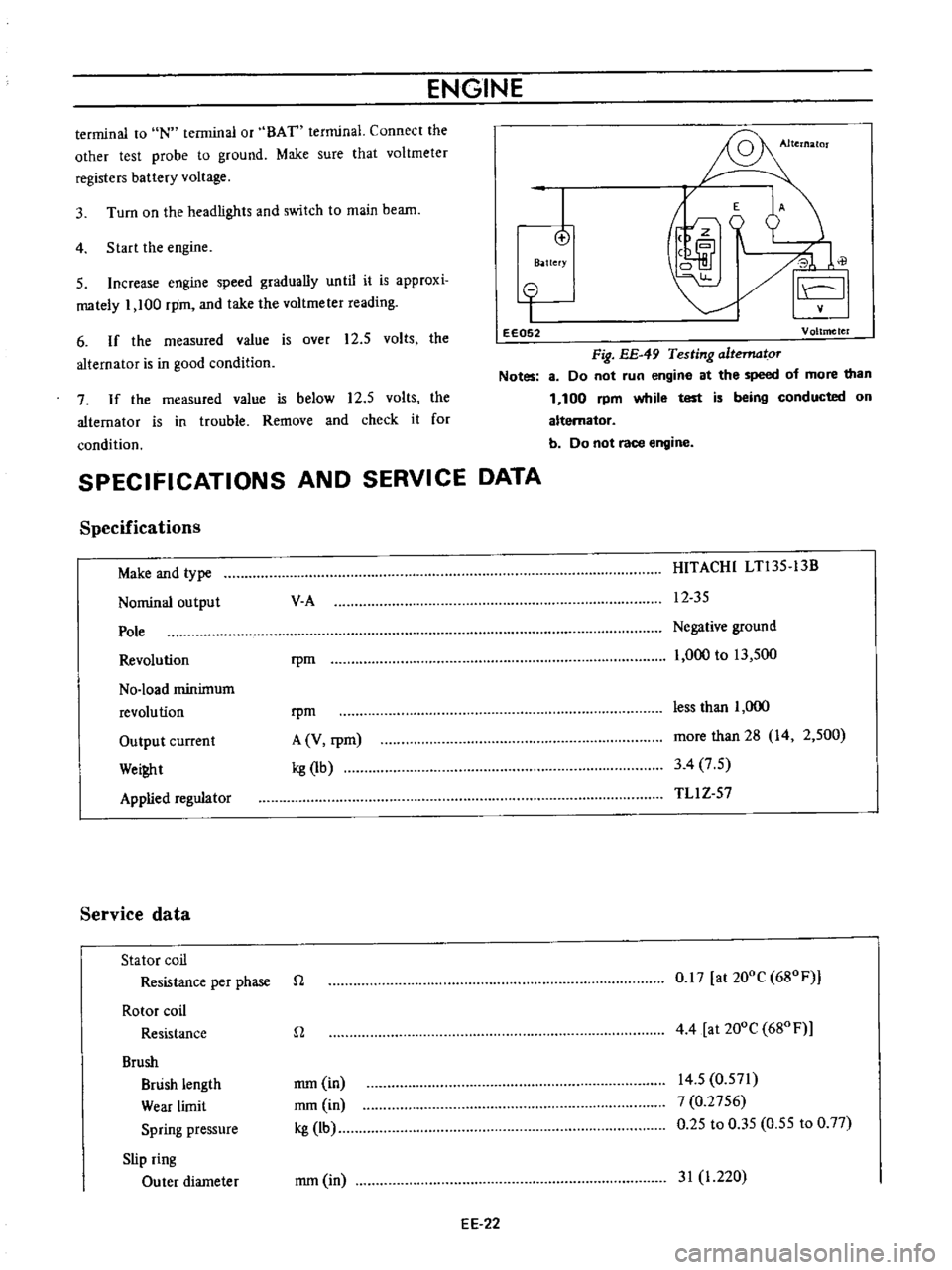
ENGINE
terminal
to
IN
terminal
or
BAT
terminal
Connect
the
other
test
probe
to
ground
Make
sure
that
voltmeter
registers
battery
voltage
4
Start
the
engine
3
Turn
on
the
headlights
and
switch
to
main
beam
I
o
B
ttefY
E
A
J
0
il
I
5
Increase
engine
speed
gradually
until
it
is
approxi
mately
1
100
rpm
and
take
the
voltmeter
reading
6
If
the
measured
value
is
over
12
5
volts
the
alternator
is
in
good
condition
o
I
eE052
Voltmeter
Fig
EE
49
Testing
altematoT
Notes
8
Do
not
run
engine
at
the
speed
of
more
than
1
100
rpm
while
test
is
being
conducted
on
alternator
b
Do
not
race
engine
7
If
the
measured
value
is
below
12
5
volts
the
alternator
is
in
trouble
Remove
and
check
it
for
condition
SPECIFICATIONS
AND
SERVICE
DATA
Specifications
Make
and
type
Nominal
output
Pole
Revolution
No
load
minimum
revolution
Output
current
Wei
t
Applied
regulator
Service
data
Stator
coil
Resistance
per
phase
Rotor
coil
Resistance
Brush
Brush
length
Wear
limit
Spring
pressure
Slip
ring
Outer
diameter
V
A
HITACHI
LTl35
13B
12
35
rpm
Negative
ground
1
000
to
13
500
rpm
A
V
rpm
kg
1b
less
than
1
000
more
than
28
14
2
500
3
4
7
5
TLl
Z
57
n
0
17
at
200C
680F
n
4
4
at
200e
680
F
mm
in
mm
in
kg
lb
14
5
0
571
7
0
2756
0
25
to
0
35
0
55
to
0
77
mm
in
31
1
220
EE
22