1973 DATSUN B110 belt
[x] Cancel search: beltPage 191 of 513
BODY
GENERAL
DESCRIPTION
CONTENTS
DESCRIPTION
BF
1
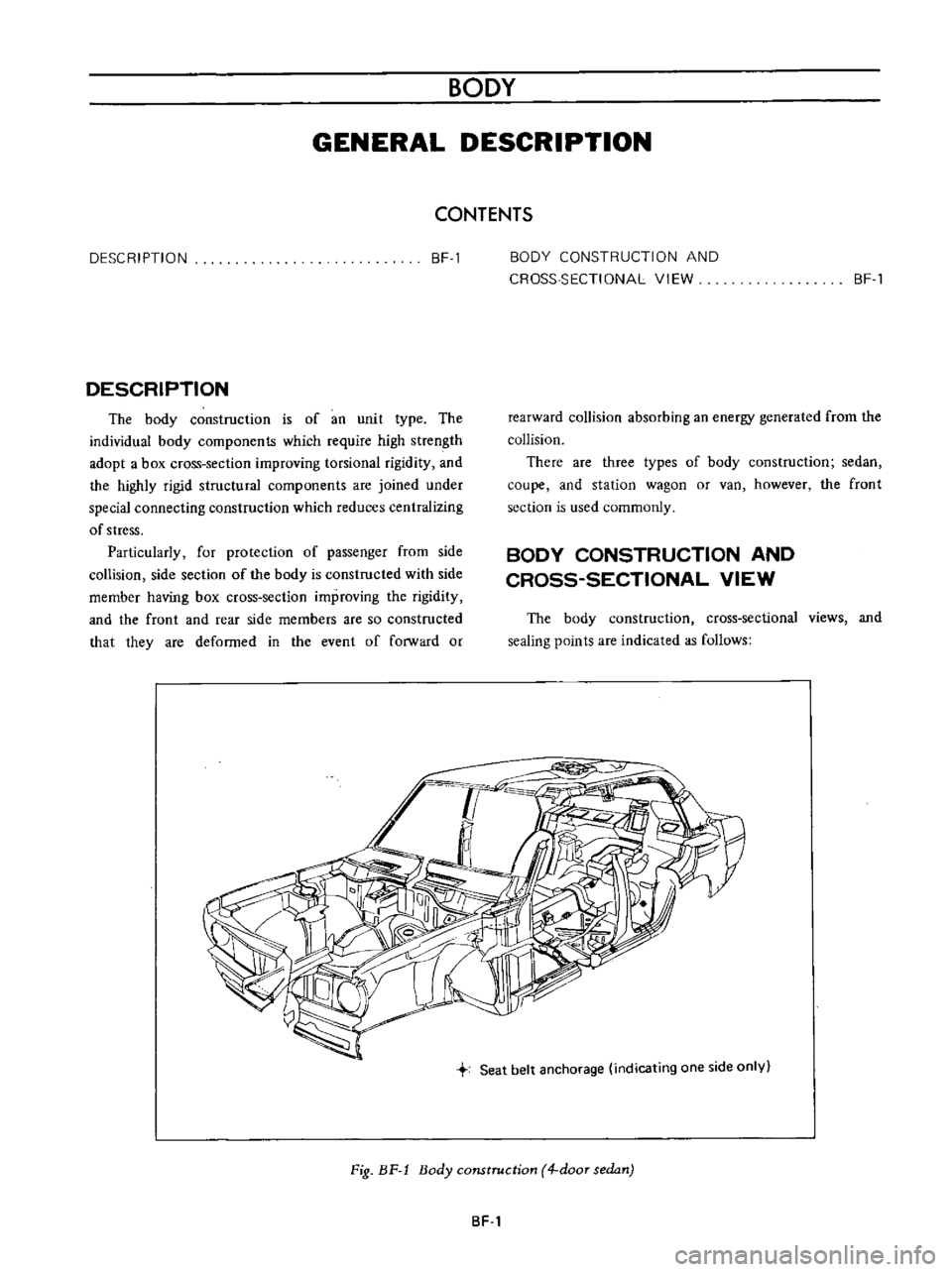
DESCRIPTION
The
body
construction
is
of
an
unit
type
The
individual
body
components
which
require
high
strength
adopt
a
box
cross
section
improving
torsional
rigidity
and
the
highly
rigid
structural
components
are
joined
under
special
connecting
construction
which
reduces
centralizing
of
stress
Particularly
for
protection
of
passenger
from
side
collision
side
section
of
the
body
is
constructed
with
side
member
having
box
cross
section
improving
the
rigidity
and
the
front
and
rear
side
members
are
so
constructed
that
they
are
deformed
in
the
event
of
forward
or
BODY
CONSTRUCTION
AND
CROSS
SECTIONAL
VIEW
BF
1
rearward
collision
absorbing
an
energy
generated
from
the
collision
There
are
three
types
of
body
construction
sedan
coupe
and
station
wagon
or
van
however
the
front
section
is
used
commonly
BODY
CONSTRUCTION
AND
CROSS
SECTIONAL
VIEW
The
body
construction
cross
sectional
views
and
sealing
points
are
indicated
as
follows
Seat
belt
anchorage
indicating
one
side
only
Fig
BF
1
Body
construction
4
door
sedan
BF
1
Page 192 of 513
BODY
t
I
j
1
ll
U0
L
5
f
llIr
7Jv4
i
L
rl
c
l
U
j
tr
l
yj
w
v1
r
J
V
1
1
k
I
J
7
z
cd
l
J
b
Y
lli
i
r
I
y
I
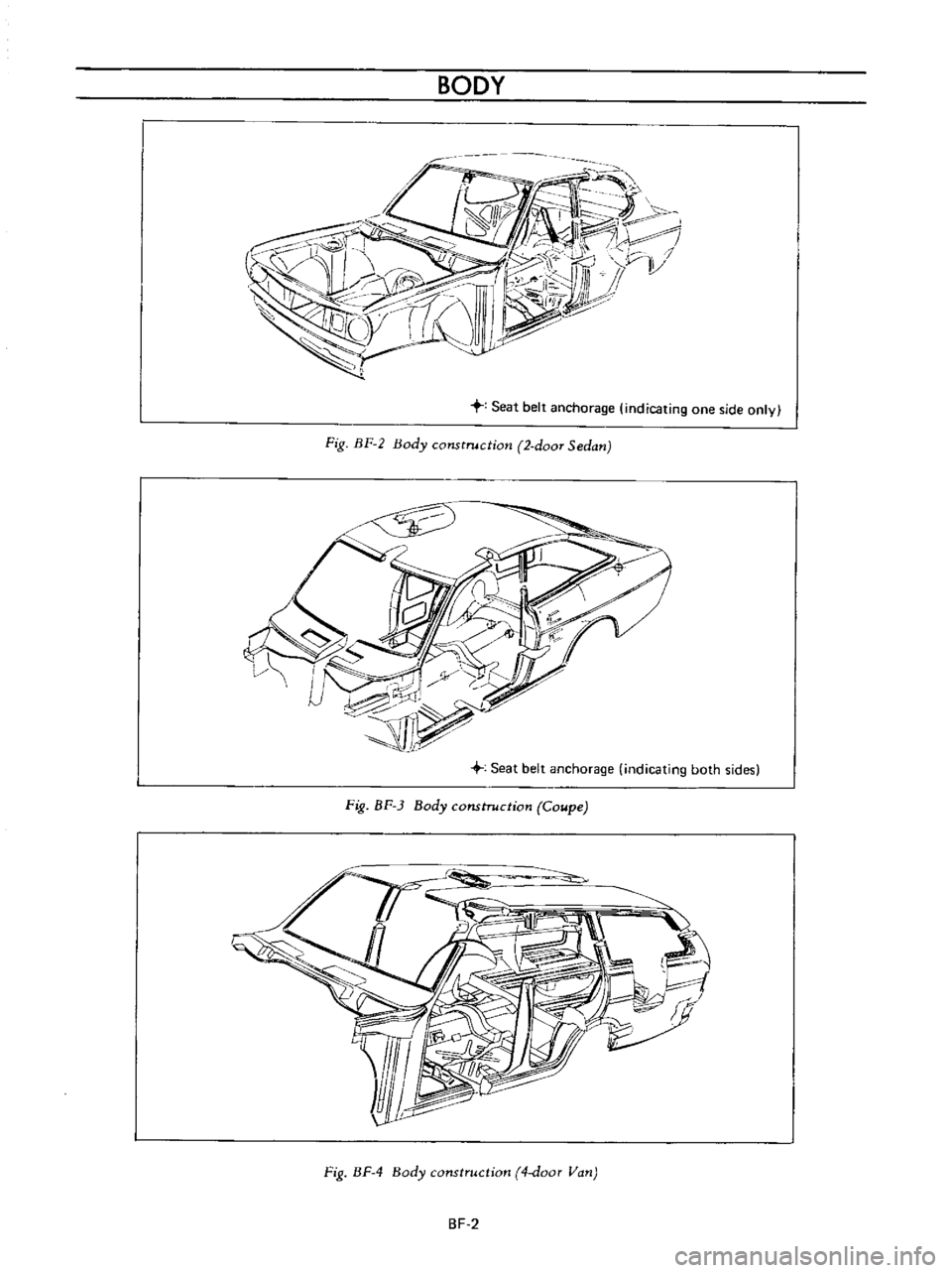
Seat
belt
anchorage
indicating
one
side
only
Fig
BF
2
Body
construction
2
doOT
Sedan
Fig
BF
3
Body
construction
Coupe
Fig
BF
4
Body
construction
4
door
Van
BF
2
Page 197 of 513
BODY
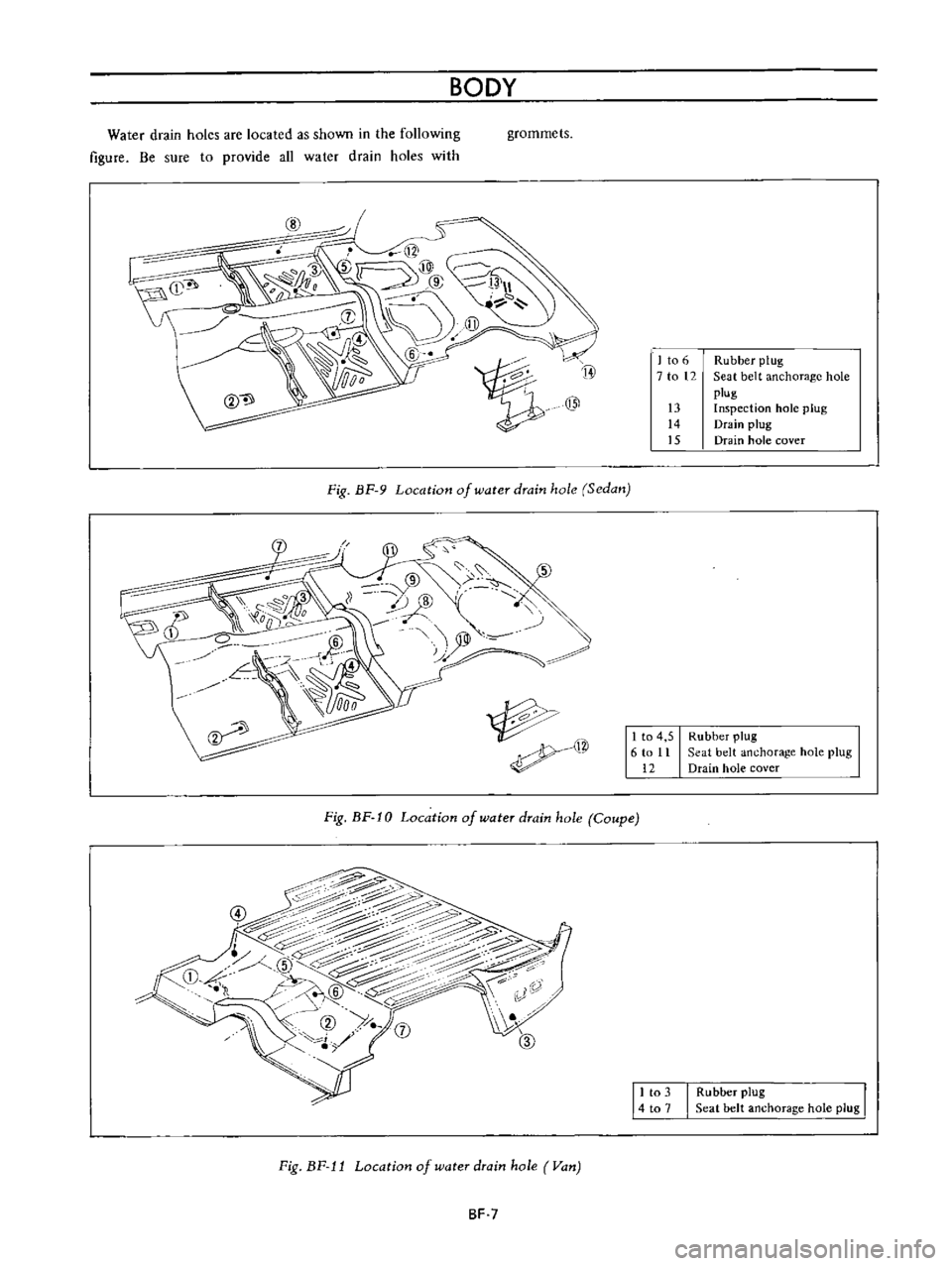
Water
drain
holes
are
located
as
shown
in
the
following
figure
Be
sure
to
provide
all
water
drain
holes
with
grommets
Fig
BF
9
Location
of
water
drain
hole
Sedan
r
I
S
S
@
y
j
B
om
q1
11
t
Fig
BF
10
Location
of
water
drain
hole
Coupe
4
C
t7
P
Cc
0
I
Y
j
G
27
il
j
e
@
Z
c
c
l
@
7
iJJ
j
Fig
BF
J
J
Location
of
water
drain
hole
Van
BF
7
I
to
6
Rubber
plug
7
to
12
Seat
belt
anchorage
hole
plug
13
Inspection
hole
plug
14
Drain
plug
15
Drain
hole
cover
1
to
4
5
6
to
11
12
Rubber
plug
Seat
belt
anchorage
hole
plug
Drain
hole
cover
11
to
3
I
Rubber
plug
I
4
to
1
Seat
belt
anchorage
hole
plug
Page 228 of 513
@
c
@
CD
w
1
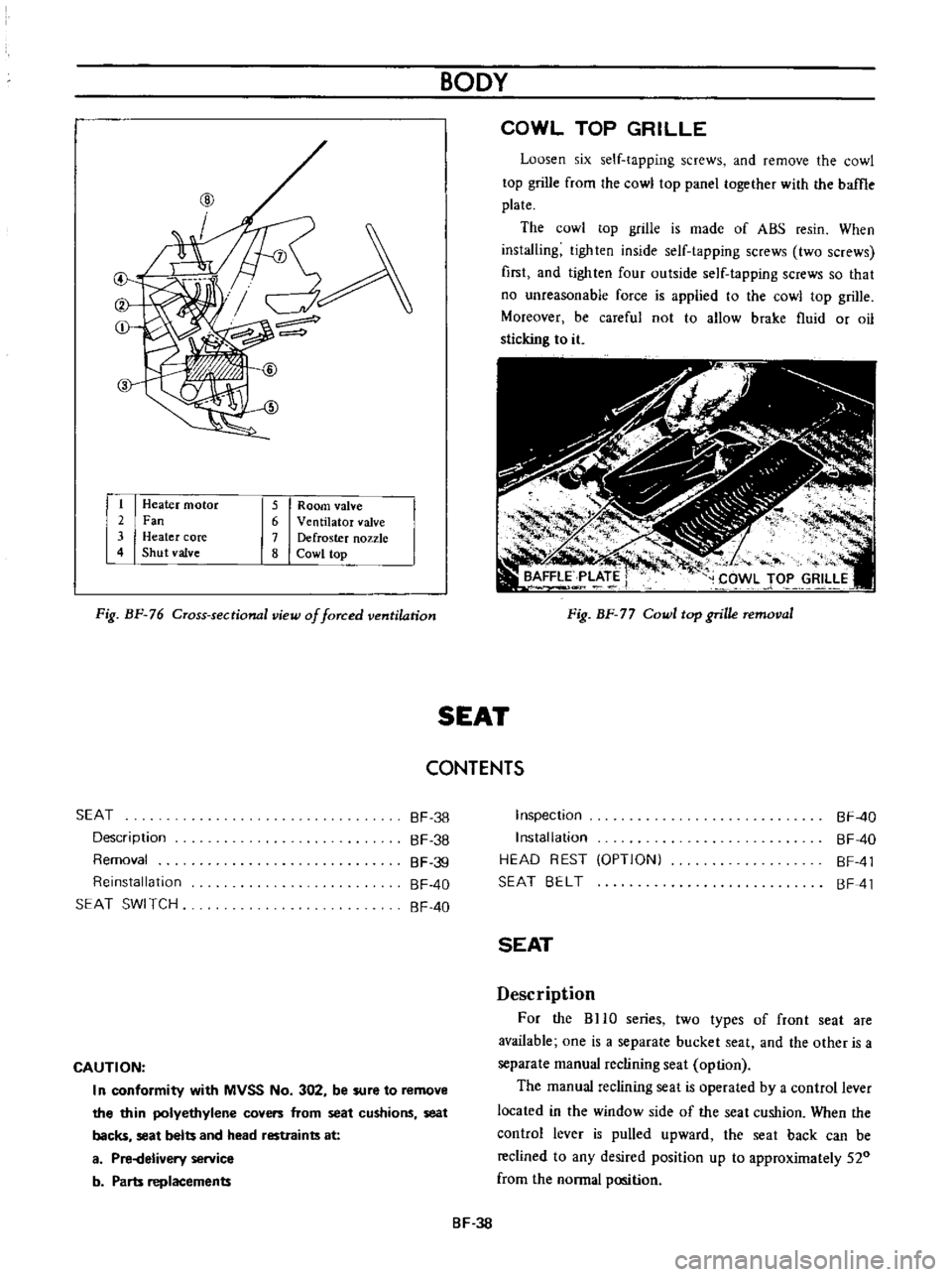
Heater
motor
2
Fan
3
Heater
core
4
Shut
valve
5
Room
valve
6
Ventilator
valve
7
Defroster
nozzle
8
Cowl
top
Fig
BF
76
Cross
sectional
view
of
forced
ventilation
BODY
COWL
TOP
GRILLE
Loosen
six
self
tapping
screws
and
remove
the
cowl
top
grille
from
the
cowl
top
panel
together
with
the
baffle
plate
The
cowl
top
grille
is
made
of
ABS
resin
When
installing
tighten
inside
self
tapping
screws
two
screws
first
and
lighten
four
outside
self
tapping
screws
so
that
no
unreasonable
force
is
applied
to
the
cowl
top
grille
Moreover
be
careful
not
to
allow
brake
fluid
or
oil
sticking
to
it
Fig
BF
77
Cowl
top
grille
removal
SEAT
CONTENTS
SEAT
Description
Removal
Reinstallation
SEAT
SWI
TCH
BF
38
BF
38
BF
39
BF
40
BF
40
CAUTION
I
n
conformity
with
MVSS
No
302
be
sure
to
remove
the
thin
polyethylene
covers
from
seat
cushions
seat
backs
seat
belts
and
head
restraints
at
a
Pi
Helivery
service
b
Parts
replacements
Inspection
Installation
HEAD
REST
OPTIONI
SEAT
BELT
BF
40
BF
40
BF
41
BF
41
SEAT
Description
For
the
BHO
series
two
types
of
front
seat
are
available
one
is
a
separate
bucket
seat
and
the
other
is
a
separate
manual
reclining
seat
option
The
manual
reclining
seat
is
operated
by
a
control
lever
located
in
the
window
side
of
the
seat
cushion
When
the
control
lever
is
pulled
upward
the
seat
back
can
be
reclined
to
any
desired
position
up
to
approximately
520
from
the
normal
position
BF
38
Page 231 of 513

j
L
CD
1
II
r
1
P
r
4vc
V
4
I
o
@
@
c
ID
I
HEAD
REST
OPTION
When
installing
head
rest
on
front
seat
remove
the
plug
on
the
seat
back
and
insert
the
head
rest
supports
into
the
holes
Fig
BF
86
Head
rest
BODY
SEAT
BELT
The
two
front
seat
belts
are
of
a
three
point
type
consisting
of
lap
and
shoulder
belts
The
two
rear
seat
belts
are
of
a
tow
point
type
The
lap
belts
of
all
seats
are
provided
with
automatic
locking
retractor
In
the
front
automatic
locking
retaractor
a
belt
switch
retractor
switch
micro
switch
for
the
seat
belt
warning
system
is
built
in
Notes
a
DO
NOT
attempt
repairs
on
lap
belt
retractor
mechanisms
Replace
defective
part
with
NEW
service
replacement
parts
b
DO
NOT
replace
one
belt
of
lap
belt
or
shou
Ider
belt
set
r
l
Scating
switch
for
assistant
seat
2
Seat
belt
switch
3
Automatic
locking
retractor
4
Inhibitor
switch
for
AfT
5
Neutral
switch
for
M
T
Fig
BF
87
Seat
belt
installing
positions
BF
41
Page 241 of 513
INSPECTION
Referring
to
the
wiring
diagram
check
the
wiring
harness
for
connection
with
electrical
equipment
and
connector
for
conned
ion
and
installation
When
checking
the
wiring
harness
note
the
following
matters
Connected
unit
should
not
be
loose
rusted
or
contaminated
2
Cable
insulator
cover
should
not
be
damaged
crack
ed
or
insulating
material
should
not
be
deteriorated
3
For
those
parts
which
are
grounded
through
the
installation
bolts
the
bolts
should
be
in
contact
with
the
body
completely
so
that
continuity
is
provided
in
between
the
body
and
bolts
4
Terminals
of
unit
through
which
current
flows
should
not
come
into
contact
with
other
metal
parts
5
No
erroneous
connection
should
be
present
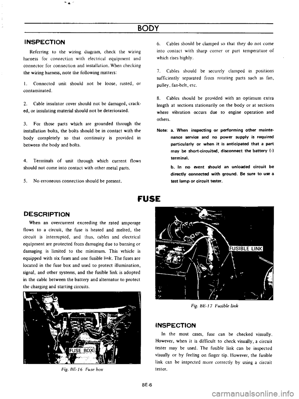
DESCRIPTION
When
an
overcunent
exceeding
the
rated
amperage
flows
to
a
circuit
the
fuse
is
heated
and
melted
the
circuit
is
interrupted
and
thus
cables
and
electrical
equipment
are
protected
from
damaging
due
to
burning
or
damaging
is
limited
to
the
minimum
This
vehicle
is
equipped
with
six
fuses
and
one
fusible
link
The
fuses
are
located
in
the
fuse
box
and
used
to
protect
illumination
signal
and
other
systems
and
the
fusible
link
is
adopted
in
the
cable
between
the
battery
and
alternator
to
protect
the
charging
and
starting
circuits
FiJ
BE
16
Fuse
box
BODY
6
Cables
should
be
damped
so
that
they
do
not
come
into
contact
with
sharp
corner
or
part
lernperature
of
which
rises
highly
7
Cables
should
be
securely
clamped
in
posItions
sufficiently
separated
from
rotating
parts
such
as
fan
pulley
fan
belt
etc
8
Cables
should
be
provided
with
an
optimum
extra
length
at
sections
stationarity
on
the
body
or
at
sections
where
vibration
occurs
due
to
engine
operation
and
others
Note
a
When
inspecting
or
performing
other
mainte
nance
service
and
no
power
supply
is
required
particularly
or
when
it
is
anticipated
that
a
part
may
be
short
circuited
disconnect
the
battery
H
terminal
b
In
no
event
should
an
unloaded
circuit
be
directly
connected
with
ground
Be
sure
to
use
a
test
lamp
or
circuit
tester
fUSE
Fig
BE
17
Fusible
link
INSPECTION
In
the
most
cases
fuse
can
be
checked
visually
However
when
it
is
difficult
to
check
visually
a
circuit
tester
may
be
used
The
fusible
link
can
be
inspected
visually
or
by
feeling
on
finger
tip
However
the
fusible
link
can
be
inspected
more
correctly
by
using
a
circuit
tester
BE
6
Page 306 of 513

EMISSION
CONTROL
AND
TUNE
UP
EMISSION
CONTROL
SYSTEM
AN
D
ENGINE
TUNE
UP
CONTENTS
BASIC
MECHANICAL
SYSTEM
ET
Checking
and
adjusting
dash
pot
Adjusting
intake
and
exhaust
valve
automatic
transmission
model
only
ET
9
clearances
ET
1
Checking
carburetor
return
spring
ET
9
Checking
and
adjustin9
drive
belt
ET
2
Checking
choke
mechanism
choke
valve
Retightening
cylinder
head
bolts
manifold
and
linkagel
ET
9
nuts
and
carburetor
securing
nuts
ET
2
Checking
anti
dieseling
solenoid
ET
9
Checking
engine
oil
ET
2
Replacing
fuel
filter
ET
10
Replacing
oil
filter
ET
3
Checking
fuel
lines
hoses
pipings
Changing
engine
coolant
L
L
C
ET
3
connections
etc
ET10
Checking
cooling
system
hoses
and
THROTTLE
OPENER
CONTROL
SYSTEM
ET
10
connections
ET
4
Checking
and
adjusting
throttle
opener
ET
13
Checking
vacuum
fittings
hoses
and
TRANSMISSION
CONTROLLED
VACUUM
connections
ET
4
ADVANCE
SYSTEM
ET
17
Checking
engine
compression
ET
4
Checking
electrical
advance
control
system
ET
19
Checking
exhaust
manifold
heat
control
AUTOMATIC
TEMPERATURE
CONTROL
AIR
valve
ET
5
CLEANER
A
T
C
AIR
CLEANER
ET
20
IGNITION
AND
FUEL
SYSTEM
ET
5
Replacing
carburetor
air
cleaner
filter
ET
20
Checking
battery
ET
5
Checking
hot
air
control
valve
ET
20
Checking
and
adjusting
ignition
timing
ET
5
CRANKCASE
EMISSION
CONTROL
Checking
or
replacing
distributor
breaker
SYSTEM
ET
22
point
condenser
and
spark
plugs
ET
6
Checking
or
replacing
PCV
valve
ET
23
Checking
distributor
ignition
wiring
and
Checking
ventilation
hoses
ET
23
ignition
coil
ET
7
EVAPORATIVE
EMISSION
CONTROL
Checking
distributor
cap
and
rotor
ET
7
SYSTEM
ET
23
Adjusting
carburetor
id
Ie
rpm
and
Checking
engine
compartment
hose
mixture
ratio
ET
8
connections
and
fuel
vapor
control
valves
ET
23
Checking
fuel
tank
vacuum
relief
valve
operation
ET
24
BASIC
MECHANICAL
SYSTEM
1
Start
engine
and
run
it
until
it
is
heated
to
operating
temperature
or
at
least
more
than
800C
I760F
of
engine
oil
temperature
then
stop
engine
Adjusting
intake
and
exhaust
valve
clearances
Valve
clearance
adjustment
should
be
made
while
engine
is
stationary
To
adjust
proceed
as
follows
2
Rotate
crankshaft
to
bring
No
1
cylinder
in
top
dead
center
on
its
compression
stroke
3
Remove
valve
rocker
cover
to
gain
access
to
valve
ET
1
Page 307 of 513
ENGINE
operating
mechanism
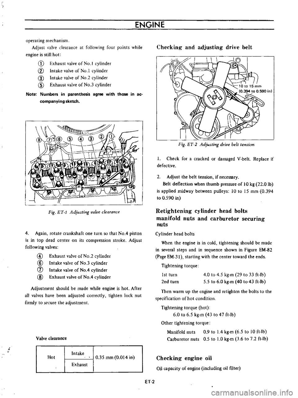
Adjust
valve
clearance
at
following
four
points
while
engine
is
still
hot
G
Exhaust
valve
of
No
1
cylinder
CV
Intake
valve
of
No
1
cylinder
CID
Intake
valve
of
No
2
cylinder
CID
Exhaust
valve
of
No
3
cylinder
Note
Numbers
in
parenthesis
agree
with
those
in
ac
companying
sketch
I
Fig
BY
1
Adjusting
valve
clearance
4
Again
rotate
crankshaft
one
turn
so
that
No
4
piston
is
in
top
dead
ce
lter
on
its
compression
stroke
Adjust
follnwing
valves
@
Exhaust
valve
of
No
2
cylinder
@
Intake
valve
of
No
3
cylinder
f
Intake
valve
of
No
4
cylinder
@
Exhaust
valve
of
No
4
cylinder
Adjustment
should
be
made
while
engine
is
hot
After
all
valves
have
been
adjusted
correctly
tighten
lock
nut
firmly
to
secure
the
adjustment
Vah
e
clearance
Hot
Intake
0
35
mm
0
014
in
Exhaust
Checking
and
adjusting
drive
belt
II
I
Fig
ET
2
Adjusting
drive
belt
tension
I
Check
for
a
cracked
or
damaged
V
belt
Replace
if
defective
2
Adjust
the
belt
tension
if
necessary
Belt
deflection
when
thumb
pressure
of
10
kg
22
0
lb
is
applied
midway
between
pulleys
10
to
15
mm
0
394
to
0
590
in
Retightening
cylinder
head
bolts
manifold
nuts
and
carburetor
securing
nuts
Cylinder
head
bolts
When
the
engine
is
in
cold
tightening
should
be
made
in
several
steps
and
in
sequence
shown
in
Figure
EM
82
page
EM
31
starting
with
the
center
toward
the
ends
Tightening
torque
1st
turn
2nd
turn
4
0
to
4
5
kg
m
29
to
33
ft
lb
5
5
to
6
0
kg
m
40
to
43
ft
lb
Then
warm
up
the
engine
and
retighten
the
bolts
to
the
specification
of
hot
condition
Tightening
torque
hot
6
0
to
6
5
kg
m
43
to
47
ft
lb
Other
tightening
torque
Manifold
nuts
0
9
to
14
kg
m
6
5
to
10
ft
lb
Carburetor
nuts
0
5
to
LO
kg
m
3
6
to
7
2
ft
lb
Checking
engine
oil
Oil
capacity
of
engine
including
oil
filter
ET
2