Page 330 of 513

EMISSION
CONTROL
AND
TUNE
UP
SERVICE
DATA
AND
SPECIFICATIONS
Valve
clearance
Hot
Intake
Exhaust
mm
in
rom
in
rom
in
kg
lb
0
35
0
014
0
35
0
014
10
to
15
0
394
to
0
591
10
22
Fan
belt
tension
Tightening
torque
Cold
Cylinder
head
bolts
kg
m
ft
lb
1st
turn
2nd
turn
Re
tightening
torque
Hot
Manifold
nuts
Carburetor
nuts
4
0
to
4
5
29
to
33
5
5
to
6
0
40
to
43
6
0
to
6
5
43
to
47
0
9
to
I
4
6
5
to
10
0
5
to
1
0
3
6
to
7
2
1
5
to
2
0
II
to
14
Spark
plugs
Oil
capacity
of
engine
including
oil
ftIter
Maximum
L
US
gal
Imp
gal
L
US
gal
Imp
gal
3
3
U
14
2
3
Ii
Minimum
Water
capacity
of
cooling
system
Without
heater
L
US
gal
Imp
gal
With
heater
L
US
gal
Imp
gal
4
2
1
U
4
9
I
4
11
12
5
to
14
5
I78
to
206
350
Compression
pressure
at
rpm
kg
em
psi
Battery
specific
gravity
Permissible
value
Fully
charged
value
at
200C
680F
Frigid
climates
Tropical
climates
Other
elima
tes
Over
1
22
Over
1
18
Over
1
20
1
28
1
23
1
26
Ignition
timing
degree
Distributor
50
B
T
D
C
Condenser
capacity
mm
in
degrees
IlF
Micro
Farad
0
45
to
0
55
0
018
to
0
022
49
to
55
0
22
5
Point
gap
Dwell
angle
Condenser
insulation
resistance
Mil
Mega
ohms
ET
25
Page 331 of 513

ENGINE
Spark
plugs
Cap
mm
in
0
8
to
0
9
0
03110
0
035
Idle
CO
ldie
speed
Manual
transmission
rpm
rpm
1
5
to
5
800
1
5
to
5
650
in
D
position
Automatic
transmission
Dash
pot
Setting
engine
speed
rpm
1
900
to
2
000
Throttle
opener
at
sea
level
Setting
vacuwn
pressure
Manual
transmission
Automatic
transmission
Setting
engine
speed
no
load
Servo
diaphragm
full
stroke
rpm
mm
in
500
to
540
19
7
to
21
3
480
to
520
18
9
to
20
5
1
650
to
1
850
5
0
1969
mmHg
in
Hg
mmHg
in
Hg
Theono
switch
Temperature
rises
from
low
to
high
oC
0
F
above
5
41
Flow
guide
valve
Opera
ting
pressure
mmHg
in
Hg
10
0
4
TROUBLE
DIAGNOSES
AND
CORRECTIONS
Troubles
Possible
causes
Remedies
CANNOT
CRANK
ENGINE
OR
SLOW
CRANKING
Improper
grade
oiL
Replace
with
proper
grade
oiL
Discharged
battery
Charge
battery
Defective
battery
Replace
Loosen
fan
belt
Adjust
Trouble
in
charge
system
Inspect
charge
system
Wiring
connection
trouble
in
starting
circuit
Correct
Defective
starter
switch
Repair
or
replace
Defective
starter
motor
Repair
or
replace
ET
26
I
Page 335 of 513

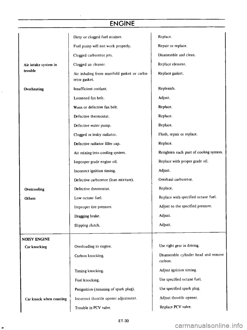
Air
intake
system
in
trouble
Overheating
Overcooling
Others
NOISY
ENGINE
Car
knocking
Car
knock
when
coasting
ENGINE
Diny
ur
clogged
fuel
strainer
Fuel
pump
will
not
work
properly
Clogged
carburetor
jets
Clogged
air
cleaner
Air
inhaling
from
manifold
gasket
or
carbu
retor
gasket
Insufficient
coolant
Loosened
fan
belt
Worn
or
defective
fan
belt
Defective
thermostat
Defective
water
pump
Clogged
or
leaky
radiator
Defective
radiator
filler
cap
Air
mixing
into
cooling
system
Improper
grade
engine
oil
Incorrect
ignition
timing
Defective
carburetor
lean
mixture
Defective
thermostat
Low
octane
fuel
Improper
tire
pressure
Dragging
brake
Slipping
clutch
Overloading
to
engine
Carbon
knocking
Timing
knocking
Fuel
knocking
Preignition
misusing
of
spark
plug
Incorrect
throttle
opener
adjustment
Trouble
in
PCV
valve
ET
30
Replace
Repair
or
replace
Disassemble
and
clean
Replace
element
Replace
gasket
Replenish
Adjust
Replace
Replace
Replace
Flush
repair
or
replace
Replace
Retighten
each
part
of
cooling
system
Replace
with
proper
grade
oil
Adjust
Overhaul
carburetor
Replace
Replace
with
specified
octane
fuel
Adjust
to
the
specified
pressure
Adjust
Adjust
Use
right
gear
in
driving
Disassemble
cylinder
head
and
remove
carbon
Adjust
ignition
timing
Use
specified
octane
fuel
Use
specified
spark
plug
Adjust
throttle
opener
Replace
PCV
valve
Page 372 of 513
ENGINE
27
Install
the
oil
pump
with
oil
filter
28
Install
the
alternator
fan
and
fan
belt
29
Install
the
fuel
pump
30
Install
the
distributor
assembly
Fig
EM
B7
Timing
maTk
Fig
EM
SS
Distributor
installation
EM
32
Notes
3
Set
the
No
1
piston
to
its
top
dead
center
of
the
compression
stroke
b
Before
installation
return
the
distributor
rotor
approximately
60
degrees
from
its
regular
posi
tion
Insert
the
assembly
meshing
the
distributor
drive
gear
and
driven
gear
After
installation
the
distributor
rotor
should
come
into
contact
with
the
mark
on
the
rotor
cap
fitting
as
shown
in
the
Figure
31
Install
the
spark
plugs
and
connect
the
distributor
to
plug
high
tension
lead
wire
32
Install
the
fuel
hoses
and
tubes
33
Install
the
clutch
cover
assembly
34
Install
the
engine
stingers
and
crankcase
ventilation
hose
35
Dismount
the
engine
from
the
working
stand
Install
the
engine
mountings
Page 388 of 513

ENGINE
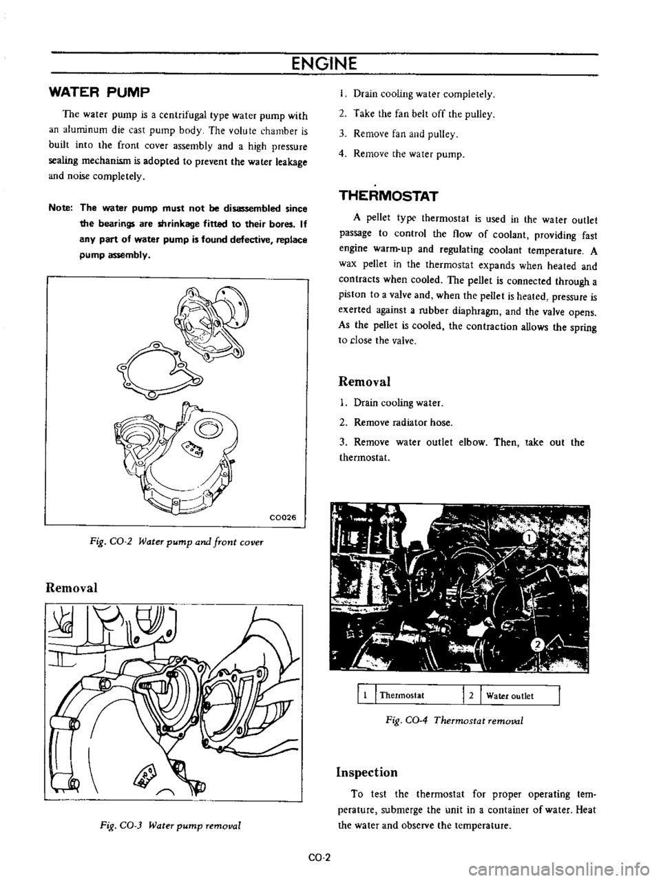
WATER
PUMP
The
water
pump
is
a
centrifugal
type
water
pump
with
an
aluminum
die
cast
pump
body
The
volute
chamber
is
built
into
the
front
cover
assembly
and
a
high
pressure
sealing
mechanism
is
adopted
to
prevent
the
water
leakage
and
noise
completely
Note
The
water
pump
must
not
be
disassembled
since
the
bearings
are
shrinkage
fitted
to
their
bores
If
any
part
of
water
pump
is
found
defective
replace
pump
assembly
o
C0026
Fig
CO
2
Water
pump
and
front
cover
Removal
Fig
CO
3
Water
pump
removal
Drain
cooling
water
completely
2
Take
the
fan
belt
off
the
pulley
3
Remove
fan
and
pulley
4
Remove
the
water
pump
THERMOSTAT
A
pellet
type
thermostat
is
used
in
the
wa
ter
outlet
passage
to
control
the
flow
of
coolant
providing
fast
engine
warm
up
and
regulating
coolant
temperature
A
wax
pellet
in
the
thermostat
expands
when
heated
and
contracts
when
cooled
The
pellet
is
connected
through
a
piston
to
a
valve
and
when
the
peUet
is
heated
pressure
is
exerted
against
a
rubber
diaphragm
and
the
valve
opens
As
the
pellet
is
cooled
the
contraction
allows
the
spring
to
close
the
valve
Removal
Drain
cooling
water
2
Remove
radiator
hose
3
Remove
water
outlet
elbow
Then
take
out
the
thermostat
11
I
Thermostat
12
Water
outlet
Fig
CO
4
Thermostat
removal
Inspection
To
test
the
thermostat
for
proper
operating
tern
perature
submerge
the
unit
in
a
container
of
water
Heat
the
water
and
observe
the
temperature
CO
2
Page 437 of 513
ENGINE
ElECTRICAL
SYSTEM
CD
@
@
@
y
@
1
Pulley
assembly
2
Front
cover
3
Front
bearing
4
Rotor
5
Rear
bearing
6
Stator
7
Rear
cover
8
Brush
assembly
9
Diode
set
pl
te
assembly
10
Diode
cover
Jl
Through
bolt
EE031
Fig
EE
29
Exploded
view
of
altematoT
REMOVAL
3
Loosen
the
adjusting
bolt
@
o
lL
1
Disconnect
the
negative
battery
terminal
2
Disconnect
two
lead
wires
and
connector
from
the
alternator
4
Remove
the
alternator
drive
belt
@
J
5
Remove
the
alternator
installation
bolt
@@@
6
Dismount
the
alternator
from
the
vehicle
EE033
Fig
EE
JO
Removal
of
pulley
DISASSEMBLY
l
Remove
the
pulley
nut
pulley
rim
fan
and
the
spacer
the
brush
holder
cover
Remove
the
brush
holder
forward
and
remove
the
brushes
together
with
the
brush
holder
2
Remove
the
brush
holder
fixing
screws
and
remove
Note
Do
not
disconnect
N
term
inal
from
stator
coil
lead
wire
EE
17
Page 446 of 513

ENGINE
at
4
to
5
V
Use
i
f
DC
voltmeter
and
set
up
a
circuit
as
shown
in
Figure
EE
56
EEQ58
L
W
R
IG
Will
r
AI
W
lli
r
N
Y
vge
I
JJ
Rtl
ublOr
I
I
Spanner
Cross
head
screwdriver
I
I
Adjusting
screw
Lock
nut
Vollm
lcl
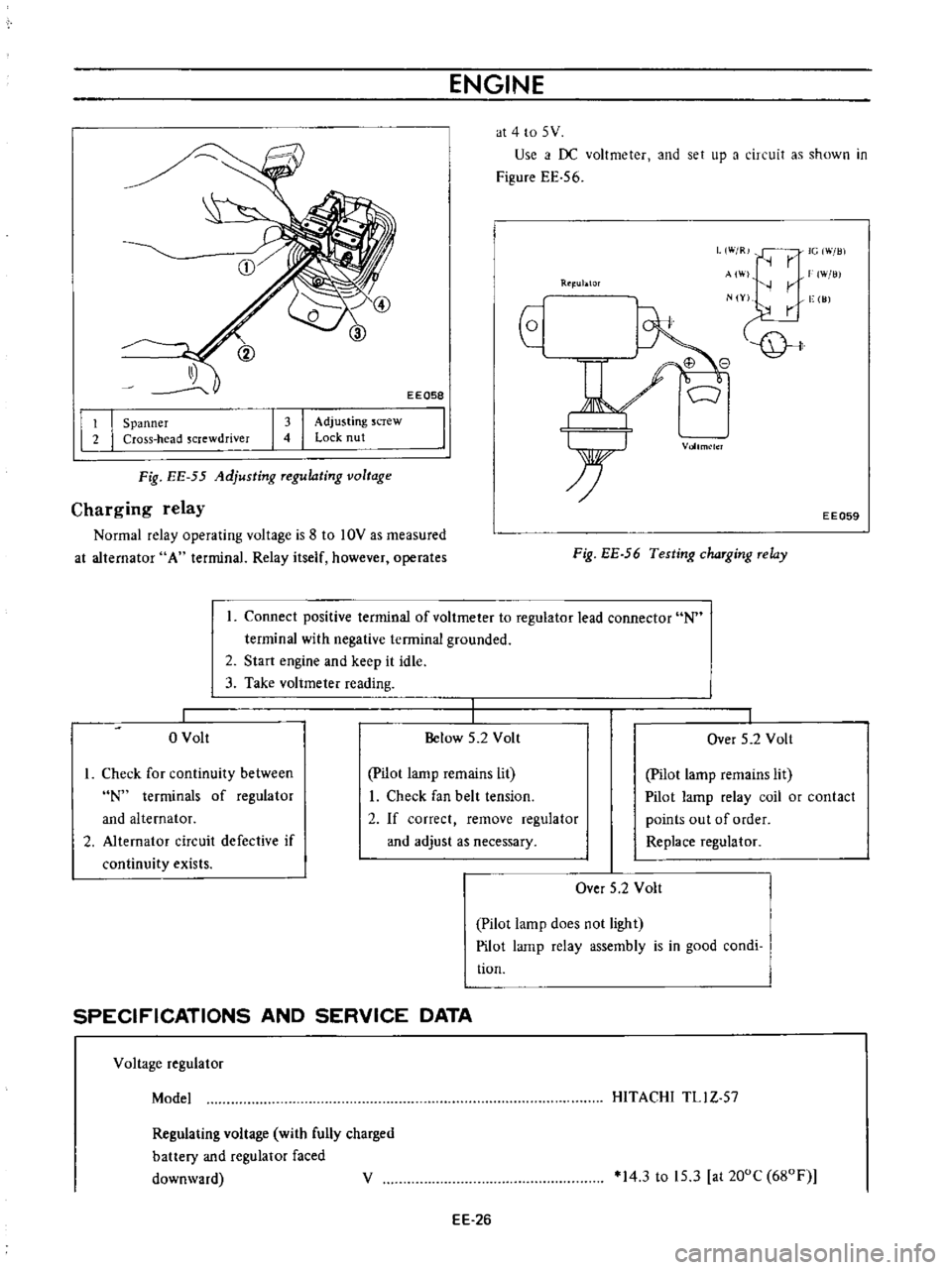
Fig
EE
55
Adjusting
Tegulating
voltage
Charging
relay
Normal
relay
operating
voltage
is
8
to
10V
as
measured
at
alternator
A
terminal
Relay
itself
however
operates
EE059
Fig
EE
56
Testing
chaTging
Telay
Connect
positive
terminal
of
voltmeter
to
regulator
lead
connector
N
terminal
with
negative
terminal
grounded
2
Start
engine
and
keep
it
idle
3
Take
voltmeter
reading
o
Volt
Below
5
2
Volt
I
Over
5
2
Volt
I
Check
for
continuity
between
N
terminals
of
regulator
and
alternator
2
Alternator
circuit
defective
if
continuity
exists
pilot
lamp
remains
lit
I
Check
fan
belt
tension
2
If
correct
remove
regulator
and
adjust
as
necessary
Pilot
lamp
remains
lit
Pilot
lamp
relay
coil
or
contact
points
out
of
order
Replace
regulator
Over
5
2
Volt
Pilot
lamp
does
not
light
Pilot
lamp
relay
assembly
is
in
good
condi
tion
SPECIFICATIONS
AND
SERVICE
DATA
Voltage
regulator
Model
HITACHI
TLl
Z
57
Regulating
voltage
with
fully
charged
battery
and
regulator
faced
downward
V
14
3
to
15
3
at
200C
680F
EE
26
Page 447 of 513

ENGINE
ELECTRICAL
SYSTEM
Rotor
coil
inserting
resistance
n
n
10
5
at
20DC
68DF
10
Voltage
coil
resistance
Core
gap
Point
gap
rnm
in
mm
in
31
40
0
6
to
1
0
0
0236
to
0
0394
0
3
to
0
4
0
0118
to
0
0157
Voltage
coil
series
resistance
Smoothing
resistance
n
Charge
relay
Release
voltage
Voltage
coil
resistance
V
4
2
to
5
2
at
N
terminal
n
37
8
at
20DC
68DF
mm
in
0
8
to
1
0
0
0315
to
0
0394
mm
in
0
4
to
0
6
0
0157
to
0
0236
Core
gap
Point
gap
Standard
temperature
gradient
D
015
VIDC
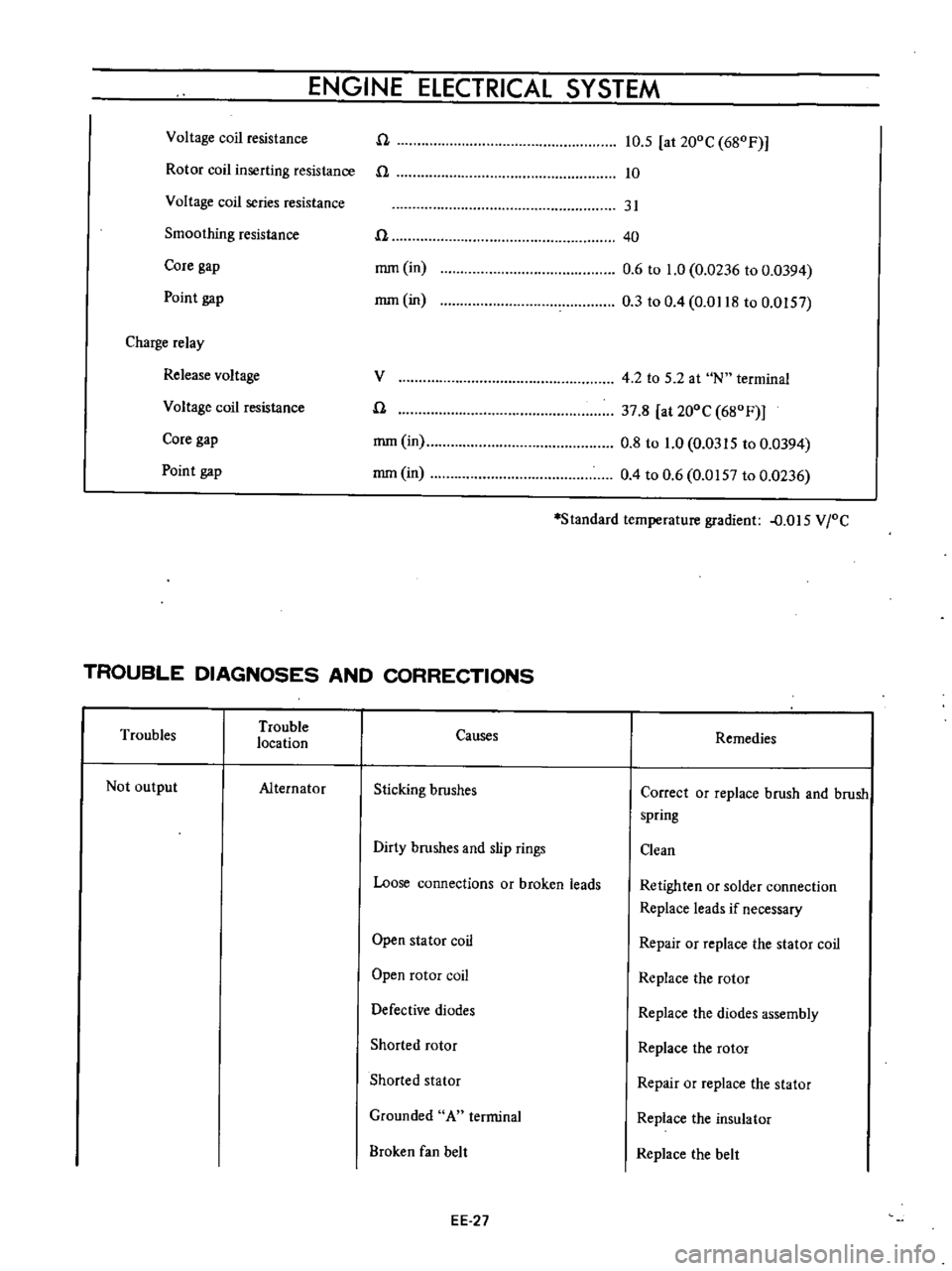
TROUBLE
DIAGNOSES
AND
CORRECTIONS
Troubles
Trouble
location
Causes
Remedies
Not
output
Alternator
Sticking
brushes
Correct
or
replace
brush
and
brush
spring
Dirty
brushes
and
slip
rings
Clean
Loose
connections
or
broken
leads
Retighten
or
solder
connection
Replace
leads
if
necessary
Open
stator
coil
Repair
or
replace
the
stator
coil
Open
rotor
coil
Replace
the
rotor
Defective
diodes
Replace
the
diodes
assembly
Shorted
rotor
Replace
the
rotor
Shorted
stator
Repair
or
replace
the
stator
Grounded
A
terminal
Replace
the
insulator
Broken
fan
belt
Replace
the
belt
EE
27