1973 DATSUN B110 oil level
[x] Cancel search: oil levelPage 55 of 513

c
Inspection
and
adJu
Stmenf
trouble
first
check
the
linhge
f
no
1
i
jI
fect
is
found
in
the
lin1
age
check
of
manu
a
l
liiiJ
i
the
inhibitor
switch
Th
d
1F
aI
S
t
th
I
I
f
e
a
JU
i
J
u
epara
e
e
range
se
eet
ever
rom
Iy
important
ii
s3
ns
etion
of
oil
the
lower
shift
rod
and
turn
the
range
1
level
for
the
automatiC
tran
smission
select
lever
to
N
Therefore
great
care
should
be
exer
Note
In
the
position
N
the
slot
of
cised
because
defective
adjustment
will
the
manual
shaft
is
vertical
result
in
the
breakdown
of
the
trans
By
the
use
of
the
tester
check
the
two
bIack
yellow
BY
wires
from
the
inhibitor
switch
in
the
ranges
N
and
P
and
the
two
red
bIack
RB
wires
in
the
range
R
for
continuity
Turn
range
select
lever
to
both
directions
from
each
lever
set
position
and
check
each
continuity
range
It
is
normal
if
the
electricity
is
on
while
the
lever
is
within
an
angle
of
about
3
0
on
both
sides
from
each
lever
set
line
How
ever
if
its
continuity
range
is
obvi
ously
unequal
on
both
sides
the
adjustment
is
required
f
any
malfunction
is
found
un
screw
the
fastening
nut
of
the
range
selector
lever
and
two
fastening
bolts
of
the
switch
body
and
then
remove
the
machine
screw
under
the
switch
body
Adjust
the
manual
shaft
correct
ly
to
the
position
N
by
means
of
the
selector
lever
When
the
slot
of
the
shaft
becomes
vertical
the
detent
works
to
position
the
shaft
correctly
with
a
click
sound
Move
the
switch
slightly
aside
so
that
the
screw
hole
will
be
aligned
with
the
pin
hole
of
the
internal
rotor
combined
with
the
manual
shaft
and
check
their
alignment
by
inserting
a
1
5
0101
0
0591
in
diameter
pin
into
the
holes
If
the
alignment
is
made
correct
1
5ten
the
switch
body
with
the
bolts
pull
out
the
pin
and
tighten
up
the
screw
again
into
the
hole
and
fasten
the
selector
lever
as
before
Check
over
again
the
continuity
with
the
tester
If
the
malfunction
still
remains
replace
the
inhibitor
switch
mission
Inspection
Pull
the
selector
lever
toward
you
and
turn
it
so
far
as
p
to
1
range
where
clicks
will
be
felt
by
hand
This
is
the
detent
of
manual
valve
in
the
body
and
indicates
the
correct
posi
tion
of
the
lever
Inspect
whether
the
pointer
of
selector
dial
corresponds
to
this
point
and
also
whether
the
lever
comes
in
alignment
with
the
stepping
of
posi
tion
plate
when
it
is
released
Adjustment
This
procedure
can
be
accom
plished
by
referring
to
Removal
and
nstallation
Checking
and
adjusting
inhibitor
switch
The
inhibitor
switch
serves
to
light
the
reverse
lamp
in
the
range
R
of
the
transmission
operation
and
also
to
rotate
the
starter
motor
in
the
ranges
N
and
P
j
r@
I
If
r
f
B
@
I
Jt
@
@
c
v@
i
r
fji
AT109
1
Inhibitor
switch
2
Manual
shaft
3
Washer
4
Nut
5
Manual
plate
Fig
AT
II
0
Con
truction
of
inhibitor
witch
6
Washer
7
Nut
8
Inhibitor
switch
9
Range
select
lever
Check
whether
the
reverse
lamp
and
the
starter
motor
operate
normal
ly
in
these
ranges
If
there
is
any
t
ki
A
mm
ATIC
TRANSMISSION
STALL
TEST
The
purpose
of
this
test
is
to
check
the
transmission
and
engine
for
trou
ble
by
measuring
the
maximwn
num
bers
of
revolutions
of
the
engine
while
vehicle
is
held
in
a
stalled
condition
and
the
carburetor
is
in
full
throttle
operation
with
the
selector
lever
in
AT
51
rang
s
D
2
and
I
respectively
and
by
com
pairing
the
measured
re
sults
with
the
standard
values
Standard
stall
revolution
1
750
to
2
000
rpm
Components
to
be
tested
and
test
items
1
Clutches
brake
and
band
in
trans
mission
for
slipping
2
Torque
converter
for
function
3
Engine
for
overall
property
Stall
test
procedures
Before
testing
check
the
enigne
oil
and
torque
converter
oil
warm
up
the
engine
cooling
water
to
the
suitable
temperature
by
warming
up
ope
ration
at
1
200
rpm
with
the
selector
lever
in
the
range
P
for
several
minutes
and
warm
up
the
torque
converter
oil
to
the
suitable
temperature
60
to
IOOoC
140
to
2120F
1
Mount
the
engine
tachometer
at
a
location
that
allows
good
visibility
from
the
driver
s
seat
and
put
a
mark
on
specified
revolutions
on
the
meter
2
Secure
the
front
and
rear
wheels
completely
with
chocks
and
apply
the
hand
brake
Be
sure
to
depress
the
brake
pedal
firmly
with
the
left
foot
before
depressing
down
the
accelerator
pedal
3
Throw
the
selector
lever
into
the
range
D
4
Slowly
depress
the
accelerator
pedal
down
till
the
throttle
valve
is
fully
opened
Quickly
read
and
record
the
engine
revolution
when
the
engine
begins
to
rotate
steadily
and
then
release
the
accelerator
pedal
5
Turn
the
selector
lever
into
N
and
operate
the
enigne
at
approxi
mately
1
200
rpm
for
more
than
one
minute
to
cool
down
the
torque
con
verter
oil
and
coolant
6
Make
similar
stall
tests
in
the
ranges
2
I
and
R
Note
The
stall
test
operation
as
spec
ified
in
the
item
4
should
be
made
within
five
seconds
If
it
takes
too
long
the
oil
deterio
rates
and
the
clutches
brake
Page 58 of 513

Judgement
in
measurmg
line
pressure
I
Low
idling
line
pressures
in
the
ranges
D
2
loR
and
P
It
can
be
artributed
to
trouble
in
the
pressure
supply
system
or
too
low
output
of
power
caused
by
1
A
worn
oil
pump
2
An
oil
pressure
leakage
in
the
oil
pump
valve
body
or
case
3
A
sticking
regulator
valve
2
Low
idling
line
pressures
in
cer
tain
ranges
only
It
is
caused
pressumabIy
by
an
oil
leakage
in
the
devices
or
circuits
con
nected
to
the
relevant
ranges
1
When
there
is
an
oil
leakage
in
the
rear
clutch
and
governor
the
line
pressures
in
D
2
and
I
are
low
but
the
pressure
is
normal
in
R
2
When
an
oil
leakage
occurs
in
the
low
and
reverse
brake
circuit
the
line
pressures
in
R
and
p
are
low
but
the
pressure
is
normal
in
0
2
and
I
3
High
idling
line
pressures
It
is
presumed
to
be
caused
by
an
increased
vacuum
throttle
pressure
owing
to
a
leakage
in
the
vacuum
tube
or
diaphragm
or
by
an
increased
line
pressure
due
to
a
sticking
regulator
CHASSIS
valve
Vacuum
leakage
is
checked
by
di
reetly
measuring
the
negative
pressure
after
removing
the
vacuum
pipe
A
puncture
of
the
vacuum
dia
phragm
can
be
easily
ascertained
because
the
torque
converter
oil
is
absorbed
into
the
engine
and
the
exhaust
pipe
blows
up
the
white
smoke
4
Checking
items
when
the
line
pressure
is
increasing
In
trJs
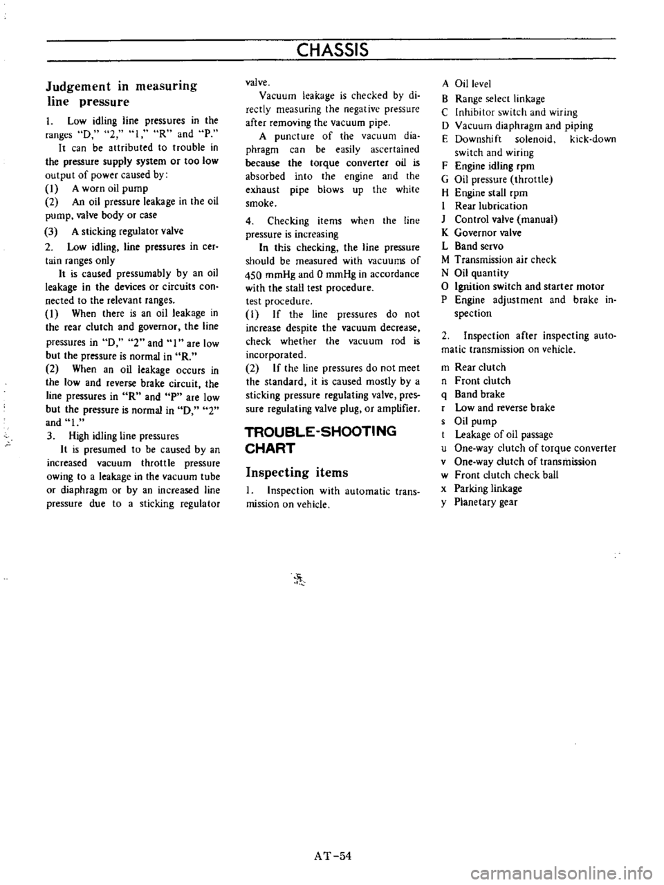
checking
the
line
pressure
should
be
measured
with
vacuums
of
450
mmHg
and
0
mmHg
in
accordance
with
the
stall
test
procedure
test
procedure
1
If
the
line
pressures
do
not
increase
despite
the
vacuum
decrease
check
whether
the
vacuum
rod
is
incorporated
2
If
the
line
pressures
do
not
meet
the
standard
it
is
caused
mostly
by
a
sticking
pressure
regulating
valve
pres
sure
regulating
valve
plug
or
amptifier
TROUBLE
SHOOTING
CHART
Inspecting
items
1
Inspection
with
automatic
trans
mission
on
vehicle
J
AT
54
A
Oil
level
B
Range
selecr
linkage
C
Inhibitor
switch
and
wiring
D
Vacuum
diaphragm
and
piping
E
Downshift
solenoid
kick
down
switch
and
wiring
F
Engine
idling
rpm
G
Oil
pressure
throttle
H
Engine
stall
rpm
I
Rear
lubrication
J
Control
valve
manual
K
Governor
valve
L
Band
servo
M
Transmission
air
check
N
Oil
quantity
o
Ignition
switch
and
starter
motor
P
Engine
adjustment
and
brake
in
spection
2
Inspection
after
inspecting
auto
matic
transmission
on
vehicle
m
Rear
clutch
n
Front
clutch
q
Band
brake
r
Low
and
reverse
brake
s
Oil
pump
Leakage
of
oil
passage
u
One
way
clutch
of
torque
converter
v
One
way
clutch
of
transmission
w
Front
clutch
check
ball
x
Parking
linkage
y
Planetary
gear
Page 62 of 513

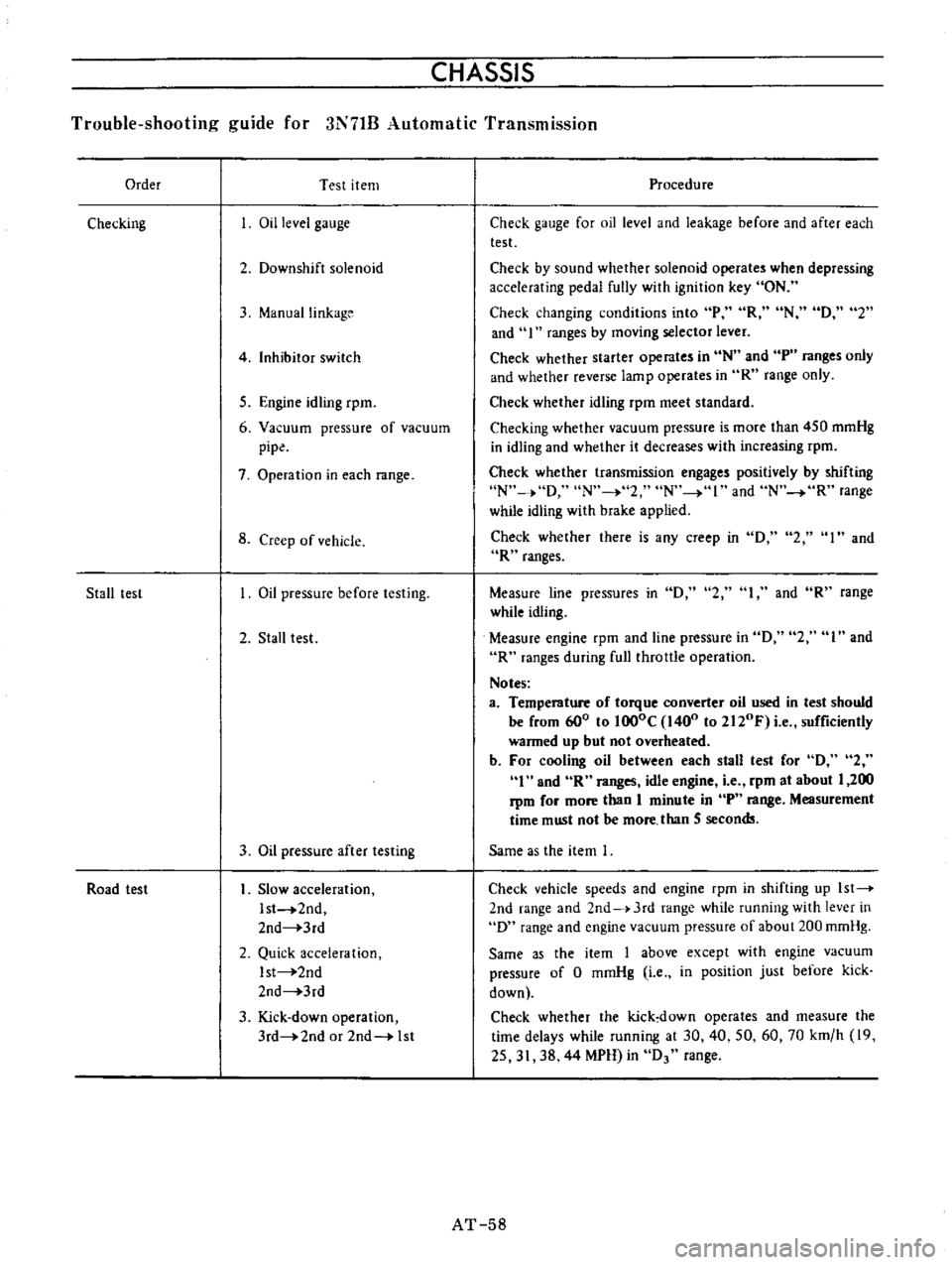
CHASSIS
Trouble
shooting
guide
for
3N71B
Automatic
Transmission
Order
Test
item
Checking
Oil
level
gauge
2
Downshift
solenoid
3
ManuaIlinkage
4
Inhibitor
switch
5
Engine
idling
rpm
6
Vacuum
pressure
of
vacuum
pipe
7
Operation
in
each
range
8
Creep
of
vehicle
Stall
lest
Oil
pressure
before
testing
2
Stall
test
3
Oil
pressure
after
testing
Road
test
Slow
acceleration
Ist
2nd
2nd
3rd
2
Quick
acceleration
Ist
2nd
2nd
3rd
3
Kick
down
operation
3rd
2nd
or
2nd
1st
Procedure
Check
gauge
for
oil
level
and
leakage
before
and
after
each
test
Check
by
sound
whether
solenoid
operates
when
depressing
accelerating
pedal
fully
with
ignition
key
ON
Check
changing
conditions
into
P
R
N
D
2
and
I
ranges
by
moving
selector
lever
Check
whether
starter
operates
in
N
and
tp
ranges
only
and
whether
reverse
lamp
operates
in
R
range
only
Check
whether
idling
rpm
meet
standard
Checking
whether
vacuum
pressure
is
more
than
450
mmHg
in
idling
and
whether
it
decreases
with
increasing
rpm
Check
whether
transmission
engages
positively
by
shifting
N
o
D
N
2
N
I
and
N
R
range
while
idling
with
brake
applied
Check
whether
there
is
any
creep
in
D
2
I
and
R
ranges
2
1
and
R
range
Measure
line
pressures
in
D
while
idling
Measure
engine
rpm
and
line
pressure
in
D
2
I
and
R
ranges
during
fullthrallIe
operation
Notes
a
Temperature
of
torque
converter
oil
used
in
test
should
be
from
600
to
lOOoC
1400
to
2120F
i
e
sufficiently
warmed
up
but
not
overheated
b
For
cooling
oil
between
each
stall
test
for
D
2
1
and
R
ranges
idle
engine
i
e
rpm
at
about
1
200
rpm
for
more
than
1
minute
in
P
range
Measurement
time
must
not
be
more
than
5
secon
Same
as
the
item
I
Check
vehicle
speeds
and
engine
rpm
in
shifting
up
1st
2nd
range
and
2nd
J
3rd
range
while
running
with
lever
in
D
range
and
engine
vacuum
pressure
of
about
200
mmHg
Same
as
the
item
1
above
except
with
engine
vacuum
pressure
of
0
mmHg
i
e
in
position
just
before
kick
down
Check
whether
the
kick
down
operates
and
measure
the
time
delays
while
running
at
30
40
50
60
70
km
h
19
25
31
38
44
MPH
in
D
range
AT
58
Page 149 of 513

Pedal
yields
under
slight
pressure
Excessive
pedal
travel
All
brakes
drag
One
brake
drags
Unbalanced
brakes
BRAKE
Use
of
a
brake
fluid
with
a
boiling
point
which
is
too
low
Reservoir
filler
cap
ven
t
hole
clogged
This
promotes
a
vacuum
in
master
cylinder
that
sucks
in
air
through
rear
seal
Deteriorated
check
valve
External
leaks
Master
cylinder
leaks
through
primary
cap
System
has
not
been
bled
Improperly
adjusted
clearance
Fluid
level
in
master
cylinder
is
too
low
Thermal
expansion
of
drums
due
to
over
heating
Insufficient
shoe
tlrdrum
clearance
Weak
shoe
return
springs
Brake
shoe
return
no
free
travel
Seized
master
cylinder
piston
Loose
or
damaged
wheel
bearings
Weak
broken
or
unhooked
brake
shoe
return
springs
Insufficient
clearance
between
brake
shoe
and
drum
Grease
or
oil
on
linings
Seized
piston
in
wheel
cylinder
Tires
improperly
inflated
Loose
wheel
bearing
BR
25
Change
with
the
specified
brake
fluid
and
bleed
system
Clean
reservoir
filler
cap
and
bleed
the
system
Fit
a
new
check
valve
and
bleed
the
system
Check
master
cylinder
piping
and
wheel
cylinder
for
leaks
and
make
necessary
re
pairs
Overhaul
master
cylinder
Bleed
the
system
Adjust
shoe
to
drum
clearance
Full
up
with
specified
brake
fluid
Bleed
the
system
if
required
Allow
drums
to
cool
off
Check
brake
shoe
linings
and
drums
Replace
damaged
parts
Adjust
clearance
Replace
the
springs
Adjust
pedal
height
Service
the
master
cylinder
replace
the
piston
and
bleed
the
system
Adjust
or
replace
wheel
bearings
Replace
spring
Adjust
brakes
Clean
brake
mechanism
replace
lining
and
correct
cause
of
grease
or
oil
getting
on
lining
Service
the
wheel
cylinder
and
bleed
the
system
Inflate
tires
to
correct
pressure
Adjust
wheel
bearing
Page 254 of 513

BODY
ELECTRICAL
SPEEDOMETER
The
speedometer
is
equipped
with
a
total
odometer
which
records
travelled
distance
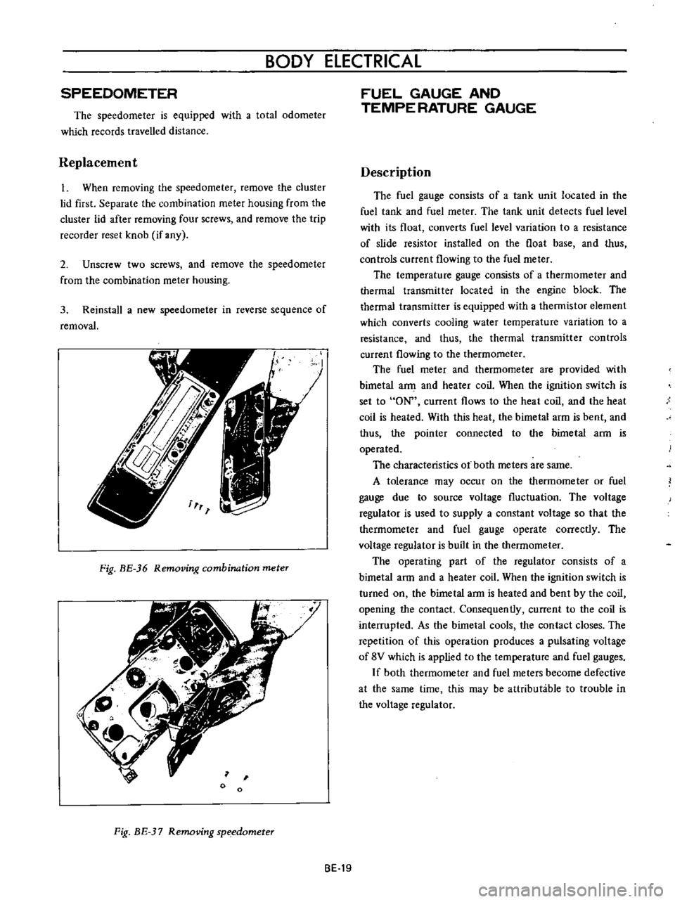
Replacement
1
When
removing
the
speedometer
remove
the
cluster
lid
first
Separate
the
combination
meter
housing
from
the
cluster
lid
after
removing
four
screws
and
remove
the
trip
recorder
reset
knob
if
any
2
Unscrew
two
screws
and
remove
the
speedometer
from
the
combination
meter
housing
3
Reinstall
a
new
speedometer
in
reverse
sequence
of
removal
Fig
BE
36
Removing
combination
meter
o
Fig
BE
37
Removing
sp
edometer
FUEL
GAUGE
AND
TEMPE
RATURE
GAUGE
Description
The
fuel
gauge
consists
of
a
tank
unit
located
in
the
fuel
tank
and
fuel
meter
The
tank
unit
detects
fuel
level
with
its
float
converts
fuel
level
variation
to
a
resistance
of
slide
resistor
installed
on
the
float
base
and
thus
controls
current
flowing
to
the
fuel
meter
The
temperature
gauge
consists
of
a
thermorneter
and
thermal
transmitter
located
in
the
engine
block
The
thermal
transmitter
is
equipped
with
a
thermistor
element
which
converts
cooling
water
temperature
variation
to
a
resistance
and
thus
the
thermal
transmitter
controls
current
flowing
to
the
thermometer
The
fuel
rneter
and
thermometer
are
provided
with
bimetal
a
and
heater
coil
When
the
ignition
switch
is
set
to
ON
current
flows
to
the
heat
coil
and
the
heat
coil
is
heated
With
this
heat
the
bimetal
arm
is
bent
and
thus
the
pointer
connected
to
the
bimetal
ann
is
operated
The
characteristics
ot
both
meters
are
same
A
tolerance
may
occur
on
the
thermometer
or
fuel
gauge
due
to
source
voltage
fluctuation
The
voltage
regulator
is
used
to
supply
a
constant
voltage
so
that
the
therrnorneter
and
fuel
gauge
operate
correctly
The
voltage
regulator
is
built
in
the
thermometer
The
operating
part
of
the
regulator
consists
of
a
bimetal
arm
and
a
heater
coil
When
the
ignition
switch
is
turned
on
the
birnetal
arm
is
heated
and
bent
by
the
coil
opening
the
contact
Consequently
current
to
the
coil
is
interrupted
As
the
bimetal
cools
the
contact
closes
The
repetition
of
this
operation
produces
a
pulsating
voltage
of
8V
which
is
applied
to
the
ternperature
and
fuel
gauges
If
both
thermometer
and
fuel
meters
become
defective
at
the
same
time
this
may
be
attributable
to
trouble
in
the
voltage
regulator
BE
19
Page 260 of 513

BODY
ELECTRICAL
Improper
cable
contact
Oil
pressure
and
ignition
warning
lamps
Condition
Oil
pressure
Want
ing
lamp
The
lamp
does
not
ligh
t
when
the
ignition
switch
is
set
to
ON
Probable
cause
Blown
off
fuse
or
faulty
contact
Broken
lamp
bulb
fIlarnent
or
faulty
cable
contact
Defective
oil
pressure
switch
The
lamp
does
not
Oil
pressure
is
too
low
go
out
while
the
engine
is
being
operated
Lack
of
engine
oil
Defective
oil
pressure
switch
Ignition
warning
lamp
The
lamp
does
not
light
when
the
ignition
switch
is
set
to
ON
Blown
off
fuse
or
faulty
contact
Burnt
out
light
bulb
filarnent
or
faulty
cable
contact
The
fuel
rneter
indicates
a
level
slightly
lower
than
the
actual
level
Method
of
inspection
Check
the
fuse
for
fusing
and
faulty
contact
The
warning
lamp
does
not
light
when
oil
pressure
switch
yellow
black
cable
is
grounded
The
warning
lamp
lights
through
the
above
inspection
Inspect
the
engine
oil
pressure
system
Check
oil
level
Continuity
exists
on
the
oil
pres
sure
switch
when
the
engine
is
being
operated
Check
the
fuse
for
fusing
and
faulty
contact
The
pilot
lamp
does
not
light
when
the
voltage
regulator
con
nector
is
disconnected
the
white
red
cable
is
grounded
and
the
ignition
switch
is
set
to
ON
BE
25
Check
the
cable
from
the
fuel
meter
to
the
tank
unit
for
cable
being
about
to
break
poor
contact
and
faulty
grounding
and
repair
as
required
Corrective
action
Replace
after
corree
ting
the
fuse
the
cause
if
fused
Check
the
light
bulb
for
burnt
out
fIla
ment
and
replace
as
required
Replace
the
oil
pres
sure
switch
Add
oil
Replace
the
oil
pres
sure
switch
Repair
or
replace
as
required
Check
the
bulb
for
burnt
out
fIlament
and
replace
as
re
quired
Page 303 of 513

GENERAL
INFORMATION
NISSAN
LONG
LIFE
COOLANT
L
L
C
The
cooling
system
has
been
filled
at
factory
with
the
Long
Life
Coolant
L
L
C
and
water
for
aU
season
protection
This
coolant
provides
freezing
protection
to
150C
50F
in
a
30
Long
Life
Coolant
ratio
and
also
protects
the
engine
against
corrosion
If
outside
tempera
ture
falls
down
to
350C
3IOF
fill
a
50
50
mixture
of
the
Long
Life
Coolant
and
water
The
Long
Life
Coolant
is
an
ethylene
glycol
base
product
containing
any
glyc
erine
ethyl
or
methyl
alcohoL
The
Long
Life
Coolant
must
not
be
mixed
with
any
other
product
scale
nor
sediment
accumulated
in
water
jacket
or
radiator
adverse
ly
affects
heat
radiation
efficiency
When
the
coolant
is
changed
the
system
should
be
thoroughly
flushed
out
by
opening
the
two
drain
plugs
one
at
the
bottom
of
the
radiator
and
the
other
at
the
left
side
of
the
cylinder
block
until
clean
water
comes
out
Always
use
clean
soft
water
in
the
radiator
for
filling
the
radiator
DC
OF
01321
30
1
221
I
I
I
I
1
I
I
I
10
20
30
40
50
10
14
20
1
4
40
1
401
50
581
Fig
GI
13
Protection
concentration
Boiling
point
Percent
0
9
kg
cm2
Freeze
coneen
Sea
level
cooling
sys
protection
tratioo
tern
pressure
30
1060C
1240C
15OC
2210
F
2550
F
5OF
50
1090C
1270C
350C
2280
F
26IOF
3IOF
SERVICE
JOURNAL
OR
BULLETIN
REFERENCE
DATE
JOURNAL
or
BULLETIN
No
PAGE
No
SUBJECT
GI
7
Page 308 of 513

EMISSION
CONTROL
AND
TUNE
UP
Capacity
Maximum
3
3
L
X
US
gal
y
Imp
gal
2
3
L
US
gal
f
Imp
gal
Minimum
Make
sure
that
engine
oil
is
not
deteriorated
with
cooling
water
or
gasoline
Drain
and
refill
the
oil
if
necessary
Notes
a
A
milky
oil
indicates
the
presence
of
cooling
water
Find
the
cause
for
necessary
corrective
action
b
Oil
with
extremely
low
viscosity
indicates
dilution
with
gasoline
2
Check
oil
level
If
found
below
L
mark
refill
to
H
mark
on
gauge
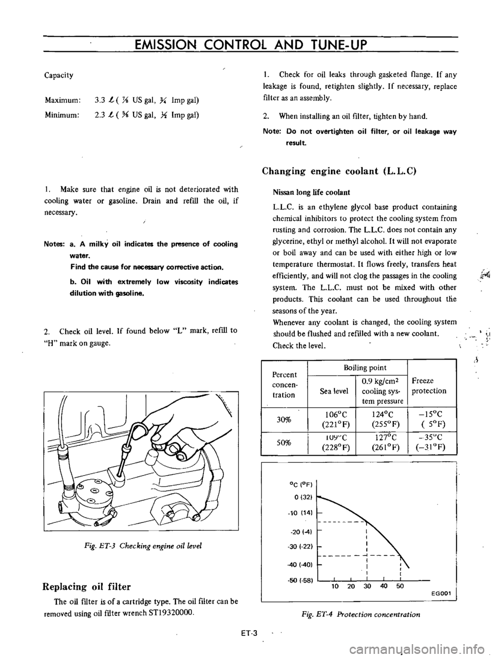
Fig
ET
3
Checking
engine
oil
level
Replacing
oil
filter
The
oil
ftIter
is
of
a
cartridge
type
The
oil
filter
can
be
removed
using
oil
ftIter
wrench
STl9320000
Check
for
oil
leaks
through
gasketed
flange
If
any
leakage
is
found
retighten
slightly
If
necessary
replace
filter
as
an
assembly
2
When
installing
an
oil
filter
tighten
by
hand
Note
Do
not
overtighten
oil
filter
or
oil
leakage
way
result
Changing
engine
coolant
L
L
C
Nissan
long
life
coolant
LLC
is
an
ethylene
glycol
base
product
containing
chemical
inhibitors
to
protect
the
cooling
system
from
rusting
and
corrosion
The
L
L
C
does
not
contain
any
glycerine
ethyl
or
methyl
alcohol
It
will
not
evaporate
or
boil
away
and
can
be
used
with
either
high
or
low
temperature
thermostat
It
flows
freely
transfers
heat
efficiently
and
will
not
clog
the
passages
in
the
cooling
system
The
LL
C
must
not
be
mixed
with
other
products
This
coolant
can
be
used
throughout
tlie
seasons
of
the
year
Whenever
any
coolant
is
changed
the
cooling
system
should
be
flushed
and
refilled
with
a
new
coolant
Check
the
level
J
Percent
Boiling
point
0
9
kgfcm2
Freeze
concen
tration
Sea
level
cooling
sys
protection
tern
pressure
30
1060
C
I
240C
15OC
221OF
255OF
5OF
50
IUY
C
1270C
35
C
2280
F
2610F
3IOF
DC
OF
0
321
10
14
20141
50
58
I
I
I
I
1
I
I
1
30
1
22
40
401
40
10
30
50
20
EGOOl
Fig
ET
4
Protection
concentration
ET
3