Page 99 of 136

Transmission
AUTOMATIC
TRANSMISSION
The
model
3N71B
automatic
transmiSSIOn
IS
a
fully
automatic
Unit
consisting
pnmanly
of
3
element
hydrauhc
torque
converter
and
two
planetary
gear
sets
Two
multiple
disc
clut
ches
a
multiple
disc
brake
a
band
brake
and
a
one
way
sprag
clutch
provide
the
fnctlon
elements
reqUired
to
obtain
the
deSired
fun
tlon
of
the
two
planetary
gear
sets
The
two
planetary
gear
sets
give
three
for
ward
ratIOs
and
one
reverse
Changing
of
the
gear
ratIOs
IS
fully
automatic
In
relation
to
vehicle
speed
and
engine
torque
Input
Vehicle
speed
and
engine
mamfold
vacuum
Signals
are
constantly
fed
to
the
transmiSSIOn
to
prOVide
the
proper
gear
ratIO
for
maximum
effiCiency
and
performance
at
all
throttle
openmgs
The
Model
3N71B
has
SIX
selector
poSitIOns
P
R
N
D
2
1
p
Park
pOSitIOn
posItively
locks
the
out
put
shaft
to
the
transmiSSIOn
case
by
means
of
a
lockmg
pawl
to
prevent
the
vehicle
from
rollmg
either
directIOn
ThiS
pOSitIOn
should
be
selected
whenever
the
dnver
leaves
the
vehicle
The
engme
may
be
started
m
Park
pOSition
R
Reverse
range
enables
the
vehicle
to
be
operated
m
a
reverse
direction
N
Neutral
pOSitIOn
enables
the
engine
to
be
started
and
run
Without
dnvIngthe
vehicle
0
Drive
range
IS
used
for
all
normal
driVing
conditions
Dnve
range
has
three
gear
ratios
from
the
startmg
ratIO
to
direct
dnve
2
2
range
prOVides
performance
for
dnvIng
onshppery
surfaces
2
range
can
also
be
used
for
engine
brakmg
2
range
can
be
selected
at
any
vehicle
speed
and
prevents
the
transmlsslOn
from
shifting
out
of
second
gear
108
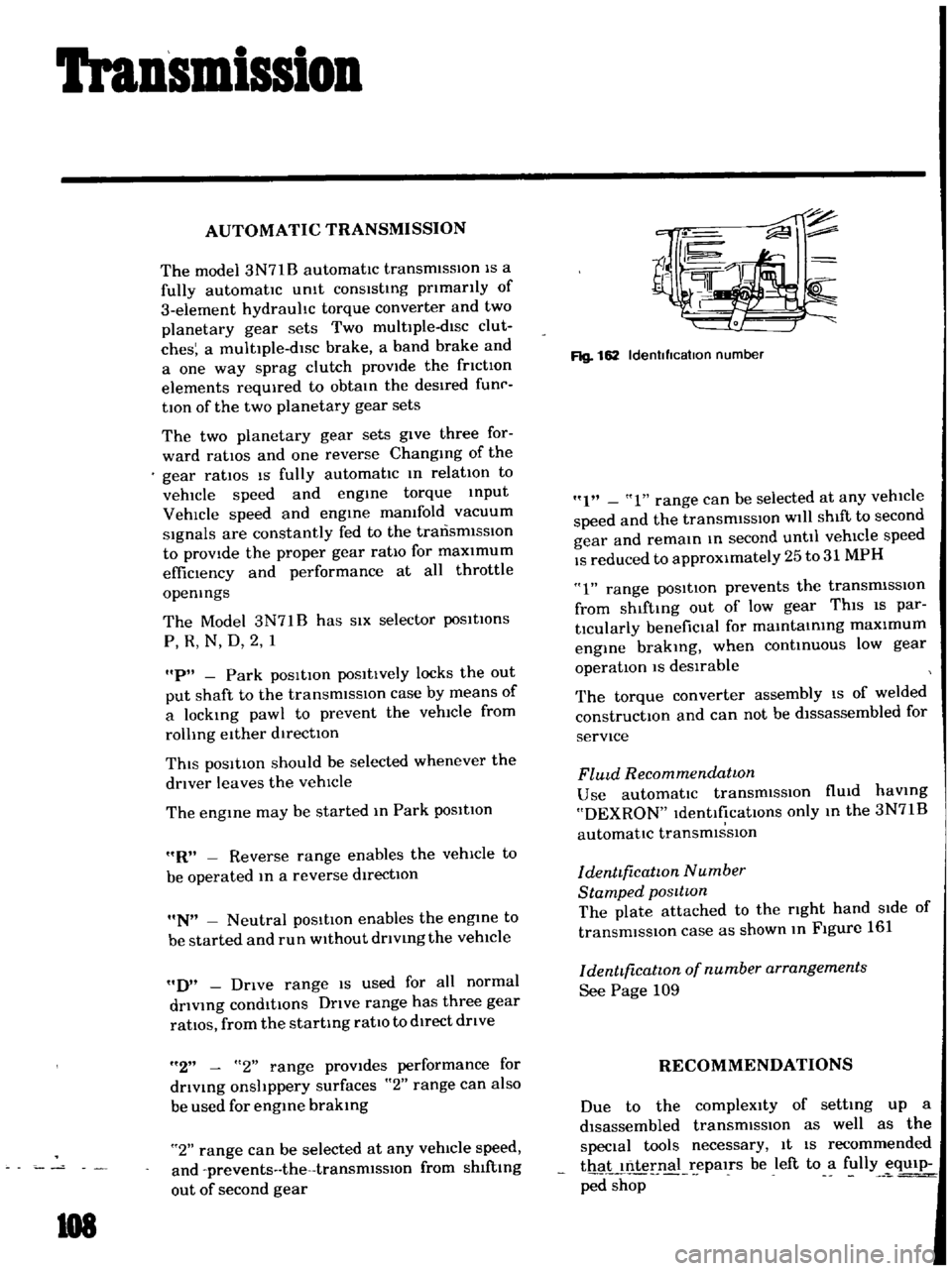
Rg
162
Idenllflcatlon
number
I
1
range
can
be
selected
at
any
vehicle
speed
and
the
transmiSSIOn
will
shift
to
second
gear
and
remain
m
second
until
vehicle
speed
IS
reduced
to
approximately
25
to
31
MPH
1
range
posItion
prevents
the
transmiSSIOn
from
shlftmg
out
of
low
gear
ThiS
IS
par
tlcularly
benefiCial
for
mamtamIng
maximum
engine
brakmg
when
continUOUS
low
gear
operation
IS
deSirable
The
torque
converter
assembly
IS
of
welded
constructIOn
and
can
not
be
dlssassembled
for
service
FlUld
Recommendatwn
Use
automatic
transmiSSIOn
flUid
haVing
DEXRON
IdentificatIOns
only
m
the
3N71B
automatic
transmiSSIOn
denttficatwn
Number
Stamped
posttwn
The
plate
attached
to
the
rIght
hand
Side
of
transmission
case
as
shown
m
Figure
161
denttficatwn
of
number
arrangements
See
Page
109
RECOMMENDATIONS
Due
to
the
compleXity
of
setting
up
a
disassembled
transmissIOn
as
well
as
the
special
tools
necessary
It
IS
recommended
thaL
nternal
epalrs
be
left
to
a
fully
eqUip
ped
shop
Page 116 of 136
II
II
II
II
Oil
pressure
and
ignition
warning
lamps
condition
Oil
pressure
warn
ing
lamp
The
amp
does
not
hght
when
the
19I1ItlOn
sWItch
IS
set
to
ON
II
I
Ptobable
cause
Blown
off
fuse
or
faulty
contact
Broken
lamp
bulb
filament
or
faulty
cable
contact
Defective
oil
pressure
swltch
The
lamp
does
not
Oil
pressure
IS
toO
loW
go
out
wlule
the
engtne
IS
being
operated
Lack
of
engine
oil
Defective
Oil
pressure
sWitch
Il
MethOd
of
tnSpeCtlOn
Check
the
fuse
for
fusing
and
faulty
contact
The
warntng
lamP
does
not
bght
when
oil
pressure
sWitch
yelloW
I
black
cable
15
grounded
The
warntng
lamp
bghts
through
the
above
tnspectlOn
inspect
the
engine
ou
pressure
system
Check
011
level
ConttnUlty
eXists
on
the
oil
pres
sure
sWltch
when
the
engine
IS
belng
operated
o
a
t
a
CorrectIVe
action
Replace
after
COffee
tlng
the
fuse
the
cause
lf
fused
Check
the
hght
bulb
for
burnt
out
fila
ment
and
replace
as
reqUIred
Replace
the
011
pres
Sure
sWitch
Add
oil
Replace
the
01
pres
sure
sWitch
Page 121 of 136
Specifications
SERVICE
DATA
Valve
clearJnce
IHot
mm
In
mm
In
mm
In
kg
Ib
Intdke
exhaust
Fan
belt
tensIOn
Tlghtemng
torque
Cold
Cyhnder
head
bolts
kg
m
ft
Ib
1st
turn
2nd
turn
Re
l1ghtemng
torque
Hot
Mamfold
nuts
Carburetor
nuts
Spark
plugs
ad
capacIty
of
engine
including
od
filter
Maximum
L
US
gal
Imp
gal
L
US
gal
Imp
gal
Mmlmum
Water
capacity
of
coohng
system
Wllhout
heater
L
US
gal
Imp
gal
W
th
heater
L
US
gal
Imp
gal
CompressIOn
pressure
at
rpm
kg
cm2
PSI
Battery
specific
gravity
FrigId
climates
Tropical
clImates
Other
climates
132
Permlsslble
value
rlver
I
22
Over
118
Over
I
20
035
0014
035
0014
10
to
15
0
394
to
0
591
10
22
40
to
4
5
29
to
33
5
5
to
6
0
40
to
43
60
to
6
5
43
to
47
09toI4
65toI0
o
5
to
I
0
3
6
to
7
2
I
5
to
2
0
II
to
14
33
l
2
3
10
42
Ji
49
1
4
IJi
125
to
145
78
to
206
350
Fully
charged
value
at
20
C
68
F
128
123
126
Page 123 of 136
Specifications
ENGINE
GENERAL
SPECIFICATION
Cylinder
Jrrangement
4mlme
Displacement
ce
eu
m
71
71
5
Bore
and
stroke
mm
m
73
x
70
2
874
x
2
756
Valve
arrangement
Over
head
vdlve
Fmng
order
I
3
42
Engine
Idle
rpm
800
Manual
transmiSSIOn
650m
D
Automatic
transrmsslon
Compresc
lon
ratio
85
011
pressure
Hol
al
2
000
rpm
kg
em
Ib
sq
m
3
0
to
3
5
43
10
50
TIGHTENING
TORQUE
Uml
kg
m
ft
Ib
Cyhnder
head
bolts
5
5
10
6
0
40
10
43
3
2
to
3
8
2310
28
CQnnedmg
rod
nuts
Flywheel
bolls
651075
471054
Main
bearing
cap
bolts
5
0
10
6
0
36
to
43
4
0
10
4
8
29
10
35
o
4
to
0
6
2
9
1043
Camshaft
gear
bolts
011
pan
bolts
Ot
pump
bolts
1
I
to
I
7
8
0
10
12
o
9
to
I
4
65
to
lO
J5
to
16
108
to
116
011
stramer
bolts
Crank
pulley
bolts
134