1969 DATSUN B110 engine
[x] Cancel search: enginePage 48 of 136
Fuel
Sptem
Testing
A
fuel
pump
IS
operatIng
properly
when
1tS
pressure
IS
Within
specifications
and
ItS
capacIty
IS
equal
to
the
engine
s
reqUIrements
at
all
speeds
Pressure
and
capacity
must
be
determined
by
two
tests
With
the
pump
mounted
on
the
engIne
Be
sure
that
there
IS
gasohne
m
the
tank
when
conductIng
these
tests
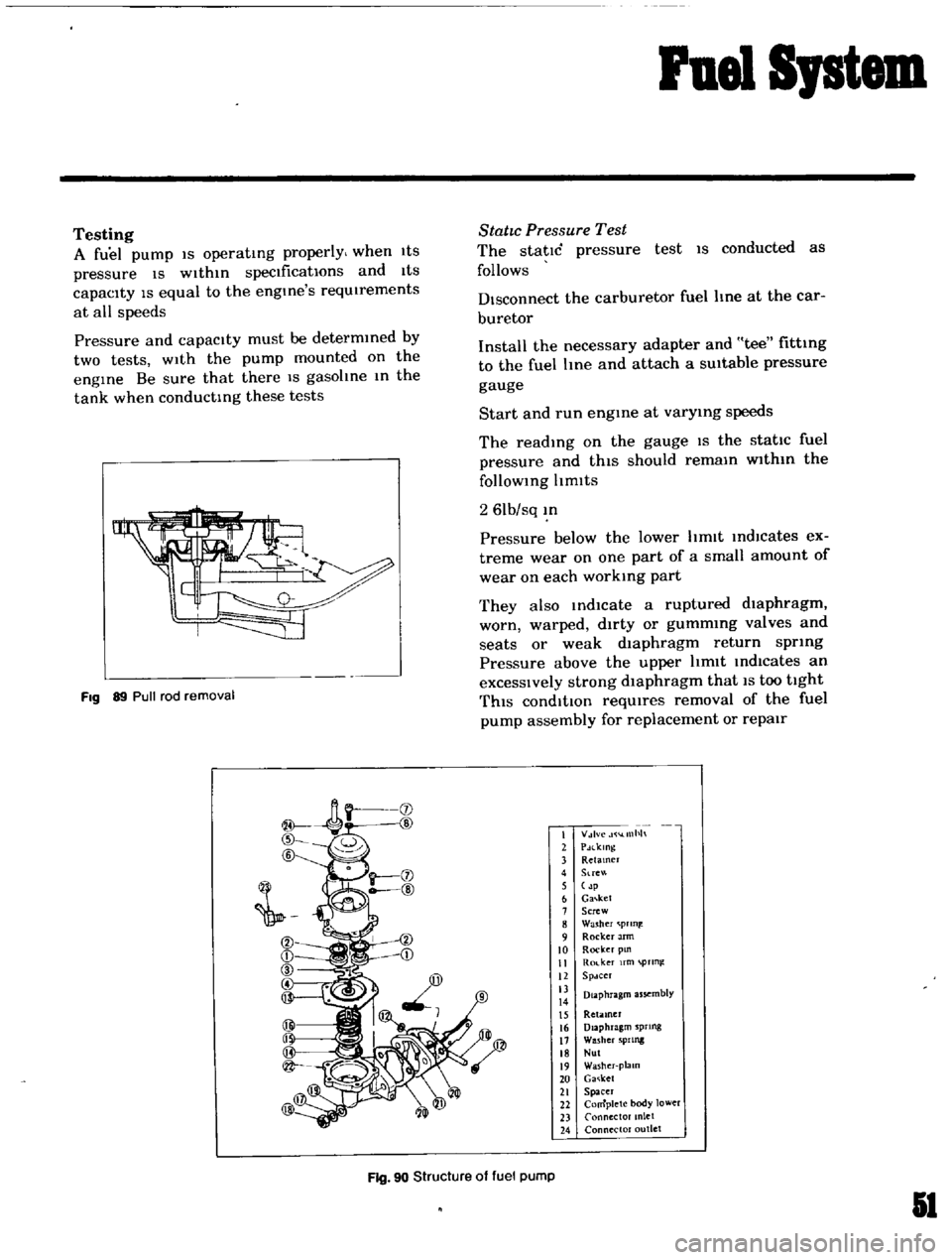
Fig
89
Pull
rod
removal
StatIc
Pressure
Test
The
static
pressure
test
IS
conducted
as
follows
Disconnect
the
carburetor
fuel
line
at
the
car
buretor
Install
the
necessary
adapter
and
tee
fitting
to
the
fuel
Ime
and
attach
a
SUitable
pressure
gauge
Start
and
run
engme
at
varymg
speeds
The
readIng
on
the
gauge
IS
the
static
fuel
pressure
and
thIS
should
remam
wlthm
the
follOWing
Itmlts
2
61b
sq
m
Pressure
below
the
lower
hmlt
IndlCates
ex
treme
wear
on
one
part
of
a
small
amount
of
wear
on
each
working
part
They
also
md1cate
a
ruptured
dIaphragm
worn
warped
dirty
or
gummmg
valves
and
seats
or
weak
dIaphragm
return
spring
Pressure
above
the
upper
hmlt
Indicates
an
excessIVely
strong
dIaphragm
that
IS
too
tight
ThIS
condItIOn
reqUIres
removal
of
the
fuel
pump
assembly
for
replacement
or
repair
I
V
lvc
llllh
2
PdlklOg
3
Retamer
4
Stre
5
p
6
Ga
ket
7
Screw
8
Washer
prln
9
Rocker
Jrm
10
Rocker
pm
II
Ro
ker
fm
pTln
12
Spdcer
13
Diaphragm
assembly
14
15
Retiuner
16
Diaphragm
sprtng
17
Washer
5PIlllg
18
Nul
19
Washer
plalO
20
Ga
ket
21
Spacer
22
Complete
body
lower
23
Connector
anlet
24
Connector
outlet
Fig
90
Structure
of
fuel
pump
51
Page 50 of 136
Fuel
Sptem
The
power
valve
mechanIsm
IS
of
a
vacuum
actuated
boost
type
and
Improves
hIgh
speed
drivIng
The
throttle
opener
control
system
Incor
porates
a
servo
diaphragm
The
servo
dIaphragm
helps
open
the
throttle
valve
at
a
decreasIng
speed
so
as
to
reduce
the
emISSIOn
of
hydrocarbons
to
a
minImum
An
antI
dlesehng
olen01d
IS
used
as
a
means
of
preventIng
dlesehng
When
the
IgnItIOn
key
IS
turned
ofT
the
fuel
passage
Involved
In
the
slow
system
IS
closed
and
the
fuel
supply
IS
shut
down
completely
In
the
chok
mechanIsm
an
electric
automatIc
choke
IS
used
to
automatically
con
trol
the
choke
valve
operatIOn
durIng
the
war
m
up
of
the
engIne
The
carburetor
for
automatic
transmiSSIOn
IS
eqUIpped
WIth
so
called
dash
pot
that
IS
It
makes
smooth
deceleratIng
WIthout
engIne
stall
at
any
operatIng
conditIOn
These
carburetors
are
qUIte
SImIlar
In
ap
pearance
as
explaIned
above
except
the
dash
pot
for
the
automatIc
transmISSion
model
Adjustment
Idhng
Adjustment
Idle
mixture
adjustment
requIres
the
use
of
a
CO
meter
When
prepatlng
to
adjust
Idle
mIxture
It
IS
essentIal
to
have
the
meter
thoroughly
warmed
and
cahbrated
Warm
up
the
engIne
suffiCiently
ContInue
engme
operatIOn
for
one
mmute
un
der
ldhng
speed
Adjust
throttle
adjustIng
screw
so
that
engme
speed
IS
800
rpm
m
N
pos1tIon
for
automatic
transmiSSIOn
Check
IgmtlOn
tl
If
necessary
adjust
It
to
the
speCificatIOns
IgnItIOn
tImlo
800
rpm
Adjust
Idle
adJustmg
screw
so
that
CO
percen
tage
IS
1
5
0
50
at
800
ns
a
On
automatIc
transmiSSIOn
eqUipped
model
check
must
be
done
In
the
D
poSItIon
Be
sure
to
apply
parkmg
brake
and
to
lock
both
front
and
rear
wheels
With
wheel
chocks
b
Hold
brake
pedal
while
steppIng
down
on
accelerator
pedal
OtherWise
car
Will
rush
out
dangerously
On
automatIc
transmiSSIOn
eqUIpped
model
make
sure
that
the
adjustment
has
been
made
With
the
selector
lever
In
N
posItIon
And
then
check
the
specificatIOns
With
the
lever
In
D
pOSitIOn
Insure
that
CO
percent
and
Idle
speed
are
as
follows
Idle
rpm
650
for
Manual
transmISSion
for
Automatic
transmISSion
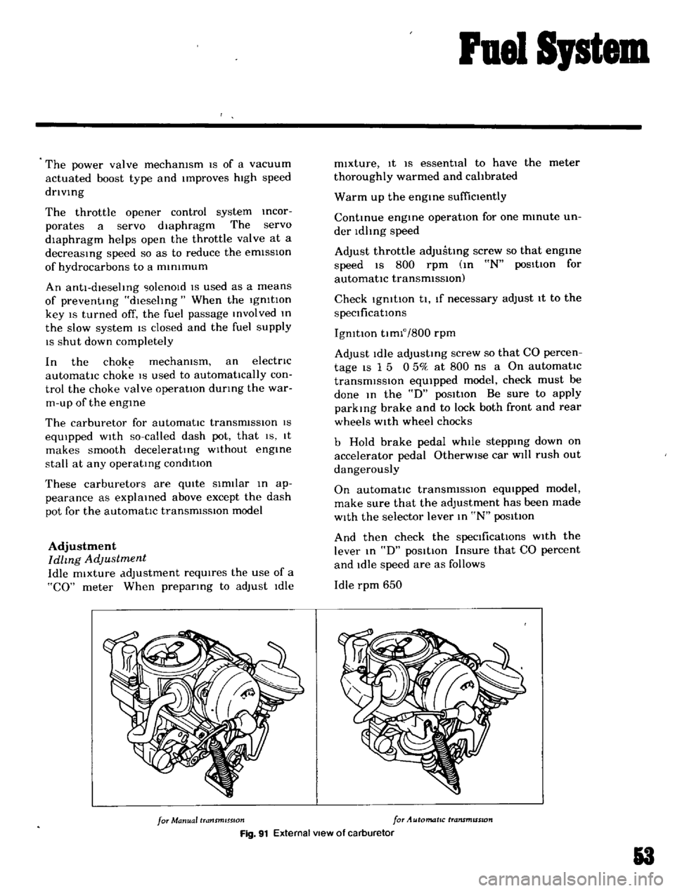
Fig
91
External
view
of
carburetor
3
Page 54 of 136
Fuel
Sptem
ted
on
the
car
If
the
throttle
valve
fails
to
fully
open
the
unIoader
becomes
inoperative
resulting
in
poor
ac
celleration
after
the
engine
is
started
Note
Use
an
accurate
measuring
in
strument
such
as
a
wheatstone
bridge
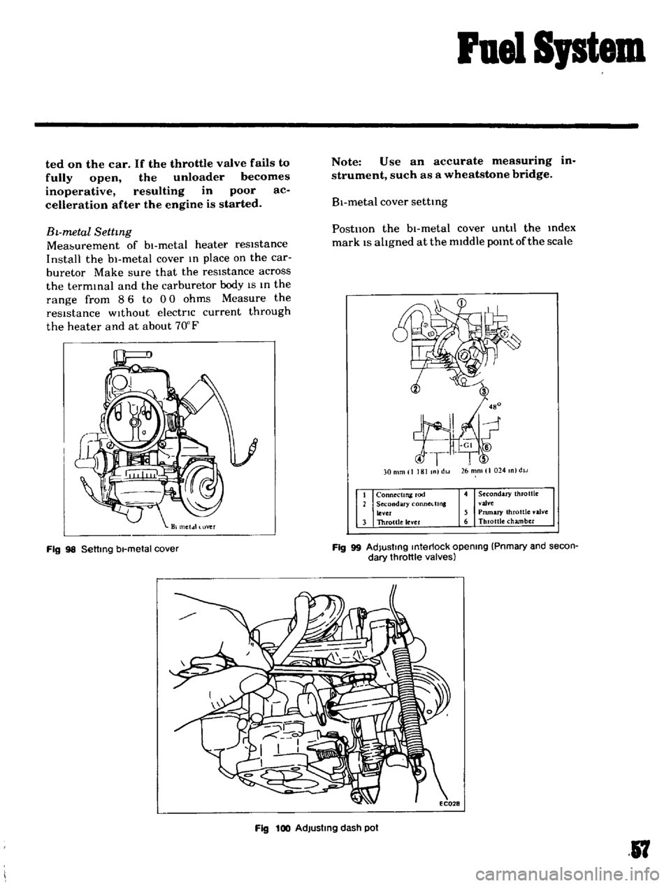
B1
metal
cover
settmg
BL
metal
Settmg
Mea
urement
of
bl
metal
heater
resistance
Install
the
bl
metal
cover
m
place
on
the
car
buretor
Make
sure
that
the
resIstance
across
the
termmal
and
the
carburetor
body
IS
m
the
range
from
8
6
to
0
0
ohms
Measure
the
resIstance
without
electnc
current
through
the
heater
and
at
about
70
F
Postllon
the
bl
metal
cover
until
the
mdex
mark
1S
altgned
at
the
middle
pomt
of
the
scale
26
mm
I
024
m
dlJ
30
m
1
181
In
dlJ
Connectml
rod
Secondary
COnnCl
lms
lever
Throltle
lever
4
Secondary
throttle
vaJve
5
Pnmary
throttle
valve
6
Throttle
chamber
Fig
98
Settmg
bl
metal
cover
Fig
99
AdJustmg
mterlock
opening
Pnmary
and
secon
dary
throttle
valves
Fig
100
AdJustmg
dash
pot
17
Page 55 of 136
ruel
S
stem
Note
When
somewhat
over
choked
set
bl
metal
cover
after
turning
it
clockwise
slightly
Adjustment
oflnterlock
Opelntng
of
Pnmary
and
Secondary
Throttle
Values
Open
the
pnmary
Side
throttle
valve
48
from
the
fully
closed
positIOn
and
measure
clearance
GIn
between
the
throttle
valve
and
throttle
chamber
mSlde
wall
as
shown
m
Figure
99
GIn
0
228
m
WIthout
dlsturbmg
the
above
settmg
bend
connectmg
rod
as
necessary
so
that
secoridary
throttle
valve
IS
about
to
open
Upon
com
pletIOn
of
the
adjustment
make
sure
that
the
hnk
system
operates
smoothly
Dash
Pot
Adjustment
AutomatIC
Trans
mlsszon
car
only
It
IS
necessary
that
the
Idhng
speed
of
engme
and
mIxture
have
been
well
turned
up
and
engme
IS
suffiC1
n
y
warm
1
Turn
throttle
valve
by
hand
and
read
engme
speed
when
the
da
h
pot
Just
touches
the
stop
per
lever
Adjust
the
pOSitIOn
of
the
dash
pot
by
turnmg
the
nut
until
the
engine
speed
IS
In
the
range
from
1
900
to
2
000
rpm
Make
sure
that
the
engine
speed
IS
smoothly
leduced
from
3
000
to
1
000
rpm
within
a
few
econds
Removal
Remove
the
aIr
cleaner
DIsconnect
the
fuel
line
vacuum
line
automatic
choke
harness
and
antl
dlesehng
solenOId
harness
from
carburetor
Remove
the
throttle
lever
Remove
four
nuts
and
washers
retaining
the
carburetor
to
the
mamfold
If
necessary
LIft
the
carburetor
and
remove
from
the
mamfold
Remove
and
dlscard
the
gasketcused
between
the
carburetor
and
mamfold
8
Disassembly
The
main
Jets
and
needle
valves
on
both
primary
and
secondary
Sides
are
accessible
from
outSIde
of
the
carburetor
for
disassem
bly
Remove
throttle
return
sprmg
Remove
pump
level
shaft
take
out
pump
lever
and
pump
connectmg
rod
Remove
rubber
pipe
from
choke
piston
Loosen
off
bolts
secutlng
servo
diaphragm
In
positIOn
take
out
dIaphragm
Back
off
total
of
five
bolts
which
hold
choke
In
posItion
and
remove
rods
of
starter
system
take
out
choke
chamber
In
removmg
chamber
exercise
care
to
aVOId
damaging
float
The
pnmary
and
secondary
emulsIOn
tubes
can
be
disassembled
by
removmg
the
main
air
bleeds
on
the
indiVidual
SIdes
UII
ij
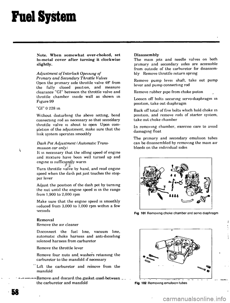
Fig
101
Removmg
choke
chamber
and
servo
diaphragm
o
llQt
o
Fig
102
Removmg
emulsion
tubes
Page 57 of 136
Fuel
SJstem
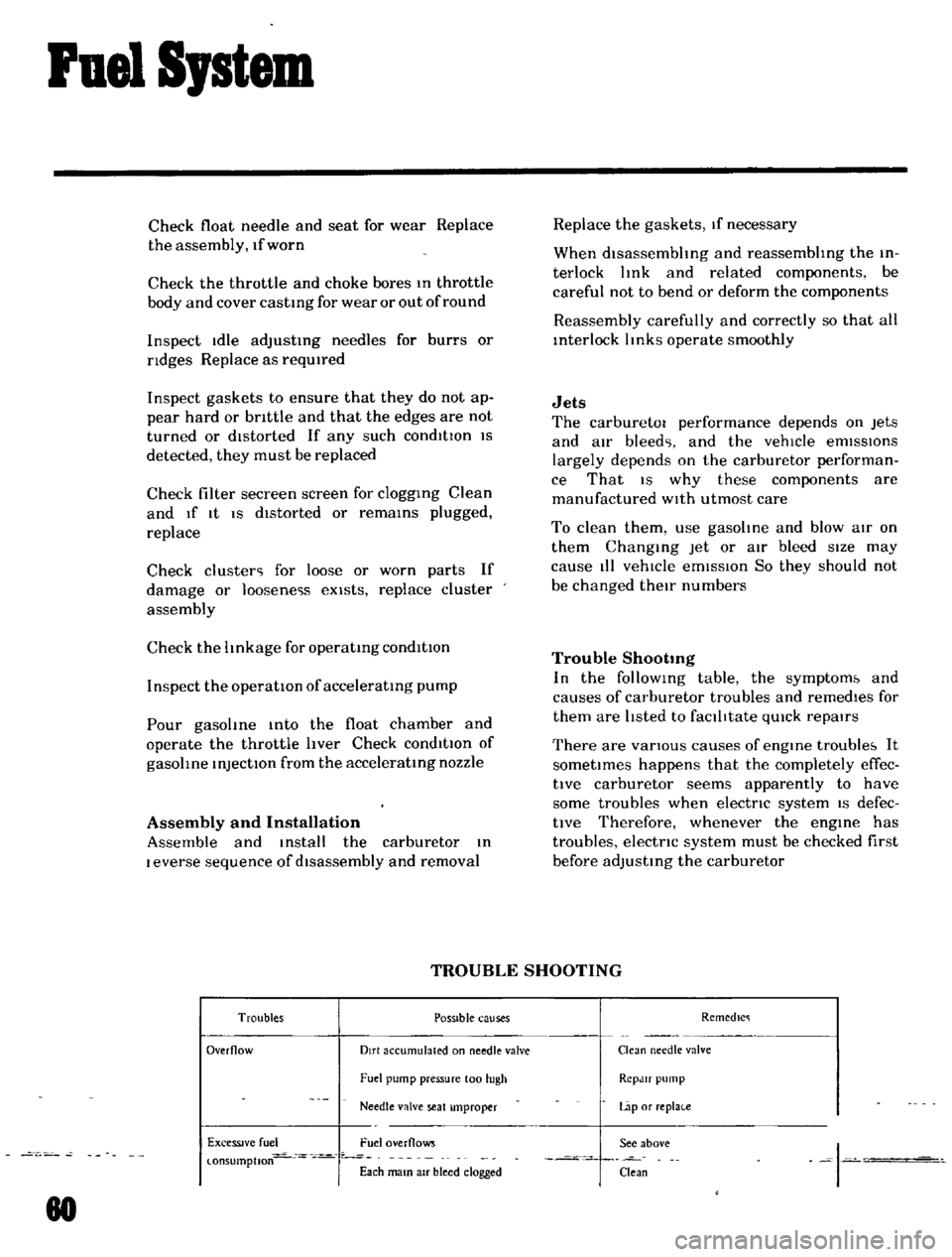
Check
float
needle
and
seat
for
wear
Replace
the
assembly
If
worn
Check
the
throttle
and
choke
bores
In
throttle
body
and
cover
castIng
for
wear
or
out
of
round
Inspect
Idle
adjustIng
needles
for
burrs
or
ndges
Replace
as
reqUIred
Inspect
gaskets
to
ensure
that
they
do
not
ap
pear
hard
or
bnttle
and
that
the
edges
are
not
turned
or
dIstorted
If
any
such
condItIOn
IS
detected
they
must
be
replaced
Check
filter
secreen
screen
for
cloggIng
Clean
and
If
It
IS
dIstorted
or
remaInS
plugged
replace
Check
cluster
for
loose
or
worn
parts
If
damage
or
Ioosene
s
eXists
replace
cluster
assembly
Check
the
hnkage
for
operatIng
condItion
Inspect
the
operatIOn
of
acceleratIng
pump
Pour
gasohne
Into
the
float
chamber
and
operate
the
throttle
hver
Check
conditIOn
of
gasohne
InjectIOn
from
the
acceleratIng
nozzle
Assembly
and
Installation
Assemble
and
Install
the
carburetor
In
I
everse
sequence
of
dIsassembly
and
removal
Replace
the
gaskets
If
necessary
When
dlsassembhng
and
reassembhng
the
In
terlock
hnk
and
related
components
be
careful
not
to
bend
or
deform
the
components
Reassembly
carefully
and
correctly
so
that
all
Interlock
hnks
operate
smoothly
Jets
The
carburetor
performance
depends
on
Jets
and
aIr
bleed
and
the
vehicle
emISSIOns
largely
depends
on
the
carburetor
performan
ce
That
IS
why
these
components
are
manufactured
WIth
utmost
care
To
clean
them
use
gasohne
and
blow
aIr
on
them
ChangIng
Jet
or
air
bleed
sIze
may
cause
III
vehICle
emIssIon
So
they
should
not
be
changed
theIr
numbers
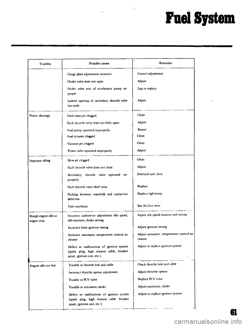
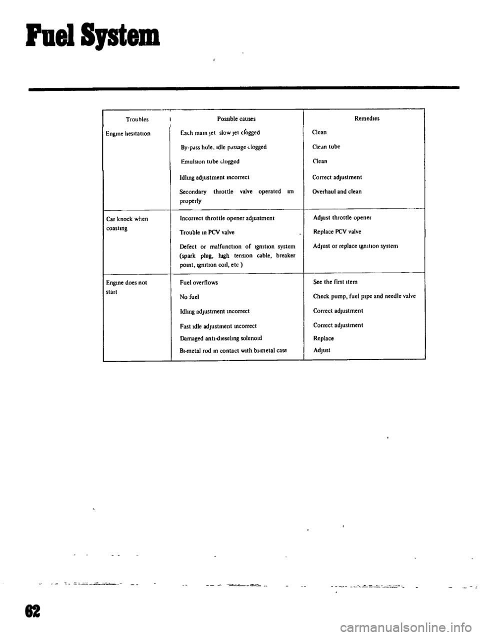
Trouble
Shootmg
In
the
follOWIng
table
the
symptom
and
causes
of
carburetor
troubles
and
remedIes
for
them
are
hsted
to
faclhtate
qUIck
repaIrs
There
are
vanous
causes
of
engIne
trouble
It
sometImes
happens
that
the
completely
effec
tlve
carburetor
seems
apparently
to
have
some
troubles
when
electnc
systern
IS
defec
tIve
Therefore
whenever
the
engIne
has
troubles
electnc
system
must
be
checked
first
before
adjusting
the
carburetor
TROUBLE
SHOOTING
Troubles
POSSible
causes
Remedlc
Overflow
Dirt
accumulated
on
needle
valve
Clean
needle
valve
Fuel
pump
pressure
100
hIgh
RCpJlf
pump
Needle
valve
seat
Improper
Lap
or
replai
e
ExceSSIve
fuel
Fuel
overflows
See
above
I
l
onsumptlon
Each
mam
aIr
bleed
clogged
Clean
80
Page 58 of 136
ruel
Sptem
Troubles
Power
shortage
Improper
IdlIng
Rough
engIne
Idle
or
eogme
stop
Engme
Idle
too
fast
Possible
causes
Gauge
plate
adjustment
mcorrect
Choke
valve
does
not
open
Outlet
valve
seat
of
accelerator
pump
1m
proper
Lmked
openmg
of
secondary
throttle
valve
too
early
each
mam
Jet
clogged
EaLh
throttle
valve
does
not
fully
open
Fuel
pump
operated
Improperly
uel
stramer
clogged
Vacuum
Jet
clogged
Power
vdlve
operated
Improperly
Slow
Jel
dugged
Fat
h
thronle
valve
does
not
close
Secondary
throttle
valve
operated
Im
properly
Eal
h
throttle
valve
shaft
wear
Packing
between
mamfold
and
carburetor
defective
Fuel
overflows
Incorrect
carburetor
adjustment
Idle
speed
Idle
miXture
choke
settmg
Incorrect
baSIC
1
OIt100
tunmg
Incorrect
automatic
temperature
control
air
cleaner
Defect
or
malfunction
of
Igmtlon
system
spark
plug
lugh
tenSion
cable
breaker
JX
Int
Ignition
COIl
etc
Trouble
In
throttle
lInk
and
cable
Incorred
throttle
opener
adjustment
Trouble
In
PCV
valve
Trouble
In
automatic
choke
Defect
or
malfunctIOn
of
Igmhon
s
stem
spark
plug
hIgh
tenSion
cable
breaker
pomt
Ignition
Call
elc
Remedies
Correct
adjustment
Adjust
Lap
or
replace
Adlust
Clean
Adjust
Repair
Clean
Clean
Adlust
Clean
Adlusl
Overhaul
and
dedn
Replace
ReplaLe
tlghtenlllg
See
the
fust
Item
Adjust
Idle
speed
mixture
dnd
tUllIng
Adjust
19mtlon
timing
Adjust
automatlL
temperature
control
air
cleaner
Adjust
or
replaLe
IgllltIun
system
Chel
k
throttle
hnk
and
Lable
Adjust
throttle
opener
Replace
PCV
vJlve
Adjust
auotmJtIL
l
hoke
Adjust
or
replac
e
IgllltIun
system
J
81
Page 59 of 136
Fuel
I
em
Troubles
Engine
hesitatIOn
Car
knock
when
coastIng
EnglOe
does
not
start
82
POSSIble
causes
Eal
h
mam
Jet
slow
Jet
clogged
By
pdss
hole
die
pdssage
dogged
Emulsion
lube
dogged
Idhng
adlostment
mcorrect
Secondary
throttle
valve
operated
1m
properly
Incorrect
throttle
opener
adjustment
Trouble
m
PCV
valve
Defect
or
malfunction
of
Igmtlon
system
spark
plog
ugh
tenSIon
cable
breaker
pomt
IgmtIon
cod
etc
Fuel
overflows
No
fuel
IdlIng
adjustment
mearrect
Fast
Idle
adjustment
mcareeet
Damaged
antl
dlesehng
solenoId
BI
metal
rod
m
contact
WIth
bl
metal
case
RemedIes
Clean
Cledn
lube
lean
Correct
adjustment
Overhaul
and
clean
AdjUstlhroltle
opener
Replace
PCV
valve
Adjust
or
replace
IgJuhan
system
See
the
first
Item
Check
pump
fuel
pIpe
and
needle
valve
Correct
adjustment
Correct
adjustment
Replace
Adlust
Page 97 of 136
Transmission
Worn
gears
shaft
and
or
heanng
Repl
ll
c
In
ufficlcnt
operatmg
stroke
due
to
worn
or
loose
shdmg
pdll
Repair
or
replal
c
Defective
or
damaged
synchronIzer
Replace
Gear
slips
out
of
mesh
In
the
most
cases
thiS
trouble
occurs
when
the
Interlock
plunger
check
ball
and
or
spnng
IS
worn
or
weakened
or
when
the
control
system
IS
defectIve
In
thiS
Cd
the
trouble
cannot
be
corrected
by
repldtlllg
gt
drs
and
therefore
trouble
shootmg
must
be
earned
out
carefully
It
should
also
be
noted
that
gear
slips
out
of
mesh
due
to
vlbralIon
generated
by
weakened
front
and
rear
engme
mounts
Worn
mterlock
plunger
Replal
c
Worn
check
hall
and
or
weakened
or
broken
sprmg
Replal
c
Worn
fork
rod
ball
groove
RepI
H
e
Worn
or
damaged
beanng
Repldce
Worn
or
damaged
gear
Repldl
c
NOise
When
nOIse
occurs
unoer
engine
Idling
and
stops
whde
the
clutch
IS
dlseng
lged
or
when
nOI
Olcurs
while
shlftmg
gears
It
may
Judged
that
the
nOIse
IS
from
the
tranSmll
lSIUn
Ino
ufllclenl
or
1mproper
lubncant
Add
od
or
replace
With
deSignated
oIl
Ollleaklllg
due
to
defectIve
011
seal
md
gasket
clogged
breather
etc
Clean
or
replace
Worn
beanng
High
hummmg
occurs
at
a
high
speed
Replace
Damaged
beanng
Cychc
knockmg
sound
occurs
alllo
at
a
low
speed
Replace
Worn
each
sphne
Replace
Worn
each
hushmg
Replace
108