1969 DATSUN B110 engine
[x] Cancel search: enginePage 15 of 136
Bngine
WIres
for
accelerator
and
choke
The
operatIOn
Will
be
carned
out
more
easily
by
removing
the
a1r
cleaner
Lift
up
the
engine
toward
the
front
INST
ALLA
TION
Install
the
engine
In
reverse
sequence
of
removal
Disconnecting
clutch
wire
on
nght
hand
dnve
model
On
left
hand
dnve
model
disconnect
hydraulIc
line
from
the
clutch
slave
cylInder
DIsconnect
the
clutch
WIre
at
the
JXlrtlOn
of
the
wIthdrawal
lever
Remove
the
exhaust
front
tube
Disconnect
the
the
cable
to
the
back
up
lamp
SWItch
D1sconnect
the
speedometer
cable
Remove
the
propeller
shaft
Remove
four
bolts
used
In
the
differential
carner
SIde
and
Withdraw
the
propeller
shaft
Remove
the
shift
lever
Model
With
remote
control
shIft
lever
Disconnect
the
remote
control
rod
at
the
JXlr
tlOn
of
transmiSSIOn
outer
lever
and
remove
the
remote
control
rod
Model
With
floor
Sh1ft
lever
Remove
the
boot
WIthdraw
the
lock
pin
and
remove
the
lever
The
operatIOn
IS
carned
out
In
the
passenger
compartment
Model
With
automatic
transmiSSIOn
Remove
pinS
from
both
ends
of
the
cross
shaft
and
remove
the
shIft
rod
Suspend
the
engine
With
wire
Remove
the
front
engine
mounting
installation
nuts
Remove
the
rear
engine
mounting
installation
nuts
When
removing
the
engine
mounting
in
stallation
nuts
be
sure
to
apply
a
Jack
beneath
the
transmiSSIOn
CLEANING
AND
INSPECTION
Clean
the
engine
thoroughly
before
disassem
bly
Before
cleaning
the
engine
remove
the
l
electncal
parts
and
plug
up
the
carburetor
air
horn
to
aVOid
intrusIOn
of
foreign
matter
The
engine
extenor
Check
the
covers
and
bolts
for
breakage
rust
damage
and
loss
CylInder
block
Check
thoroughly
the
water
Jacket
for
cracks
and
breakage
Clutch
hOUSing
Check
for
cracks
011
pan
Check
for
excessive
rust
DISASSEMBLY
Mount
engine
assembly
on
engine
stand
Remove
the
engine
mounting
bracket
R
H
Side
Install
the
engine
attachment
Mount
the
engine
on
the
stand
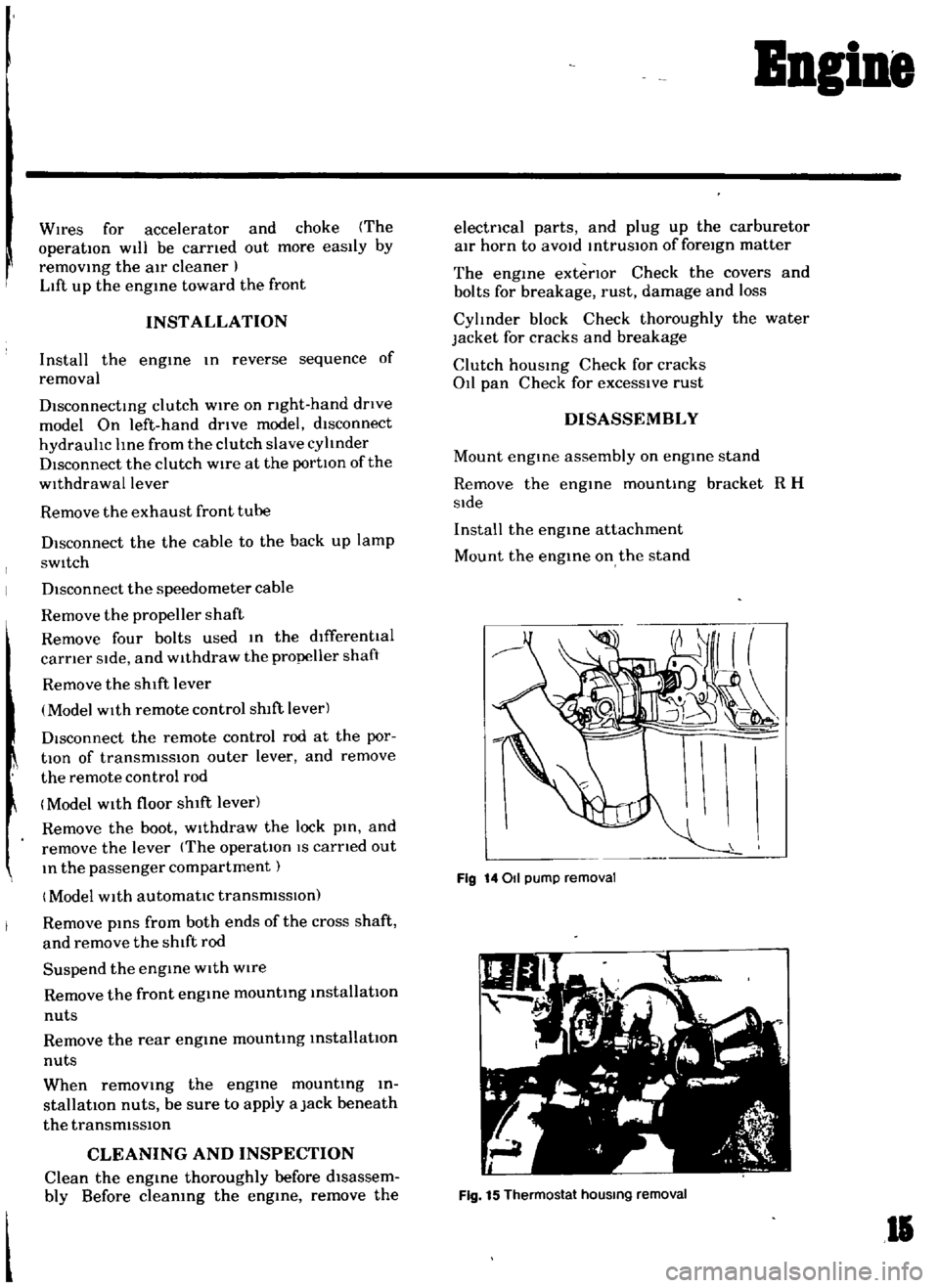
Fig
14011
pump
removal
Fig
15
Thermostat
hOUSing
removal
II
Page 16 of 136
Bngine
Remove
the
altel
nator
and
engine
mounting
bracket
L
H
slde
Remove
the
crankshaft
pulley
Remove
the
011
pump
together
With
the
011
filtel
Remove
the
high
tensIOn
cable
wIth
the
dlstnbutor
cap
on
Remove
the
spark
plugs
Remove
the
dlstllbutor
assembly
Remove
the
carburetor
Remove
the
rocker
cover
Remove
the
thermo
itat
houslllg
Remove
the
manifolds
Remove
the
water
pump
Remove
the
fuel
pump
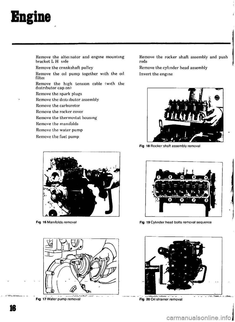
Fig
16
Manifolds
removal
Fig
17
Water
pump
removal
18
Remove
the
rocker
shaft
assembly
and
push
rods
Remove
the
cylInder
head
assembly
Invert
the
engine
Fig
18
Rocker
shaft
assembly
removal
7
1
l
I
h
Y
r
I
w
L
1
Fig
19
Cylinder
head
bolts
removal
sequence
o
Fig
20
011
strainer
removal
j
Page 17 of 136
Bneine
Remove
the
011
pan
and
011
straIner
Remove
the
tImIng
chaIn
cover
and
the
chaIn
tenSlOner
Remove
the
crankshaft
and
camshaft
sprockets
together
WIth
the
timing
chaIn
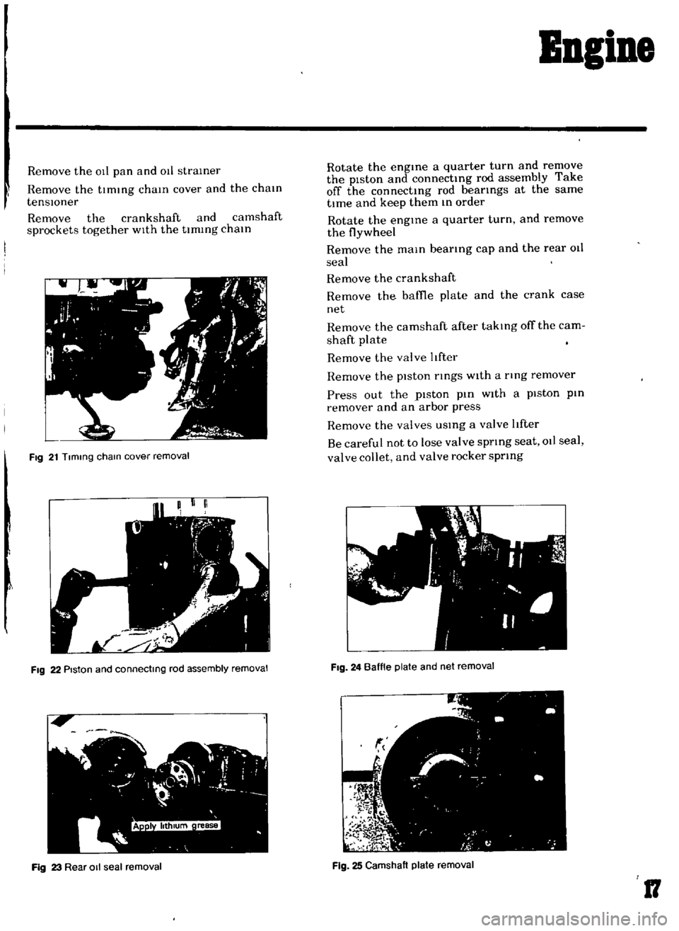
Fig
21
Tlmmg
cham
cover
removal
I
FIg
22
PIston
and
connectmg
rod
assembly
removal
Fig
23
Rear
011
seal
removal
Rotate
the
engIne
a
quarter
turn
and
remove
the
piston
and
connectIng
rod
assembly
Take
off
the
connectIng
rod
beatings
at
the
same
tIme
and
keep
them
In
order
Rotate
the
engIne
a
quarter
turn
and
remove
the
flywheel
Remove
the
maIn
bearIng
cap
and
the
rear
011
seal
Remove
the
crankshaft
Remove
the
baffie
plate
and
the
crank
case
net
Remove
the
camshaft
after
takIng
off
the
cam
shaft
plate
Remove
the
valve
tfter
Remove
the
piston
rIngs
With
a
tlng
remover
Press
out
the
piston
pIn
With
a
piston
pin
remover
and
an
arbor
press
Remove
the
valves
USIng
a
valve
tfter
Be
careful
not
to
lose
valve
sprIng
seat
011
seal
valve
collet
and
valve
rocker
sprIng
FIg
24
Baffle
plate
and
net
removal
Fig
25
Camshaft
plate
removal
17
Page 26 of 136
BDgiDe
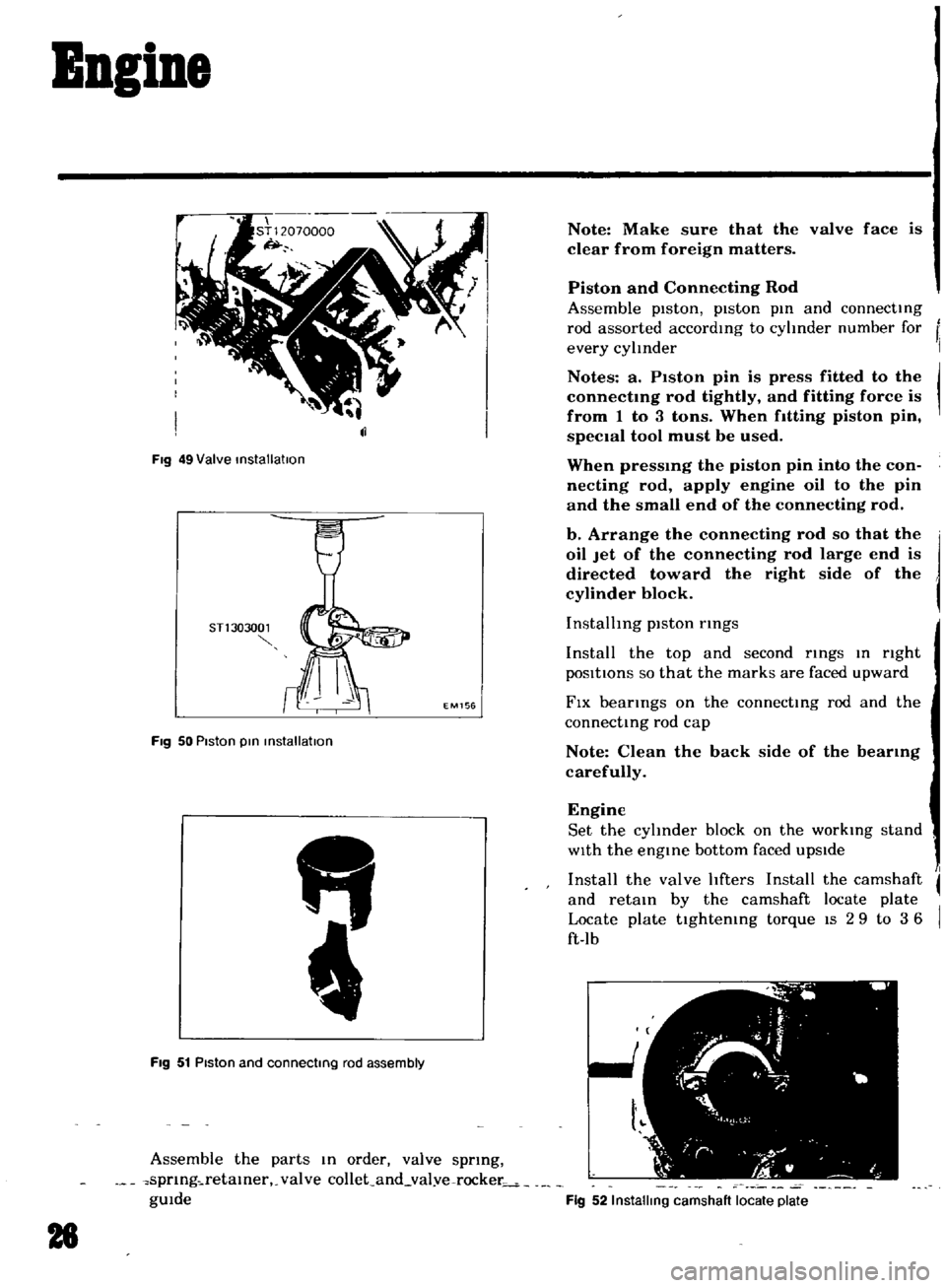
Fig
49
Valve
installatIon
STl
303001
EM156
Fig
50
Piston
pin
installation
FIg
51
Piston
and
connecting
rod
assembly
Assemble
the
parts
In
order
valve
sprmg
spnng
retamer
valve
collet
and
val
ve
rocker
gUIde
28
Note
Make
sure
that
the
valve
face
is
clear
from
foreign
matters
Piston
and
Connecting
Rod
Assemble
pIston
piston
pm
and
connecting
rod
assorted
accordmg
to
cyhnder
number
for
every
cylInder
Notes
a
P1ston
pin
is
press
fitted
to
the
connectmg
rod
tightly
and
fitting
force
is
from
1
to
3
tons
When
fitting
piston
pin
speCIal
tool
must
be
used
When
pressmg
the
piston
pin
into
the
con
necting
rod
apply
engine
oil
to
the
pin
and
the
small
end
of
the
connecting
rod
b
Arrange
the
connecting
rod
so
that
the
oil
Jet
of
the
connecting
rod
large
end
is
directed
toward
the
right
side
of
the
cylinder
block
InstallIng
piston
rmgs
Install
the
top
and
second
rings
In
nght
pOSItIOns
so
that
the
marks
are
faced
upward
FIX
bearings
on
the
connecting
rod
and
the
connecting
rod
cap
Note
Clean
the
back
side
of
the
bearmg
carefully
Engine
Set
the
cyhnder
block
on
the
workmg
stand
WIth
the
engine
bottom
faced
upSIde
Install
the
valve
hfters
Install
the
camshaft
and
retain
by
the
camshaft
locate
plate
Locate
plate
tightemng
torque
IS
2
9
to
3
6
ft
lb
Fig
52
Installing
camshaft
locate
plate
Page 27 of 136
Bogine
Note
Set
the
locate
plate
so
as
the
LOWER
mark
comes
to
the
engine
bot
tom
side
Set
the
maIn
bearIngR
on
theIr
posItIOns
on
the
cylinder
block
Notes
a
The
center
bearmg
No
3
bearmg
is
a
flanged
type
for
thrust
force
b
Two
lOner
bearmgs
No
2
and
No
4
are
of
the
same
type
c
The
front
bearmg
No
1
IS
the
same
type
as
the
rear
bearmg
No
5
d
All
bearings
except
for
No
I
bearing
are
interchangeable
between
upper
and
lower
bearings
Apply
engIne
OIl
to
the
mam
bearIng
surfaces
on
both
sIdes
of
the
cyltnder
block
and
cap
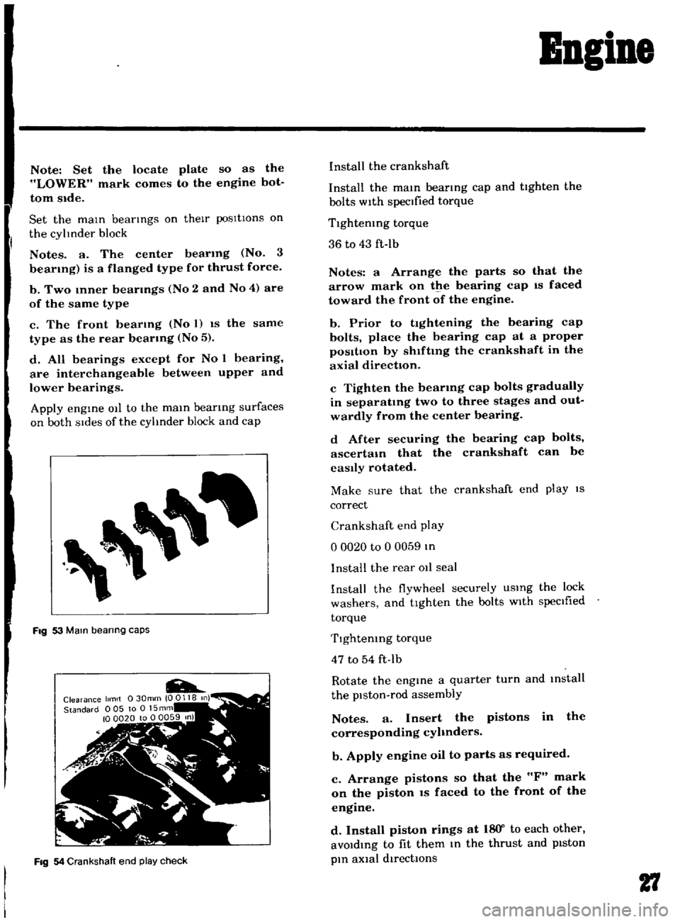
Fig
53
Mam
bearing
caps
Fig
54
Crankshaft
end
play
check
Install
the
crankshaft
Install
the
mam
bearmg
cap
and
tighten
the
bolts
with
specified
torque
Tlghtemng
torque
36
to
43
ft
Ib
Notes
a
Arrange
the
parts
so
that
the
arrow
mark
on
the
bearing
cap
IS
faced
toward
the
front
of
the
engine
b
Prior
to
tightening
the
bearing
cap
bolts
place
the
bearing
cap
at
a
proper
posItIon
by
shlftmg
the
crankshaft
in
the
axial
direction
c
Tighten
the
bearmg
cap
bolts
gradually
in
separatmg
two
to
three
stages
and
out
wardly
from
the
center
bearing
d
After
securing
the
bearing
cap
bolts
ascertam
that
the
crankshaft
can
be
easily
rotated
Make
sure
that
the
crankshaft
end
play
IS
correct
Crankshaft
end
play
o
0020
to
0
0059
In
I
nstalI
the
rear
011
seal
Install
the
flywheel
securely
USIng
the
lock
washers
and
tighten
the
bolts
with
specIfied
torque
Tlghtemng
torque
47
to
54
ft
Ib
Rotate
the
engine
a
quarter
turn
and
mstall
the
piston
rod
assembly
Notes
a
Insert
the
pistons
in
the
corresponding
cyhnders
b
Apply
engine
oil
to
parts
as
required
c
Arrange
pistons
so
that
the
F
mark
on
the
piston
IS
faced
to
the
front
of
the
engine
d
Install
piston
rings
at
18
Y
to
each
other
avoIdIng
to
fit
them
In
the
thrust
and
pIston
pIn
aXial
directIOns
27
Page 30 of 136
BDgiDe
Install
the
new
011
seal
to
the
front
cover
The
front
cover
011
seal
should
be
replaced
when
the
front
cover
IS
disassembled
Install
the
front
cover
applYing
the
seahng
agent
to
both
surfaces
of
the
gasket
Tlghtemng
torque
36
to
5
1
ft
lb
Install
the
ot
strainer
and
the
011
pan
uSing
the
gasket
Apply
seahng
agent
on
both
surfaces
of
the
gasket
especIally
on
the
front
and
rear
por
tlOns
of
the
011
pan
011
pan
tlghtemng
torque
2
9
to
4
3
ft
lb
Invert
the
engine
and
Install
the
cyhnder
head
assembly
and
gasket
Note
Apply
sealing
agent
overall
the
cylinder
block
surface
Place
the
gasket
on
It
and
apply
sealing
agent
to
the
gasket
top
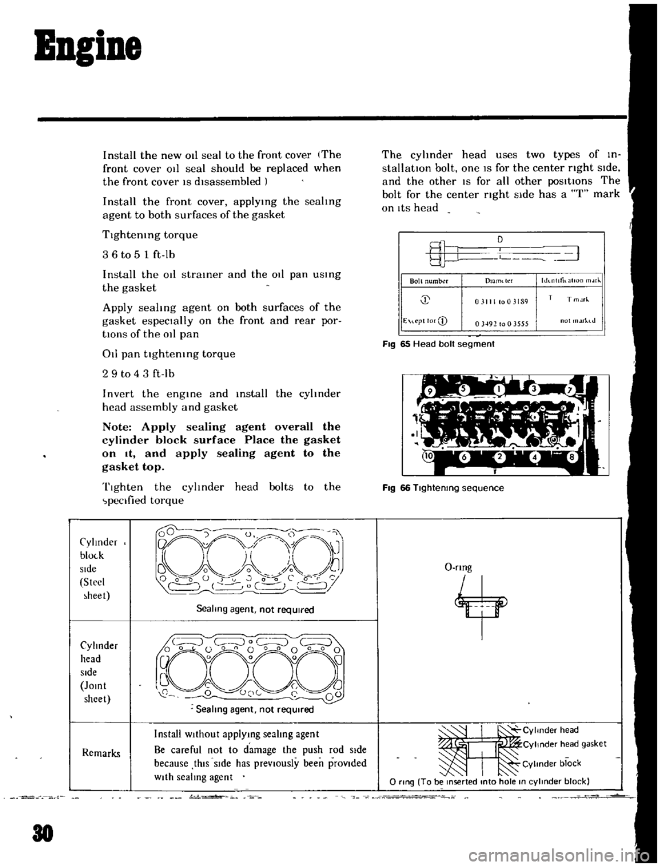
Tighten
the
cylinder
head
bolts
to
the
peclfied
torque
Cylmder
bloLk
Side
Stecl
heet
Sealmg
agent
not
required
Cylinder
head
Side
Jomt
sheet
Remarks
Install
WIthout
applymg
sealing
agent
Be
careful
not
to
damage
the
push
rod
Side
because
thIS
SIde
has
prevIOusly
been
provIded
WIth
sealing
agent
J
30
v
o
The
cyhnder
head
uses
two
types
of
in
stallatIOn
bolt
one
IS
for
the
center
nght
SIde
and
the
other
IS
for
all
other
posItIOns
The
bolt
for
the
center
nght
Side
has
a
I
mark
on
ItS
head
L
1
Bolt
number
hh
nlltilatlOn
rJ
Dlaml
tl
f
j
031111003189
T
T
1M
E
u
pt
lor
CD
03492
to
0
3555
ot
rhJ
FIg
65
Head
bolt
segment
Fig
66
Tlghtenmg
sequence
O
rmg
4
ItI
CYlmder
head
Cylinder
h
ad
gasket
Cylinder
block
o
rtng
To
be
mserted
mto
hole
m
cylmder
block
Page 32 of 136
BBgiBe
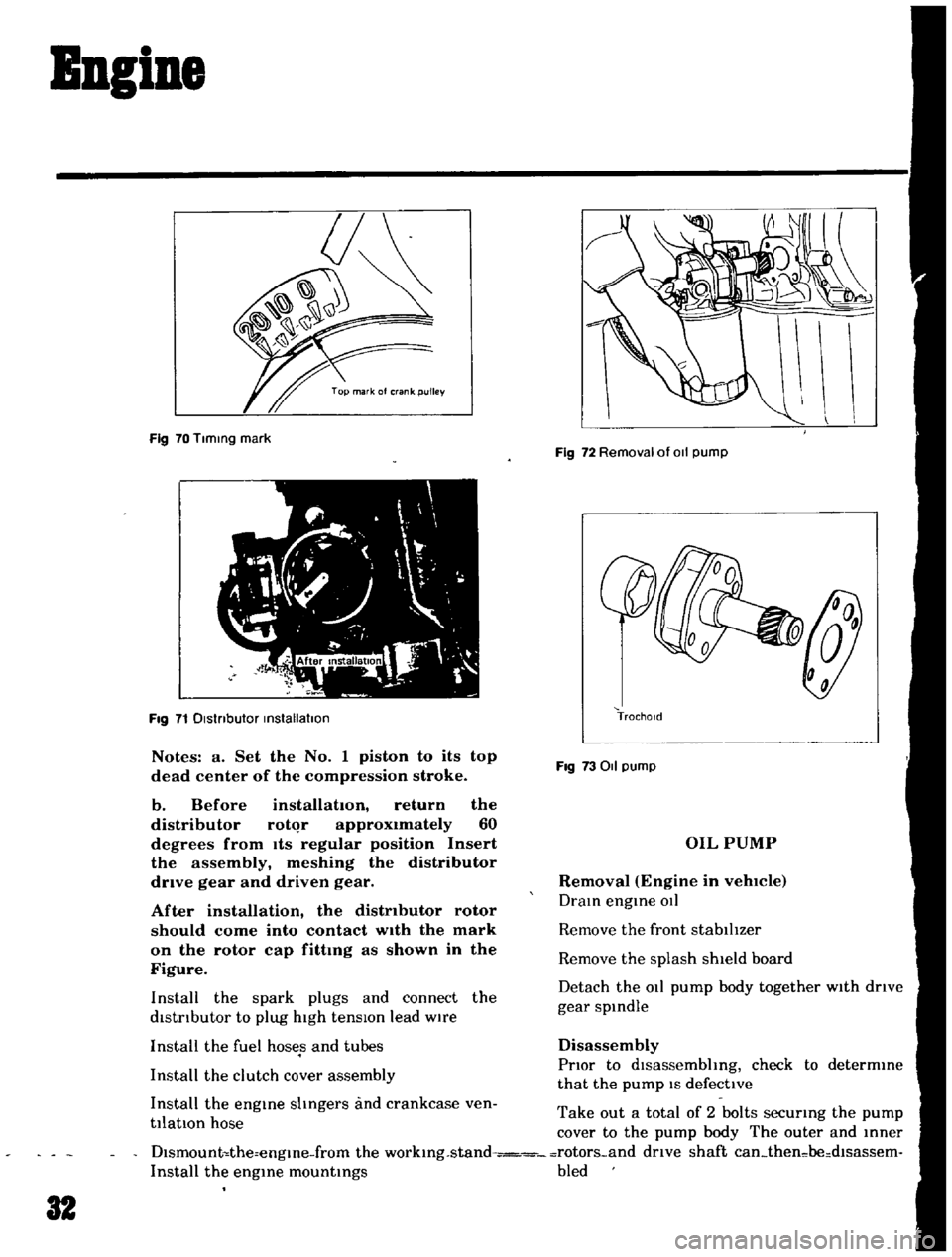
Fig
70
Tlmmg
mark
Fig
71
Dlstnbutor
mstallatlon
Notes
a
Set
the
No
1
piston
to
its
top
dead
center
of
the
compression
stroke
b
Before
installation
return
the
distributor
rotqr
approximately
60
degrees
from
Its
regular
position
Insert
the
assembly
meshing
the
distributor
drive
gear
and
driven
gear
After
installation
the
distributor
rotor
should
come
into
contact
wIth
the
mark
on
the
rotor
cap
fittmg
as
shown
in
the
Figure
Install
the
spark
plugs
and
connect
the
distrIbutor
to
plug
high
tensIOn
lead
wire
Install
the
fuel
hoses
and
tubes
Install
the
clutch
cover
assembly
Install
the
engme
shngers
and
crankcase
ven
tilatIOn
hose
Fig
72
Removal
of
011
pump
TrochoId
Fig
73011
pump
OIL
PUMP
Removal
Engine
in
vehlCIe
Dram
engme
OIl
Remove
the
front
stabilIzer
Remove
the
splash
shield
board
Detach
the
011
pump
body
together
with
drIve
gear
spmdle
Disassembly
PrIor
to
dlsassembhng
check
to
determme
that
the
pump
IS
defective
Take
out
a
total
of
2
bolts
securmg
the
pump
cover
to
the
pump
body
The
outer
and
mner
Dlsmount
the
engme
from
the
workmg
stand
rotors
and
drive
shaft
can
then
be
dlsassem
Install
the
engme
mountmgs
bled
32
Page 47 of 136
ruel
Sptem
FUEL
FILTER
DESCRIPTION
The
fuel
filter
IS
of
a
cartndge
type
It
uses
paper
element
as
traIner
element
which
can
be
checked
for
condItIOn
from
outsIde
ThIS
filter
cannot
be
cleaned
Replace
the
filter
at
the
peclfied
servICe
Interval
01
If
It
becomes
clogged
or
I
estncted
REMOVAL
DIsconnect
Inlet
and
outlet
fuel
hnes
from
fuel
filter
and
remove
fuel
filter
if
EF005
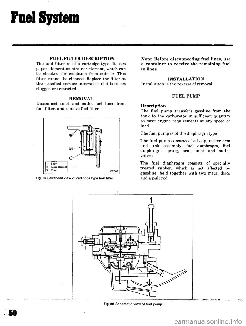
Fig
87
Sectional
view
of
cartridge
type
fuel
filter
Note
Before
disconnecting
fuel
lines
use
a
container
to
receive
the
remaining
fuel
In
lines
INSTALLATION
InstallatIOn
IS
the
reverse
of
removal
FUEL
PUMP
Description
The
fuel
pump
transfers
gasoline
from
the
tank
to
the
carburetor
In
suffiCient
quantity
to
meet
engine
requIrements
at
any
speed
or
load
The
fuel
pump
IS
of
the
diaphragm
type
The
fuel
pump
conSIsts
of
a
body
rocker
arm
and
link
assembly
fuel
diaphragm
fuel
diaphragm
spnng
seal
Inlet
and
outlet
valves
The
fuel
diaphragm
consists
of
specially
treated
rubber
whIch
IS
not
affected
by
gasohne
held
together
WIth
two
metal
diSCS
and
a
pull
rod
t
Fig
88
SchematiC
view
of
fuel
pump
R
0