1900 MITSUBISHI DIAMANTE boot
[x] Cancel search: bootPage 338 of 408
9-2 BRAKES
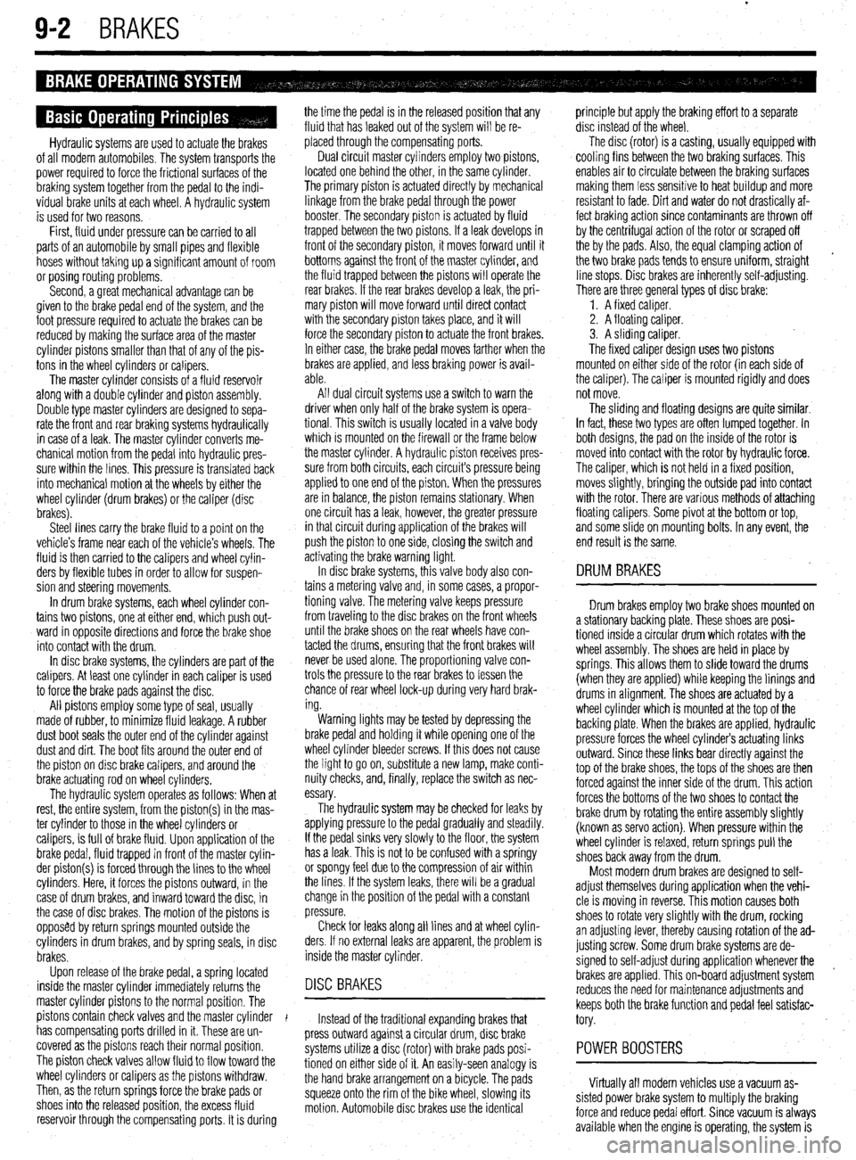
Hydraulic systems are used to actuate the brakes
of all modern automobiles. The system transports the
power required to force the frictional surfaces of the
braking system together from the pedal to the indi-
vidual brake units at each wheel. A hydraulic system
is used for two reasons.
First, fluid under pressure can be carried to all
parts of an automobile by small pipes and flexible
hoses without taking up a significant amount of room
or posing routing problems.
Second, a great mechanical advantage can be
given to the brake pedal end of the system, and the
foot pressure required to actuate the brakes can be
reduced by making the surface area of the master
cylinder pistons smaller than that of any of the pis-
tons in the wheel cylinders or calipers.
The master cylinder consists of a fluid reservoir
along with a double cylinder and piston assembly.
Double type master cylinders are designed to sepa-
rate the front and rear braking systems hydraulically
in case of a leak. The master cylinder converts me-
chanical motion from the pedal into hydraulic pres-
sure within the lines. This pressure is translated back
into mechanical motion at the wheels by either the
wheel cylinder (drum brakes) or the caliper (disc
brakes).
Steel lines carry the brake fluid to a point on the
vehicle’s frame near each of the vehicle’s wheels. The
fluid is then carried to the calipers and wheel cylin-
ders by flexible tubes in order to allow for suspen-
sion and steering movements.
In drum brake systems, each wheel cylinder con-
tains two pistons, one at either end, which push out-
ward in opposite directions and force the brake shoe
into contact with the drum.
In disc brake systems, the cylinders are part of the
calipers. At least one cylinder in each caliper is used
to force the brake pads against the disc.
All pistons employ some type of seal, usually
made of rubber, to minimize fluid leakage. A rubber
dust boot seals the outer end of the cylinder against
dust and dirt. The boot fits around the outer end of
the piston on disc brake calipers, and around the
brake actuating rod on wheel cylinders.
The hydraulic system operates as follows: When at
rest, the entire system, from the piston(s) in the mas-
ter cylinder to those in the wheel cylinders or
calipers, is full of brake fluid. Upon application of the
brake pedal, fluid trapped in front of the master cylin-
der piston(s) is forced through the lines to the wheel
cylinders. Here, it forces the pistons outward, in the
case of drum brakes, and inward toward the disc, in
the case of disc brakes. The motion of the pistons is
opposed by return springs mounted outside the
cylinders in drum brakes, and by spring seals, in disc
brakes.
Upon release of the brake pedal, a spring located
inside the master cylinder immediately returns the
master cylinder pistons to the normal position. The
pistons contain check valves and the master cylinder
I
has compensating ports drilled in it. These are un-
covered as the pistons reach their normal position.
The piston check valves allow fluid to flow toward the
wheel cylinders or calipers as the pistons withdraw.
Then, as the return springs force the brake pads or
shoes into the released position, the excess fluid
reservoir through the compensating ports. It is during the time the pedal is in the released position that any
fluid that has leaked out of the system will be re-
placed through the compensating ports.
Dual circuit master cylinders employ two pistons,
located one behind the other, in the same cylinder.
The primary piston is actuated directly by mechanical
linkage from the brake pedal through the power
booster. The secondary piston is actuated by fluid
trapped between the two pistons. If a leak develops in
front of the secondary piston, it moves forward until it
bottoms against the front of the master cylinder, and
the fluid trapped between the pistons will operate the
rear brakes. If the rear brakes develop a leak, the pri-
mary piston will move forward until direct contact
with the secondary piston takes place, and it will
force the secondary piston to actuate the front brakes.
In either case, the brake pedal moves farther when the
brakes are applied, and less braking power is avail-
able.
All dual circuit systems use a switch to warn the
driver when only half of the brake system is opera-
tional. This switch is usually located in a valve body
which is mounted on the firewall or the frame below
the master cylinder. A hydraulic piston receives pres-
sure from both circuits, each circuits pressure being
applied to one end of the piston. When the pressures
are in balance, the piston remains stationary. When
one circuit has a leak, however, the greater pressure
in that circuit during application of the brakes will
push the piston to one side, closing the switch and
activating the brake warning light.
In disc brake systems, this valve body also con-
tains a metering valve and, in some cases, a propor-
tioning valve. The metering valve keeps pressure
from traveling to the disc brakes on the front wheels
until the brake shoes on the rear wheels have con-
tacted the drums, ensuring that the front brakes will
never be used alone. The proportioning valve con-
trols the pressure to the rear brakes to lessen the
chance of rear wheel lock-up during very hard brak-
ing.
Warning lights may be tested by depressing the
brake pedal and holding it while opening one of the
wheel cylinder bleeder screws. If this does not cause
the light to go on, substitute a new lamp, make conti-
nuity checks, and, finally, replace the switch as nec-
essary.
The hydraulic system may
be checked for leaks by applying pressure to the pedal gradually and steadily.
If the pedal sinks very slowly to the floor, the system
has a leak. This is not to be confused with a springy
or spongy feel due to the compression of air within
the lines. If the system leaks, there will be a gradual
change in the position of the pedal with a constant
pressure.
Check for leaks along all lines and at wheel cylin-
ders. If no external leaks are apparent, the problem is
inside the master cylinder,
DISC BRAKES
Instead of the traditional expanding brakes that
press outward against a circular drum, disc brake
systems utilize a disc (rotor) with brake pads posi-
tioned on either side of it. An easily-seen analogy is
the hand brake arrangement on a bicycle. The pads
squeeze onto the rim of the bike wheel, slowing its
motion. Automobile disc brakes use the identical principle but apply the braking effort to a separate
disc instead of the wheel.
The disc (rotor) is a casting, usually equipped with
cooling fins between the two braking surfaces. This
enables air to circulate between the braking surfaces
making them less sensitive to heat buildup and more
resistant to fade. Dirt and water do not drastically af-
fect braking action since contaminants are thrown off
by the centrifugal action of the rotor or scraped off
the by the pads. Also, the equal clamping action of
the two brake pads tends to ensure uniform, straight
line stops. Disc brakes are inherently self-adjusting.
There are three general types of disc brake:
1. A fixed caliper.
2. A floating caliper.
3. A sliding caliper.
The fixed caliper design uses two pistons
mounted on either side of the rotor (in each side of
the caliper). The caliper is mounted rigidly and does
not move.
The sliding and floating designs are quite similar.
In fact, these two types are often lumped together. In
both designs, the pad on the inside of the rotor is
moved into contact with the rotor by hydraulic force.
The caliper, which is not held in a fixed position,
moves slightly, bringing the outside pad into contact
with the rotor. There are various methods of attaching
floating calipers. Some pivot at the bottom or top,
and some slide on mounting bolts. In any event, the
end result is the same.
DRUM BRAKES
Drum brakes employ two brake shoes mounted on
a stationary backing plate. These shoes are posi-
tioned inside a circular drum which rotates with the
wheel assembly. The shoes are held in place by
springs. This allows them to slide toward the drums
(when they are applied) while keeping the linings and
drums in alignment. The shoes are actuated by a
wheel cylinder which is mounted at the top of the
backing plate. When the brakes are applied, hydraulic
pressure forces the wheel cylinder’s actuating links
outward. Since these links bear directly against the
top of the brake shoes, the tops of the shoes are then
forced against the inner side of the drum. This action
forces the bottoms of the two shoes to contact the
brake drum by rotating the entire assembly slightly
(known as servo action). When pressure within the
wheel cylinder is relaxed, return springs pull the
shoes back away from the drum.
Most modern drum brakes are designed to self-
adjust themselves during application when the vehi-
cle is moving in reverse. This motion causes both
shoes to rotate very slightly with the drum, rocking
an adjusting lever, thereby causing rotation of the ad-
justing screw. Some drum brake systems are de-
signed to self-adjust during application whenever the
brakes are applied. This on-board adjustment system
reduces the need for maintenance adjustments and
keeps both the brake function and pedal feel satisfac-
tory.
POWER BOOSTERS
Virtually all modern vehicles use a vacuum as-
sisted power brake system to multiply the braking
force and reduce pedal effort. Since vacuum is always
available when the engine is operating, the system is
Page 345 of 408
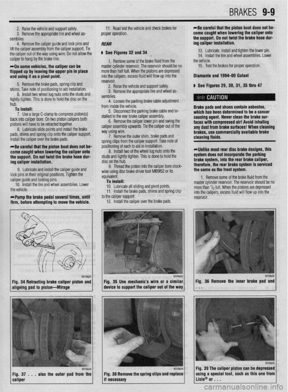
2. Raise the vehicle and support safely.
3. Remove the appropriate tire and wheel as-
semblies. 11. Road test the vehicle and check brakes for
proper operation. *Be careful that the piston boot does not be-
come caught when lowering the caliper onto
+ha n,.nnnr) lh nnt t&at thm hr&a hnra rlnr-
4. Remove the calmer auide and lock Dins and
REAR
lift the caliper assembly’from the caliper support. Tie
the caliper
out of the way using wire. 00 not allow the
caliper to hang by the brake line.
*On some vehicles, the caliper can be
flipped up by leaving the upper pin in place
and usinu it as a oivot ooint.
---- sa - . -.
5. Remove the brake pads, spring clip and
cl7knr T&n nn+n ,-A nrdtinninntn sir-4 inc+alhtinn
u See Figures 32 and 34 13. Lubricate, install and tighten the lower pin.
*
14. Install the tire and wheel assemblies. Lower
1, Remove some of the brake fluid from the the vehicle.
master cylinder reservoir. The reservoir should be no 15. Test the brakes for proper operation:
more than half full. When the p istons are depressed
into the calioers. excess fluid
3 111,113. ,(lhC ,,“LC “I p”3”‘““H’y I” a,u IIIaLcuIaLt”II. 6. Install two wheel lug nuts onto the studs and
:
lightly tighten. This is done to hold the disc on the
hub.
To install:
7. Use a large C-clamp to compress piston(s)
back into caliper bore. On two piston calipers both
pistons will have to be retracted together.
8. Lubricate slide points and install the brake
pads, shims and spring clip ont- +‘- --“n-* n**nnnA reservoir. /ill flow up into the
2. Raise the vehicle and support safely.
s tire and wheel as- 3. Remove the appropriate
semblies.
4. Loosen the parking bra
from inside the vehicle.
5. Disconnect the parking brake cable end in-
stalled to the rear brake caliper assembly.
6. Remove the caliper lower pin and swing the
caliper assembly upwards. Tie the caliper out of the
way using wire. Dlamante and 1994-00 Galant
k See Figures 29,30,31,35 thru 47
Brake pads and shoes contain asbestos,
which has been determined to be a cancer
causing agent. Never clean the brake sur-
faces with compressed air! Avoid inhaling
any dust from brake surfaces! When cleaning
brakes. use commerciallv avallable brake Ike cable adjustment
Install the caliper over the brake ,..uuG. 7. Remove the outer shim, brake pads and
.
ie caliper support. Take note of soring clips from tl
nositibning of eact
8
IndalI twn cleaning flutds. -
*Be careful that the piston boot does not be-
come caught when lowering the caliper onto
the support. Do not twist the brake hose dur-
ing caliper installation. I to aid in installation.
“. llluLull L..V of the wheel lug nuts onto the
studs and lightly tighten. This is done to hold the
disc on the hub.
Cl Thrm-l the nictnn into thP r!alinar hnre rlnrk-
*Unlike most rear disc brake designs, this
system does not incorporate the parking
brake system, into the rear brake caliper,
therefore, the rear brake system is serviced
9. Lubricate and install the caliper guide and
lock pins in their original positions. Tighten the
: caliper guide and locking pins.
10. Install the tire and wheel assemblies. Lower
the vehicle.
t *Pump the brake pedal several times, until
i
firm, before attempting to move the vehicle. V. ,,,lV”” ,,,V ~,“L”,’ III1” .IIV “..*.prv, ““I., “.“-a.
wise using disc brake driver tool MB9f52 or its
equivalent.
To install:
10. Lubricate all sliding and pivot points.
11. Install the brake pads, shims and spring clip
to the caliper support.
12. Install the caliper over ”
’ -’ ---I~ me oraxe paas. the same as the front system.
1. Remove some of the brake fluid from the
master cylinder reservoir. The reservoir should be no
more than r/a full. When the pistons are depressed
into the calipers, excess fluid will flow up into the
reservoir.
93159#2 Fig. 34 Retracting brake caliper piston and Fig. 35 Use mechanic’s wire or a similar
aligning pad to piston-hlirage device to support the caliper out of the way Fig. 36 Remove the inner brake pad and
. . .
93159p33 Fig, 37 . . . also the outer pad from the
caliper Fig. 39 The caliper piston can be depressed
Fig. 38 Remove the spring clips and replace
if necessary using a special tool, such as this one from
Lisle@ or . . .
Page 346 of 408
l
9-10 BRAKES
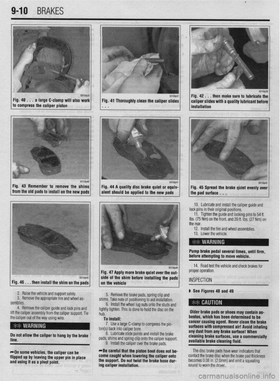
Fig. 40 . . . a large C-clamp will also work
to compress the caliper piston then make sure to lubricate the
Fig. 46
. . . then install the shim on the pads Fig. 47 Apply more brake quiet over the out-
/, the vehicle .Is/l*
wde of the sham before installing the pads
2. Raise the vehicle and support safely.
3. Remove the appropriate tire and wheel as-
semblies.
4. Remove the caliper guide and lock pins and
lift the caliper assembly from the caliper support. Tie
the caliper out of the way using wire.
( I ’ 5. Remove the brake pads, spring clip and
shims. Take note of positioning to aid installation.
6.
Do not allow the caliper to hang by the brake ’
line.
*On some vehicles, the caliper can be
flipped up by leaving the upper pin in place
and using it as a pivot point. Install the wheel lug nuts onto the studs and
lightly tighten. This is done to hold the disc on the
hub.
To install:
7. Use a large C-clamp to compress the pis-
ton(s) back into caliper bore.
_
8. Lubricate slide points and install the brake
pads, shims and spring clip onto the caliper support.
9. Install the caliper over the brake pads.
*Be careful that the piston boot
does not be- come caught when lowering the caliper onto
the support. Do not twist the brake hose dur-
ing caliper installation. Older brake pads or shoes may contain as-
bestos, which has been determined to be
cancer causing agent. Never clean the
brake
surfaces with compressed air! Avoid inhaling any dust from any brake surface! When
cleaning brake surfaces, use a commercially
available brake cleaning fluid. IO. Lubricate and install the caliper guide and
lock pins in their original positions.
11. Tighten the guide and locking pins to 54 ft.
Ibs. (75 Nm) on the front, and 20 ft. Ibs. (27 Nm) on
the rear,
12. install the tire and wheel assemblies.
13. Lower the vehicle.
Pump brake pedal several tlmes, until firm,
before attempting to move vehicle.
14. Road test the vehicle and check brakes for
proper operation.
INSPECTION
p See Figures 48 and 49
The disc brake pads have wear indicators that
contact the brake disc when the brake pad thickness
becomes 0.08 in. (2.0mm) and emit a squealing
sound to worn the driver.
Page 348 of 408
l
942 BRAKES
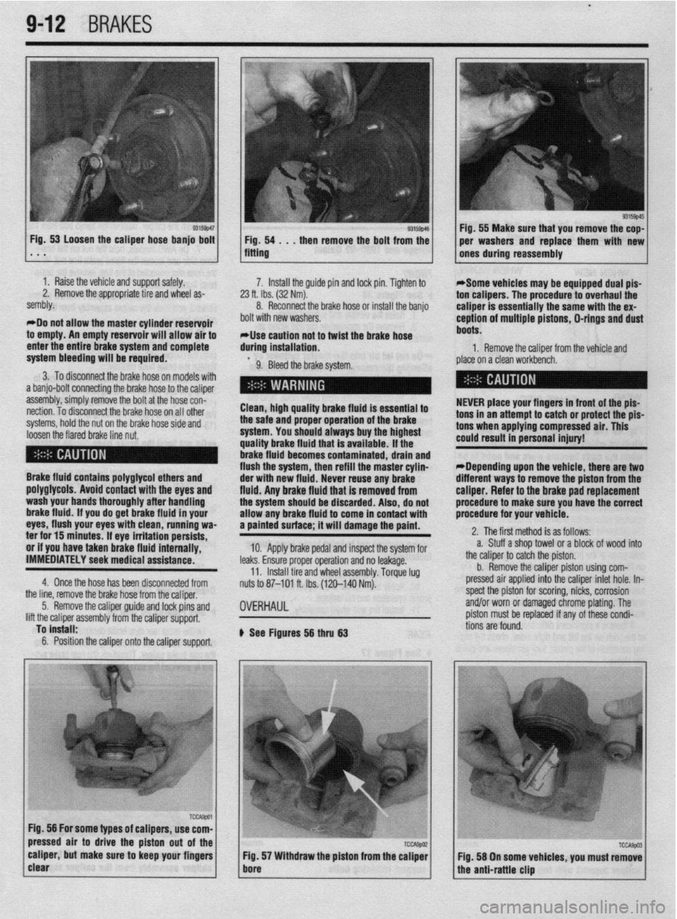
I 93155~46 Fig, 53 Loosen the caliper hose banjo bolt
1 Fig. 54 . . , then remove the bolt from the . * . fitting
1 I Raise the vehicle and support safely.
2. Remove the appropriate tire and wheel as-
sembly.
*Do not allow the master cylinder reservoir
to empty. An empty reservoir will allow air to
enter the entire brake system and complete 7. Install the guide pin and lock pin. Tighten to
23 ft. Ibs. (32 Nm).
8. Reconnect the brake hose of install the banjo
bolt with new washers.
*Use caution not to twist the brake hose
during installation.
system bleeding will be required.
9. Bleed the brake system.
3. To disconnect the brake hose on models with
a banjo-bolt connecting the brake hose to the caliper
assembly, simply remove the bolt at the hose con-
nection. To disconnect the brake hose on all other
systems, hold the nut on the brake hose side and
loosen the flared brake line nut. Clean, high quality brake fluid is essential to
the safe and proper operation of the brake
system. You should always buy the highest
quality brake fluid that is available. If the
brake fluid becomes contaminated, drain and
flush the system, then refill the master cylin-
Brake fluid contains polyglycol ethers and
poly~lycols. Avoid contact with the eves and
wash your hands thoroughly after handling
brake fluid. if you do get brake fluid In your
eyes, flush your eyes with clean, running wa-
ter for 15 minutes. If eye irritation persists,
or if you have taken brake fluid internally,
IMMEDIATELY seek medical assistance.
4. Once the hose has been disconnected from der with new fluid. Never reuse any brake
fluid. Anv brake fluid that is removed from
the systum should be discarded. Also, do not
allow any brake fluid to come in contact with
a painted surface; it will damage the paint.
10. Apply brake pedal and inspect the system for
leaks. Ensure proper operation and no leakage.
11. Install tire and wheel assembly. Torque lug
nuts to 87-101 ft. Ibs. (120-140 Nm).
the line, remove the brake hose from the caliper,
5. Remove the caliper guide and lock pins and
lift the caliper assembly from the caliper support,
To install:
6. Position the caliper onto the caliper support.
OVERHAUL
b See Figures 56 thru 63 1 Fig. 55 Make sure that you remove the cop-
per washers and replace them with new
ones during reassembly
*Some vehicles may be equipped dual pis-
ton calipers. The procedure to overhaul the
caliper is essentially the same with the ex-
ception of multiple pistons, D-rings and dust
boots.
1. Remove the caliper from the vehicle and
place on a clean workbench.
NEVER place your fingers in front of the pis-
tons in an attempt to catch or protect the pis-
tons when applying compressed air. This
could result in personal injury!
*Depending upon the vehicle, there are two
different ways to remove the piston from the
caliper. Refer to the brake pad replacement
procedure to make sure you have the correct
procedure for your vehicle.
2. The first method is as follows:
a. Stuff a shop towel or a block of wood into
the caliper to catch the piston.
b. Remove the caliper piston using com-
pressed air applied into the caliper inlet hole. In-
spect the piston for scoring, nicks, corrosion
and/or worn or damaged chrome plating. The
piston must be replaced if any of these condi-
tions are found.
Page 349 of 408
BRAKiS 9-13
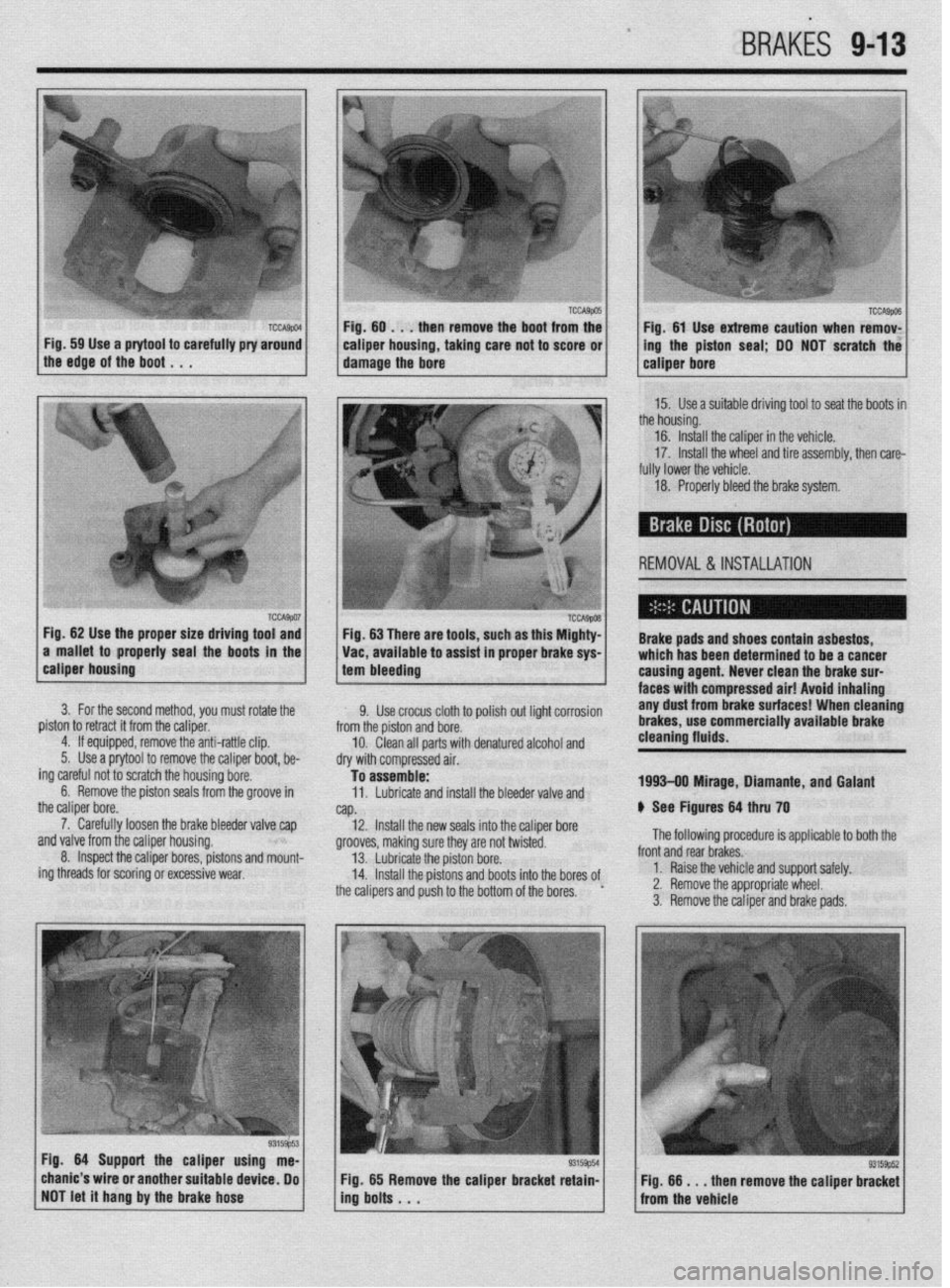
Fig. 59 Use a prytool to carefully pry around 1
the edge of the boot , , . caiper housing, taking care not to score or 1
damage the bore ing the piston seal; DO NOT scratch the
15. Use a suitable driving tool to seat the boots in
the housing.
16. Install the caliper in the vehicle.
17. Install the wheel and tire assembly, then care-
fully lower the vehicle.
18. Properly bleed the brake system.
REMOVAL &INSTALLATION
Fig. 62 Use the proper size driving tool and
a mallet to properly seal the boots in the Fig. 63 There are tools, such as this Mighty-
Vat, available to assist in proper brake sys- Brake pads and shoes contain asbestos,
which has been determined to be a cancer
calmer housino
1 tam hlasrlinn . --~-~~~v
3. For the second method, you must rotate the
piston to retract it from the caliper.
4. If equipped, remove the anti-rattle clip.
5. Use a prytool to remove the caliper boot, be-
ing careful not to scratch the housing bore.
6. Remove the piston seals from the groove in
the caliper bore.
7. Carefully loosen the brake bleeder valve cap
~nrl \I~IWJ frnm the r~linor hnlwinn
I causina aaent. LL.....” rlrr.. .I.,. l.uLr I..”
Yll” .UI”Y ll”lll LIIb rro,spl tI”“Jlly. 8. Inspect the caliper bores, pistons and mount-
ing threads for scoring or excessive wear,
--... -.---...= ’ I.twla lilci(lll Lllli uranl$ au,- faces with-compressed air! Avoid Inhaling
9. Use crocus cloth to polish out light corrosion any dust from brake surfaces! When cleaning
from the piston and bore. brakes, use commercially available brake
10. Clean all parts with denatured alcohol and cleaning fluids.
dry with compressed air.
To assemble:
11. Lubricate and install the bleeder valve and 1993-09 Mirage, Diamante, and Galant
NP. 6 See Figures 64 thru 70
12. Install the new seals into the caliper bore
nrnnlrhr m”lr;nn Clln-. M..-.., nrn n.4 h..‘“‘“~ The following procedure is applicable to both the ytvvvca, lllanllly 3”IC o,ey ale II”, IWI~LCL. 13. Lubricate the piston bore.
14. Install the pistons and boots into the bores of
the calipers and push to the bottom of the bores. ’ front and rear brakes.
1. Raise the vehicle and support safely.
2. Remove the appropriate wheel.
3. Remove the caliper and brake pads.
Fia. 64 Suoaarl the calmer usina me-
., -----= -..- chanic’s wire or another suitable device, Do
NOT let it hang by the brake hose Fig. 65 Remove the caliper bracket retain-
ing bolts . . . Fig. 66 m . . then remove the caliper bracket
from the vehicle
Page 355 of 408
BRAtiES 9-19
*Soecial flare nut wrenches shauld
REMOVAL&INSTALLATION
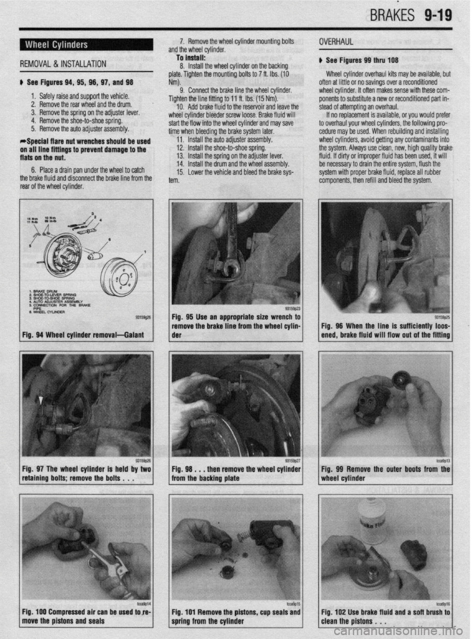
be used u See Figures 94, 95, 98, 97, and 98
1. Safely raise and support the vehicle.
2. Remove the rear wheel and the drum.
3. Remove the spring on the adjuster lever,
4. Remove the shoe-to-shoe spring.
5. Remove the auto adjuster assembly. 7. Remove the wheel cylinder mounting bolts
and the wheel cylinder.
To install:
11. Install the auto adjusterassembly. 8. Install the wheel cylinder on the backing
plate. Tighten the mounting bolts to 7 ft. Ibs. (10
Nm).
9. Connect the brake line the wheel cylinder.
Tighten the line fitting to 11 ft. Ibs. (15 Nm).
10. Add brake fluid to the reservoir and leave the
wheel cylinder bleeder screw loose. Brake fluid will
start the flow into the wheel cylinder and may save
time when bleeding the brake system later.
OVERHAUL
u See Figures 99 thru lD8
Wheel cylinder overhaul kits may be available, but
often at little or no savings over a reconditioned
wheel cvlinder. It often makes sense with these com-
ponents to substitute a new or reconditioned part in-
stead of attempting an overhaul.
If no replacement is available, or you would prefer
to overhaul your wheel cylinders, the following pro-
cedure may be used. When rebuilding and installing
wheel cylinders, avoid getting any contaminants into
the system. Always use clean, new, high quality brake
fluid. If dirty or improper fluid has been used, it will
be necessary to drain the entire system, flush the
system with proper brake fluid, replace all rubber
components, then refill and bleed the system.
Fig. 97 The wheel cylinder is held by two Fig. 98 . . . then remove the wheel cylinder
retaining bolts; remove the bolts . . . from the backing plate
/ move the pistons and seals ‘Tr 1 Fig 100 Compressed air can be used tore- Fig. 99 Remove the outer boots from the
/cleanthepistons. ‘. ‘*I6 Fig 102 Use brake fluid and a sofl brush to
Page 356 of 408
‘I
9-20 ,BRAKES
1. Remove the wheel cylinder from the vehicle
and place on a clean workbench.
2. First remove and discard the old rubber
boots, then withdraw the pistons. Piston cylinders are
equipped with seals and a spring assembly, all lo-
cated behind the pistons in the cylinder bore.
3. Remove the remaining inner components,
seals and spring assembly. Compressed air may be
useful in removing these components. If no com-
pressed air is available, be VERY careful not to score
the wheel cylinder bore when removing parts from it. Discard all components for which replacements were
supplied in the rebuild kit.
4. Wash the cylinder and metal parts in dena-
tured alcohol or clean brake fluid.
Never use a mineral-based solvent such as
gasoline, kerosene or paint thinner for clean-
ing purposes. These solvents will swell rub-
ber components and quickly deteriorate
them. 5. Allow the parts to air dry or use compressed
air. Do not use rags for cleaning, since lint will re-
main in the cylinder bore.
6. Inspect the piston and replace it if it shows
scratches.
7. Lubricate the cylinder bore and seals using
- clean brake fluid.
8. Position the spring assembly.
9. Install the inner seals, then the pistons.
IO. Insert the new boots into the counterbores bv
hand. Do not lubricate the boots,
11, Install the wheel cylinder,
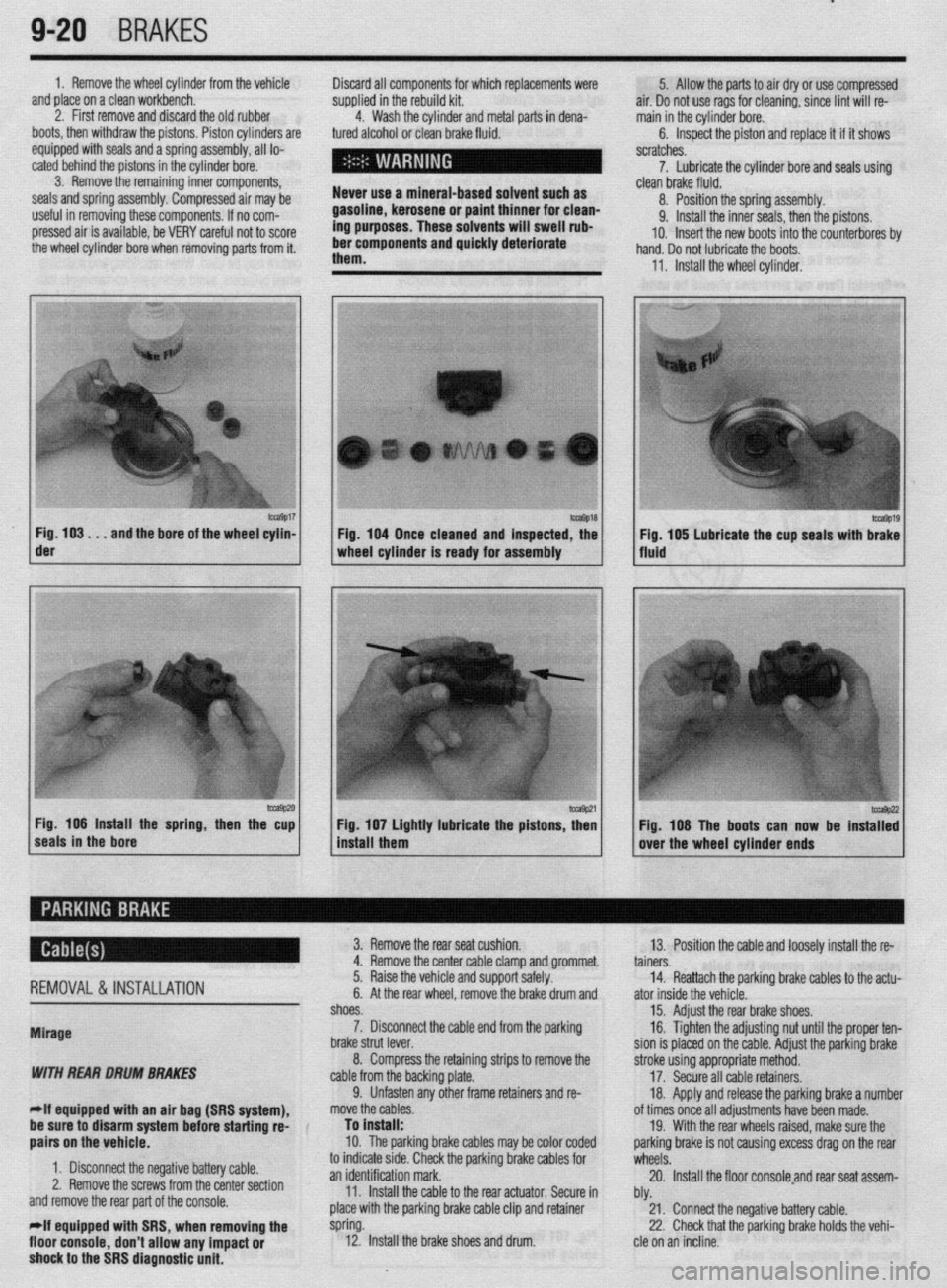
m9017 Fig. 103. . .
and the bore of the wheel cylin- der
-9P20 Fig. 106 Install the spring, then the cup
seals in the bore 1 Fig. 104 Once cleaned and inspected, the
1 wheel cylinder Is ready for assembly
1 install them Fig 107 Lightly lubricate the pistons z
’ Fig. 108 The boots can now be instaT:
over the wheel cylinder ends
REMOVAL& INSTALLATION
Mirage
WITH REAR DRUM BRAKES
-If equipped witti an air bag (SRS system), 3. Remove the rear seat cushion.
13. Position the cable and loosely install the re-
4. Remove the center cable clamp and grommet.
tainers.
5. Raise the vehicle and support safely.
14. Reattach the parking brake cables to the actu-
6. At the rear wheel, remove the brake drum and
ator inside the vehicle.
shoes.
15. Adjust the rear brake shoes.
7. Disconnect the cable end from the parking
16. Tighten the adjusting nut until the proper ten-
brake strut lever.
sion is placed on the cable. Adjust the parking brake
8. Compress the retaining strips to remove the
stroke using appropriate method.
cable from the backing plate.
17. Secure all cable retainers,
9. Unfasten any other frame retainers and re-
18. Apply and release the parking brake a number
move the cables.
of times once all adjustments have been made.
be sure to disarm system
befok starting rd-
aairs on the vehicle. To install:
10. The parkinq brake cables mav be color coded 19. With the rear wheels raised, make sure the
oarkino brake is not causina excess draa on the rear
1. Disconnect the negative battery cable.
2. Remove the screws from the center section
and remove the rear part of the console.
*If equipped with SRS, when removing the
floor console,
don’t allow any impact or
shock to the SRS diagnostic unit. to indicate stde. Check the parking brake cables for
wheels: .A
an identification mark.
20. Install the floor consoleand rear seat assem-
11. Install the cable to the rear actuator. Secure in
bly.
place with the parking brake cable clip and retainer
21. Connect the negative battery cable.
spring.
22. Check that the parking brake holds the vehi-
12. Install the brake shoes and drum.
cle on an incline.
Page 372 of 408
10-4 BODYANDTRIM
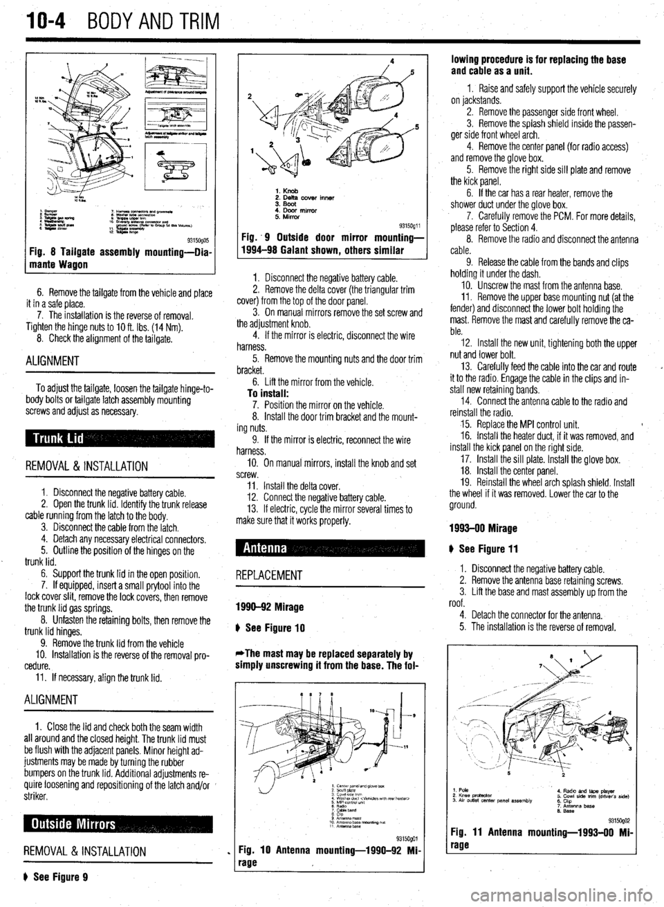
Fig. 8 Tailgate assembly mounting-Dia-
mante Wagon
6. Remove the tailgate from the vehicle and place
it in a safe place.
7. The installation is the reverse of removal.
Tighten the hinge
nuts to IO ft. Ibs. (14 Nm).
8. Check the alignment of the tailgate.
ALIGNMENT
To adjust the tailgate, loosen the tailgate hinge-to-
body bolts or tailgate latch assembly mounting
screws and adjust as necessary.
REMOVAL &INSTALLATION
1. Disconnect the negative battery cable.
2. Open the trunk lid. Identify the trunk release
cable running from the latch to the body.
3. Disconnect the cable from the latch.
4. Detach any necessary electrical connectors.
5. Outline the position of the hinges on the
trunk lid.
6. Support the trunk lid in the open position.
7. If equipped, insert a small prytool into the
lock cover slit, remove the lock covers, then remove
the trunk lid gas springs.
8. Unfasten the retaining bolts, then remove the
trunk lid hinges.
9. Remove the trunk lid from the vehicle
10. Installation is the reverse of the removal pro-
cedure.
11. If necessary, align the trunk lid.
ALIGNMENT
1. Close the lid and check both the seam width
all around and the closed height. The trunk lid must
be flush with the adjacent panels. Minor height ad-
justments may be made by turning the rubber
bumpers on the trunk lid. Additional adjustments re-
quire loosening and repositioning of the latch and/or
striker.
REMOVAL &INSTALLATION
? See Figure 9
1. Knob 2. Delta cover inner
3. Boot
4. Door mirror
5. Mirror
Fig. .9 Outside door mirror
1994-98 Galant shown
, others 9315oQ1 i mounting-
similar
1. Disconnect the negative battery cable.
2. Remove the delta cover (the triangular trim
cover) from the top of the door panel.
3. On manual mirrors remove the set screw and
the adjustment knob.
4. If the mirror is electric, disconnect the wire
harness.
5. Remove the mounting nuts and the door trim
bracket.
6. Lift the mirror from the vehicle.
To install: 7. Position the mirror on the vehicle.
8. Install the door trim bracket and the mount-
ing nuts.
9. If the mirror is electric, reconnect the wire
harness.
IO. On manual mirrors, install the knob and set
screw.
11. Install the delta cover.
12. Connect the negative battery cable.
13. If electric, cycle the mirror several times to
make sure that it works properly.
# See Figure 11
REPLACEMENT
1990-92 Mirage
b
See Figure 10
*The mast may be replaced separately by
simply unscrewing it from the base. The fol-
1. center panel and glove box
2 scuff plate
3 cowl 51ae wm
4 Washer duct
7 CaMeband
8 cap
9 Anrsnna mast
10 Antenna base “ourmng ““f
11 Antennz.base
%i%Qol
Fig. 10 Antenna mounting-1990-92 Mi-
rage lowing procedure is for replacing the base
and cable as a unit.
1 I Raise and safely support the vehicle securely
on jackstands.
2. Remove the passenger side front wheel.
3. Remove the splash shield inside the passen-
ger side front wheel arch.
4. Remove the center panel {for radio access)
and remove the glove box.
5. Remove the right side sill plate and remove
the kick panel.
6. If the car has a rear heater, remove the
shower duct under the glove box.
7. Carefully remove the PCM. For more details,
please refer to Section 4.
8. Remove the radio and disconnect the antenna
cable.
9. Release the cable from the bands and clips
holding it under the dash.
10. Unscrew the mast from the antenna base.
II. Remove the upper base mounting nut (at the
fender) and disconnect the lower bolt holding the
mast. Remove the mast and carefully remove the ca-
ble.
12. Install the new unit, tightening both the upper
nut and lower bolt.
13. Carefully feed the cable into the car and route
it to the radio. Engage the cable in the clips and in-
stall new retaining bands.
14. Connect the antenna cable to the radio and
reinstall the radio.
15. Replace the MPI control unit. t
16. Install the heater duct, if it was removed, and
install the kick panel on the right side.
17. Install the sill plate. Install the glove box.
18. Install the center panel.
19. Reinstall the wheel arch splash shield. Install
the wheel if it was removed. Lower the car to the
ground.
1993-00 Mirage
I. Disconnect the negative battery cable.
2. Remove the antenna base retaining screws.
3. Lift the base and mast assembly up from the
roof.
4. Detach the connector for the antenna.
5. The installation is the reverse of removal.
1. Pole
2. Knee protactor
3. Air outlet center panel assembly 4. Radto and laps player
5. Cowl side trim (driver’s side)
6. Chp
7. Antenna base
6. Base
931 !iogo2 Fig. 11 Antenna mounting-1993-00 Mi-
rage