1900 MITSUBISHI DIAMANTE boot
[x] Cancel search: bootPage 54 of 408
ENGINEELECTRICAL 2-7
3. Detach the electrical connectors for the COIL
4. Remove the retaining screws and coil from en-
gine.
5. Installation is the reverse of the removal proce-
dure.
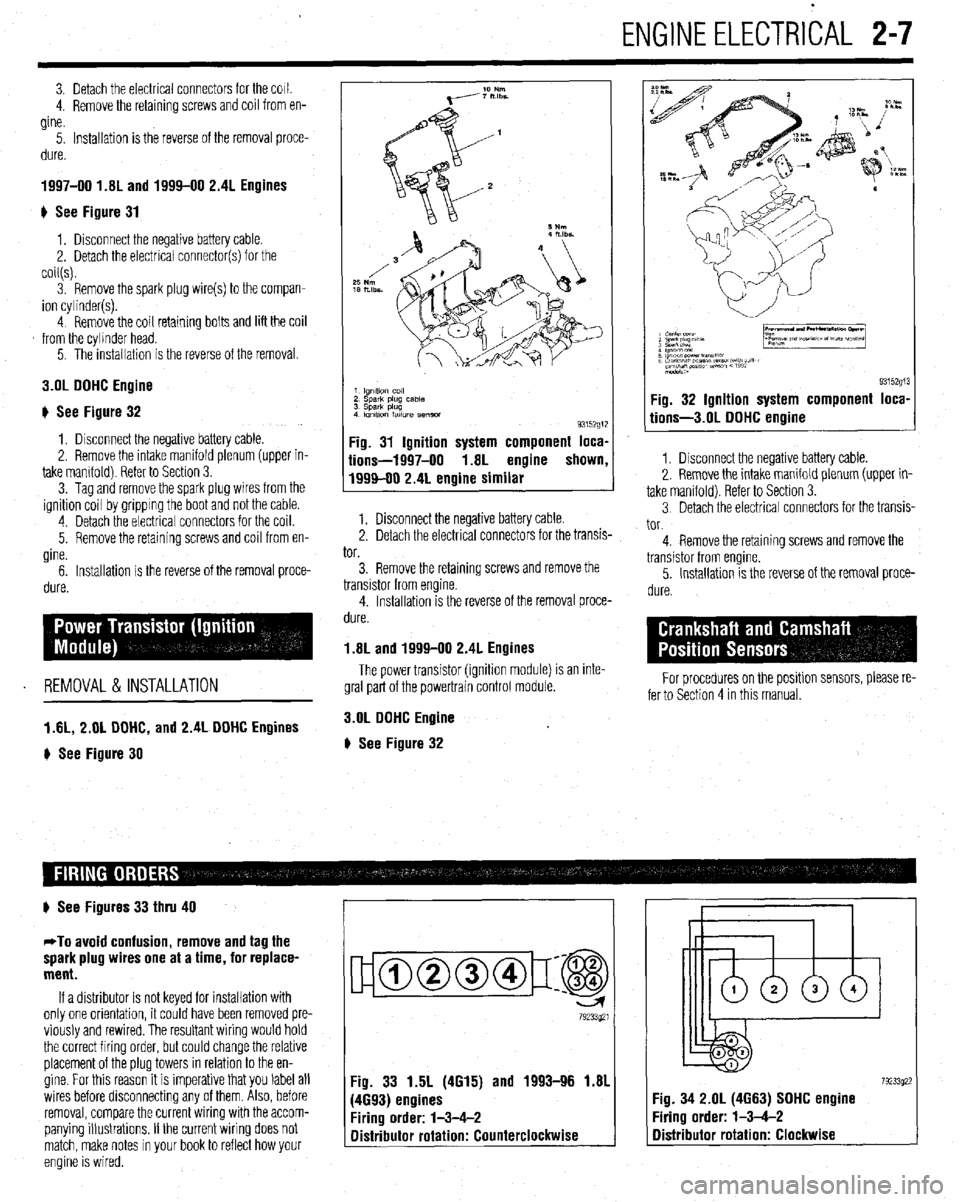
1997-00 1.81 and 1994-00 2.4L Engines
) See Figure 31
1, Disconnect the negative battery cable.
2. Detach the electrical connector(s) for the
coil(s).
3. Remove the spark plug wire(s) to the compan-
ion cylinder(s).
4 Remove the coil retaining bolts and lift the coil
from the cylinder head.
5. The installation is the reverse of the removal.
3.OL DOHC Engine
# See Figure 32
1, Disconnect the negative battery cable.
2. Remove the intake manifold plenum (upper in-
take mamfold) Refer to Section 3.
3. Tag and remove the spark plug wires from the
ignition coil by gripping the boot and not the cable.
4 Detach the electrical connectors for the coil.
5. Remove the retaining screws and coil from en-
gine.
6. Installation is the reverse of the removal proce-
dure.
REMOVAL &INSTALLATION
1 AL, 2.01 DOHC, and 2.4L DOHC Engines
) See Figure 30
1 lgnltlo” co,,
2 sparlt plug case
3 Spark plug
4 Imltlon fatlure semm
93152g1:
Fig. 31 Ignition system component loca,
iions-1997-00 1.8L engine shown
1999-00 2.4L engine similar
1. Disconnect the negative battery cable.
2. Detach the electrical connectors for the transis-
tor.
3. Remove the retaining screws and remove the
transistor from engine.
4. Installation is the reverse of the removal proce-
dure.
1.8L and 1999-00 2.4L Engines
The power transistor (ignition module) is an inte-
gral part of the powertrain control module.
3.OL DOHC Engine
# See Figure 32
9315291 Fig. 32 Ignition system component loca,
tions-3.01 DOHC engine
1. Disconnect the negative battery cable.
2. Remove the intake manifold plenum (upper in-
take manifold). Refer to Section 3.
3 Detach the electrical connectors for the transis-
tor.
4. Remove the retaining screws and remove the
transistor from engine.
5. Installation is the reverse of the removal proce-
dure.
For procedures on the positlon sensors, please re-
fer to Section 4 in this manual.
# See Figures 33 thru 40
*To avoid confusion, remove and tag the
spark plug wires one at a time, for replace-
ment.
If a distributor is not keyed for installation with
only one orientation, it could have been removed pre-
viously and rewired. The resultant wiring would hold
the correct firing order, but could change the relative
placement of the plug towers in relation to the en-
gine. For this reason it is imperative that you label all
wires before disconnecting any of them. Also, before
removal, compare the current wiring with the accom-
panying illustrations. If the current wiring does not
match, make notes in your book to reflect how your
engine is wired.
ujamm-p:@
79233921
Fig. 33 1.5L (4615) and 1993-96 1.81
(4693) engines
Firing order: l-3-4-2
Distributor rotation: Counterclockwise 7923392: :ig. 34 2.OL (4663) SOHC engine
‘iring order: l-3-4-2
Distributor rotation: Clockwise
Page 207 of 408
I
6-4 CHASSIS ELECTRICAL
I
printed circuit is sandwiched between two sheets of
plastic for more protection and flexibility. A complete l Weatherproof-these connectors are most the jumper wire is of too small a gauge, it
printed circuit, consisting of conductors, insulating commonly used where the connector is exposed to
may overheat and possibly melt. Never use
material and connectors for lamps or other compo- the elements. Terminals are protected against mois-
nents is called a printed circuit board. Printed cir- ture and dirt by sealing rings which provide a weath- jumpers to bypass high resistance loads in a
et-tight seal. All repairs require the use of a special circuit. Bypassing resistances, in effect, cre-
cuitry is used in place of individual wires or har- ates a short circuit. This may, in turn, cause
nesses in places where space is limited, such as terminal and the tool required to service it. Unlike
behind instrument panels. standard blade type terminals, these weatherproof damage and fire. Jumper wires should only
be used to bypass lengths of wire or to simu-
Since automotive electrical systems are very sen- terminals cannot be straightened once they are bent. late switches.
sitive to changes in resistance, the selection of prop- ‘Make certain that the connectors are properly seated
erly sized wires is critical when systems are repaired, and all of the sealing rings are in place when con-
netting leads. Jumper wires are simple, yet extremely valuable,
A loose or corroded connection or a replacement wire pieces of test equipment. They are basically test wires
that is too small for the circuit will add extra resis-
l Molded-these connectors require complete which are used to bypass sections of a circuit. Al-
replacement of the connector if found to be defective.
tance and an additional voltage drop to the circuit. though jumper wires can be purchased, they are usu-
The wire gauge number is an expression of the This means splicing a new connector assembly into ally fabricated from lengths of standard automotive
cross-section area of the conductor. Vehicles from the harness. All splices should be soldered to insure
proper contact. Use care when probing the connec- wire and whatever type of connector (alligator clip,
countries that use the metric system will typically de- spade connector or pin connector) that is required for
scribe the wire size as its cross-sectional area in tions or replacing terminals in them, as it is possible
square millimeters. In this method, the larger the to create a short circuit between opposite terminals. If the particular application being tested. In cramped,
hard-to-reach areas, it is advisable to have insulated
wire, the greater the number. Another common sys- this happens to the wrong terminal pair, it is possible
to damage certain components. Always use jumper boots over the jumper wire terminals in order to pre-
tern for expressing wire size is the American Wire vent accidental grounding. It is also advisable to in-
Gauge (AWG) system. As gauge number increases, wires between connectors for circuit checking and
NEVER probe through weatherproof seals. elude a standard automotive fuse in any jumper wire.
area decreases and the wire becomes smaller. An 18
gauge wire is smaller than a 4 gauge wire. A wire
l Hard Shell-unlike molded connectors, the This is commonly referred to as a “fused jumper”. By
inserting an in-line fuse holder between a set of test
terminal contacts in hard-shell connectors can be re-
with a higher gauge number will carry less current
placed. Replacement usually involves the use of a leads, a fused jumper wire can be used for bypassing :
than a wire with a lower gauge number. Gauge wire open circuits. Use a 5 amp fuse to provide protection
size refers to the size of the strands of the conductor, special terminal removal tool that depresses the lock- against voltage spikes.
not the size of the complete wire with insulator. It is ing tangs (barbs) on the connector terminal and al-
lows the connector to be removed from the rear of the Jumper wires are used primarily to locate open
possible, therefore, to have two wires of the same
shell. The connector shell should be replaced if it electrical circuits, on either the ground (-) side of the
gauge with different diameters because one may have
thicker insulation than the other. shows any evidence of burning, melting, cracks, or circuit or on the power (+) side. If an electrical corn-
breaks. Replace individual terminals that are burnt, ponent fails to operate, connect the jumper wire be-
It is essential to understand how a circuit works
corroded, distorted or loose. tween the component and a good ground. If the corn-
before trying to figure out why it doesn’t. An electrical ponent operates only with the jumper installed, the
schematic shows the electrical current paths when a ground circuit is open. If the ground circuit is good,
circuit is operating properly. Schematics break the but the component does not operate, the circuit be-
entire electrical system down into individual circuits. tween the power feed and component may be open. ’
In a schematic, usually no attempt is made to repre- Pinpointing the exact cause of trouble in an elec- By moving the jumper wire successively back from
trical circuit is most times accomplished by the use the component toward the power source, you can
; : sent wiring and components as they physically ap-
pear on the vehicle; switches and other components of special test equipment. The following describes isolate the area of the circuit where the open is lo-
are shown as simply as possible. Face views of har- different types of commonly used test equipment and cated. When the component stops functioning, or the f
j
ness connectors show the cavity or terminal locations briefly explains how to use them in diagnosis. In ad- power is cut off, the open is in the segment of wire j
in all multi-pin connectors to help locate test points. dition to the information covered below, the tool between the jumper and the point previously tested.
! manufacturer’s instructions booklet (provided with You can sometimes connect the jumper wire di-
the tester) should be read and clearly under.$ood be- rectly from the battery to the “hot” terminal of the I
CONNECTORS 1 fore attempting any test procedures. component, but first make sure the component uses 1
# See Figures 5 and 6 JUMPER WIRES 12 volts in operation. Some electrical components, i
such as fuel injectors or sensors, are designed to op-
Three types of connectors are commonly used in erate on about 4 to 5 volts, and running 12 volts di- j
)
automotive applications-weatherproof, molded and rectly to these components will cause damage.
hard shell.
Never use jumper wires made from a thinner TEST LIGHTS I
gauge wire than the circuit being tested. If
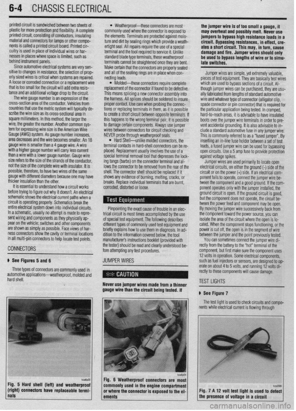
# See Figure 7
The test light is used to check circuits and compo-
I nents while electrical current is flowing through
Fig. 5 Hard shell (left) and weatherproof
(right) connectors have replaceable termi- Fig. 7 A 12 volt test light is used to di%
nals
ements 1 the presence of voltage in a circuit
Page 284 of 408
DRIVETRAIN 7-5
1, While the vehicle is still on the ground, re- IO. Insert the halfshaft into the tram&e. Be sure cle is being serviced could make a difference in joint
move the cotter pin, and loosen the axle nut. it is fully seated. type. Be sure to properly identify the joint before at-
2. Raise the vehicle and support it safely. 1 I. Pull the strut assembly out and install the tempting joint or boot replacement. Look for identifi-
3. If equipped with ABS, remove the front wheel other end to the hub. cation numbers at the large end of the boots and/or
speed sensor. 12. Install the center bearing bracket bolts and on the end of the metal retainer bands.
4. If equipped with Active Electronic Control tighten to 33 ft. Ibs. (45 Nm). The 3 types of joints used are the Birfield Joint,
Suspension (Active-ECS), perform the following: 13. Install the washer on the axle shaft so the (B.J.), the Tripod Joint (T.J.) and the Double Offset
a. Loosen the nut that secures the air line to chamfered edge faces outward. Install the axle nut, Joint (D.O.J.).
the to the top of the strut and discard the O-ring.
b. Remove the bolts that secure the actuator but do not tighten it fully at this time.
14. Connect the ball joint to the steering knuckle. *Do not disassemble a Birfield joint. Ser-
to.the top of the strut and remove the compo-
Torque the new retaining nut to 43-52 ft. Ibs. (68-72 vice with a new joint or clean and repack us-
nent. Disconnect the wiring harness.
Nm) and secure with a new cotter pin. ing a new boot kit.
5. Disconnect the lower ball joint and the tie rod
15. Connect the tie rod end to the steering
The distance between the large and small boot
end from the steering knuckle.
knuckle. Torque the retaining nut to 21 ft. Ibs. (29
bands is important and should be checked prior to
6. Remove the axle nut and the washer.
Nm) and secure with a new cotter pin.
and after boot service. This is so the boot will not be
7. If removing the left side axle with an inner 16. If equipped with ABS, install the front wheel
installed either too loose or too tight, which could
shaft, remove the center support bearing bracket speed sensor.
cause early wear and cracking, allowing the grease to
bolts and washers. Then, remove the halfshaft by set-
17. If equipped with Active-KS, perform the fol- get out and water and dirt in, leading to early joint
ting up a puller on the outside wheel hub and push-
lowing:
failure.
ing the halfshaft from the front hub. Tap the shaft a. Install the air line with a new O-ring.
union at the joint case with a plastic hammer to re- b. Install the actuator to the top of the strut. *The drfveshaft joints use special grease;
move the halfshaft and inner shaft from the transaxle. Connect the wiring harness. do not add any grease other than that sup-
8. If removing right side axle shafts without an 18. Install the wheel and lower the vehicle to the plied with the kit.
inner shaft, remove the halfshaft by setting up a floor.
puller on the outside wheel hub and pushing the half- 19. Tighten the axle nut to 145-188 ft. Ibs.
Double Offset Joint
shaft from the front hub. After pressing the outer (200-260 Nm) and secure with a new cotter pin.
shaft, insert a prybar between the transaxle case and The Double Offset Joint (D.O.J.) is bigger than
the halfshaft and pry the shaft from the transaxle.
CV-JOINTS OVERHAUL other joints and, in these applications, is normally
*Do not pull on the shaft; doing so damages used as an inboard joint.
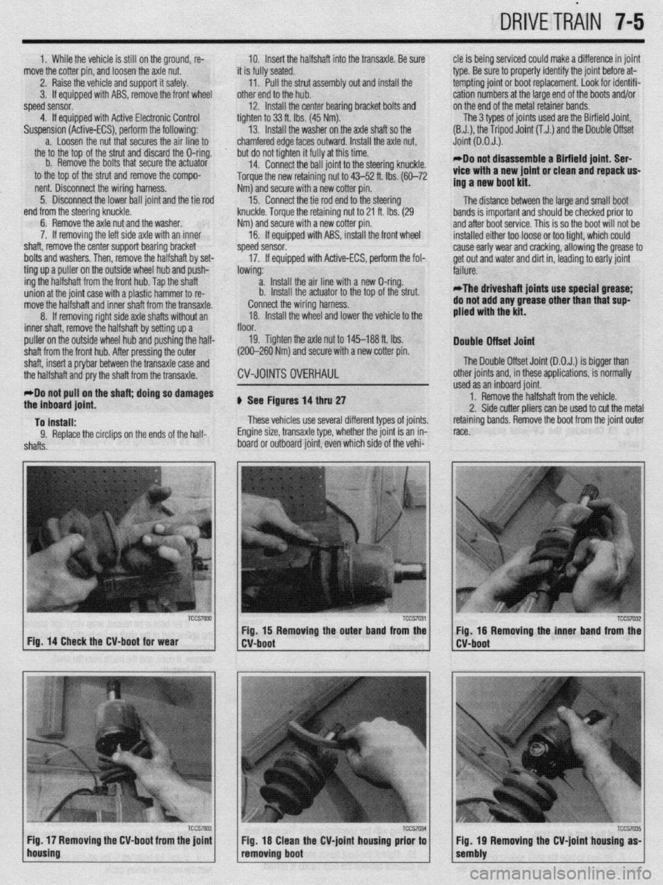
the inboard joint. b See Figures 14 thru 27 1. Remove the halfshaft from the vehicle.
2. Side cutter pliers can be used to cut the metal
To install: These vehicles use several different types of joints. retaining bands. Remove the boot from the joint outer
9. Replace the circlips on the ends of the half- Engine size, transaxle type, whether the joint is an in- race.
shafts. board or outboard joint, even which side of the vehi-
TCCS7030 TCCS7031
I I TCCS7032 Fig. 15 Removing the outer band from the
Fig. 16 Removing the inner band from the
Fig. 14 Check the CV-boot for wear
W-boot
lho~sing IFi7~ / Fig 17 Removing the CV-boot from the joint 1 1 CV-boot
TCCS7035 Fig 18 Clean the CV-joint housing prior to
removing boot Tccs7W 1 1 sembiy Fig 19 Removing the CV-joint housing as-
Page 285 of 408
-
7-6 DRIVETRAIN
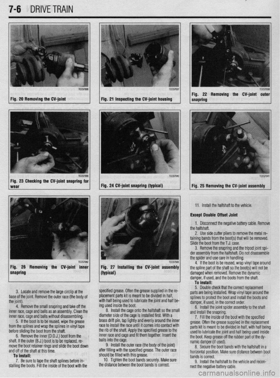
fig. 20 Removing the CV-joint Fig. 21 inspecting the M-joint housing
TCCS7042 1 Fig. 26 Removing the CV-joint inner
snapring Fig, 27 installing the CV-joint assembly Removing the CV-joint outer
Fig. 25 Removing the CV-joint assembly
11. Install the halfshaft to the vehicle.
Except Double Otfset Joint
1. Disconnect the neaative batterv cable. Remove
the halfshaft. - ’
2. Use side cutter oliers to remove the metal re-
taining bands from the boot(s) that will be removed.
Slide the boot from the T.J. case.
3. Remove the snapring and the tripod joint spi-
der assembly from the halfshaft. Do not disassemble
the spider and use care in handling.
4. If the boot is be reused, wrap vinyl tape around
the spline part of the shaft so the boot(s) will not be
I
3. Locate and remove the large circlip at the ’
base of the joint. Remove the outer race (the body of
the joint).
4. Remove the small snapring and take off the
inner race, cage and balls as an assembly. Clean the
inner race, cage and balls without disassembling.
5. If the boot is to be reused. wioe the arease
from the splines and wrap the splfnes in vin$ tape
before sliding the boot from the shaft.
6. Remove the inner (D.O.J.) boot from the
shaft. If the outer (B.J.) boot is to be replaced, re-
move the boot retainer rings and slide the boot down
and off of the shaft at this time.
To install:
7. Be sure to tape the shaft splines before in-
stalling the boots. Fill the inside of the boot with the (typiW
1
specified grease. Often the grease supplied in the re-
placement parts kit is meant to be divided in half,
with half being used to lubricate the joint and half be-
ing used inside the boot.
Install the cage onto the halfshaft so the small 8.
diameter side of the cage is installed first. With a
brass drift pin, tap lightly and e ’ ’ ‘* ’
nemy arouna me Inner
race to install the race until it comes into contact with
the rib of the shaft. Apply the specified grease to the
inner race and cage and fit them together. Insert the
balls into the cage.
9. Install the outer race (the body of the joint)
after filling with the specified grease. The outer race
should be filled with this greas e.
10. Tighten the boot bands
securely. Make sure
the distance between the boot t,, IuJ IJ ,,“I lGbl. \onrlo i.i *nrro”+ damaged when removed. Remove the dynamic
To install: damper, if used, and the boots from the shaft.
5. -
Double check that the correct replacement
parts are being installed. Wrap vinyl tape around the
splines to protect the boot and install the boots and
damper, if used, in the correct order,
6. Install the joint spider assembly to the shaft
and ipctdl the cnmrinn 7. Fill the inside ofthe boot with the specified
grease. Often the grease supplied in the replacement
parts kit is meant to be divided in half, with half being
used to lubricate the joint and half being used inside
the boot. Keep grease off the rubber part of the dy-
namic damper (if used).
8. Secure the boot bands with the halfshaft in a
horizontal position. Make sure distance between boot
bands is correct.
9. Install the halfshaft to the vehicle and recon-
nect
the negative battery cable.
Page 293 of 408
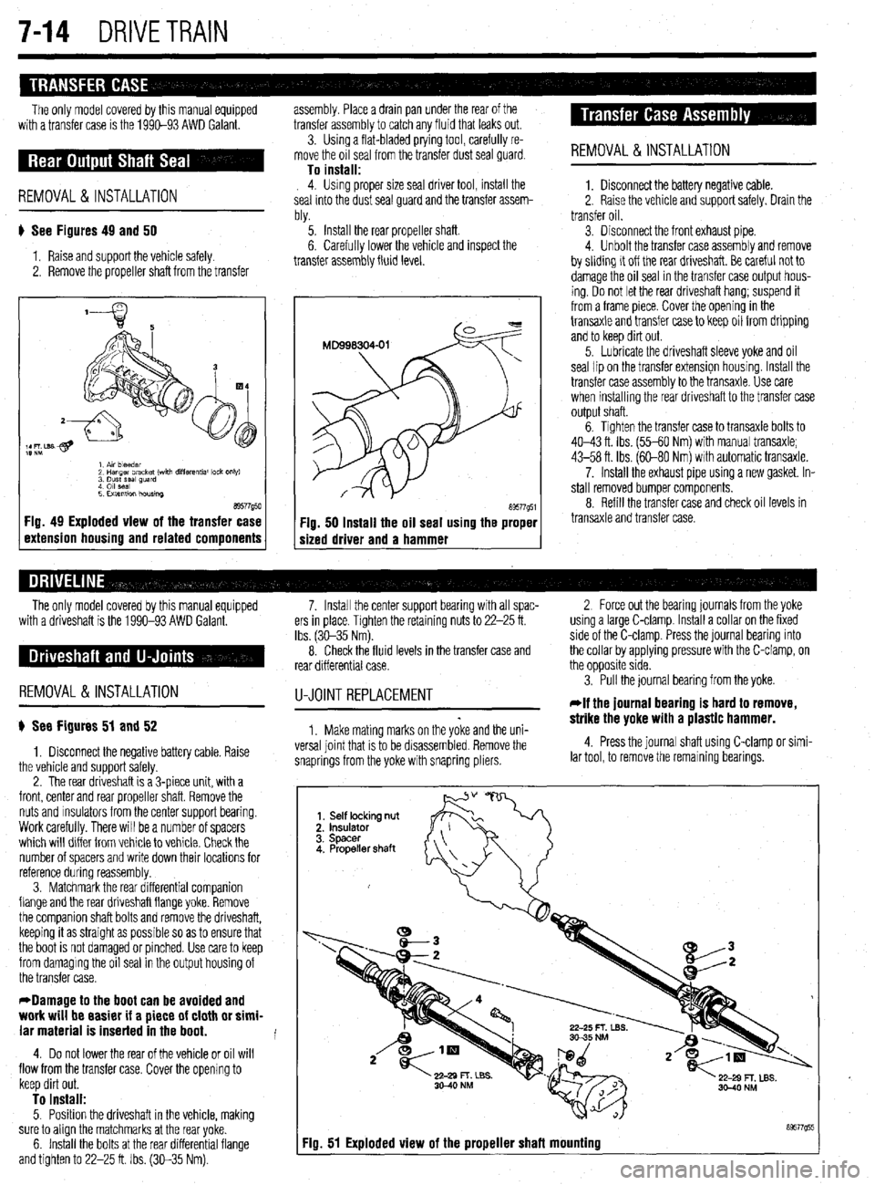
7-14 DRIVETRAIN
The only model covered by this manual equipped
with a transfer case is the 1990-93 AWD Galant. assembly. Place a drain pan under the rear of the
transfer assembly to catch any fluid that leaks out.
3. Usinq a flat-bladed prying tool, carefully re-
REMOVAL &INSTALLATION
move the ofi seal from the transfer dust seal guard
To install: 4. Using proper size seal driver tool, install the
seal into the dust seal quard and the transfer assem-
blv.
# See Figures 49 and 50
1. Raise and support the vehicle safely.
2. Remove the propeller shaft from the transfer ‘5. Install the rear propeller shaft.
6. Carefully lower the vehicle and inspect the
transfer assembly fluid level.
a9577g50 1 Fig. 49 Exploded view of the transfer case
1 extension housing and related components a9577g51 Fig. 50 Install the oil seal using the proper
sized driver and a hammer REMOVAL &INSTALLATION
1. Disconnect the battery negative cable.
2. Raise the vehicle and support safely. Drain the
transfer oil.
3. Disconnect the front exhaust pipe.
4. Unbolt the transfer case assembly and remove
by sliding it off the rear driveshaft. Be careful not to
damage the oil seal in the transfer case output hous-
ing. Do not let the rear driveshaft hang; suspend it
from a frame piece. Cover the opening in the
transaxle and transfer case to keep oil from dripping
and to keep dirt out.
5. Lubricate the driveshaft sleeve yoke and oil
seal lipan the transfer extension housing. Install the
transfer case assembly to the transaxle. Use care
when installing the rear driveshaft to the transfer case
output shaft.
6. Tighten the transfer case to transaxle bolts to
40-43 ft. Ibs. (55-60 Nm) with manual transaxle;
43-58 ft. Ibs. (60-80 Nm) with automatic transaxle.
7. Install the exhaust pipe using a new gasket. In-
stall removed bumper components.
8. Refill the transfer case and check oil levels in
transaxle and transfer case.
The only model covered by this manual equipped
with a driveshaft is the 1990-93 AWD Galant.
REMOVAL &INSTALLATION
) See Figures 51 and 52
1. Disconnect the negative battery cable. Raise
the vehicle and support safely.
2. The rear driveshaft is a 3-piece unit, with a
front, center and rear propeller shaft. Remove the
nuts and msulators from the center support bearing.
Work carefully. There will be a number of spacers
which will differ from vehicle to vehicle. Check the
number of spacers and write down their locations for
reference during reassembly.
3. Matchmark the rear differential companion
flange and the rear driveshaft flange yoke. Remove
the companion shaft bolts and remove the driveshaft,
keeping it as straight as possible so as to ensure that
the boot is not damaged or pinched. Use care to keep
from damaging the oil seal in the output housing of
the transfer case.
*Damage to the boot can be avoided and
work will be easier if a piece of cloth or simi-
lar material is inserted in the boot.
4. Do not lower the rear of the vehicle or oil will
flow from the transfer case. Cover the opening to
keep dirt out.
To install: 5. Position the driveshaft in the vehicle, making
sure to align the matchmarks at the rear yoke.
6. Install the bolts at the rear differential flange
and tighten to 22-25 ft. Ibs. (30-35 Nm). 7. Install the center support bearing with all spac- 2 Force out the bearing journals from the yoke
ers in place. Tighten the retaining nuts to 22-25 ft. using a large C-clamp. Install a collar on the fixed
Ibs. (3C-35 Nm). side of the C-clamp. Press the journal bearing into
8. Check the fluid levels in the transfer case and the collar by applying pressure with the C-clamp, on
rear differential case. the opposite side.
U-JOINTREPLACEMENT
1. Make mating marks on the yoke and the uni-
versa1 joint that is to be disassembled. Remove the
snaprings from the yoke with snapring pliers. 3. Pull the journal bearing from the yoke.
rlf the journal bearing is hard to remove,
strike the yoke with a plastic hammer.
4. Press the journal shaft using C-clamp or simi-
lar tool, to remove the remaining bearings.
Fiu. 51 Exploded view of the proueller shafl mounting
Page 294 of 408
DRIVETRAiN 7-15
MATING MARKS
/
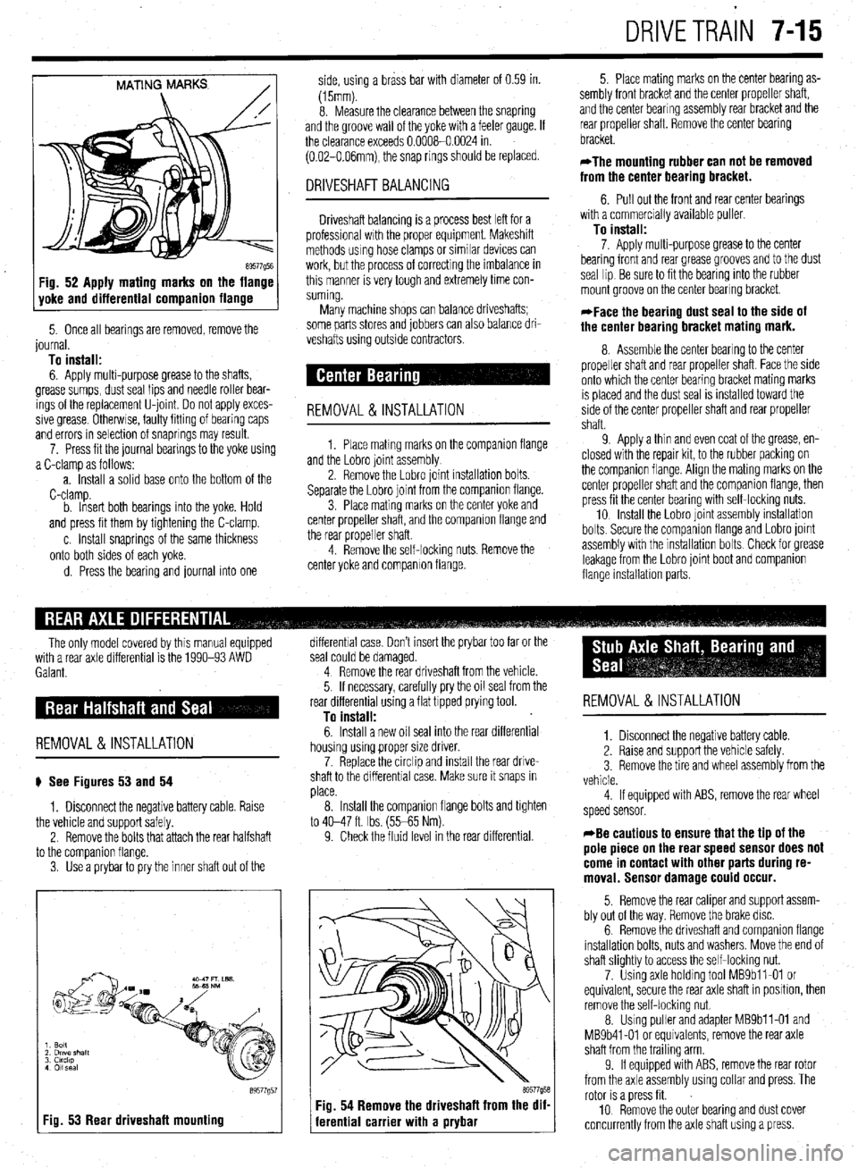
89577Q5E Fig. 52 Apply mating marks on the flange
yoke and differential companion flange
5. Once all bearings are removed, remove the
journal.
To install:
6. Apply multi-purpose grease to the shafts,
grease sumps, dust seal lips and needle roller bear-
ings of the replacement U-joint Do not apply exces-
sive grease Otherwse, faulty fitting of bearing caps
and errors in selection of snaprings may result.
7. Press fit the journal bearings to the yoke using
a C-clamp as follows:
a. Install a solid base onto the bottom of the
C-clamp.
b. Insert both bearings into the yoke. Hold
and press fit them by tightening the C-clamp.
c. Install snaprings of the same thickness
onto both sides of each yoke.
d. Press the bearing and journal into one side, using a brass bar with diameter of 0.59 in.
(15mm).
8. Measure the clearance between the snapring
and the groove wall of the yoke with a feeler gauge. If
the clearance exceeds 0.0008-0.0024 in.
(0.02-O.O6mm), the snap rings should be replaced.
DRIVESHAFT BALANCING
Driveshaft balancing is a process best left for a
professional wrth the proper equipment. Makeshift
methods using hose clamps or similar devices can
work, but the process of correcting the imbalance in
this manner is very tough and extremely time con-
suming.
Many machine shops can balance driveshafts;
some parts stores and jobbers can also balance dri-
veshafts using outside contractors.
REMOVAL&INSTALLATION
1. Place matmg marks on the companron flange
and the Lobro joint assembly
2. Remove the Lobro joint installation bolts.
Separate the Lobro joint from the companion flange.
3. Place mating marks on the center yoke and
center propeller shaft, and the companion flange and
the rear propeller shaft.
4. Remove the self-locking nuts. Remove the
center yoke and companion flange. 5. Place mating marks on the center bearing as-
sembly front bracket and the center propeller shaft,
and the center bearing assembly rear bracket and the
rear propeller shaft. Remove the center bearing
bracket.
*The mounting rubber can not be removed
from the center bearing bracket.
6. Pull out the front and rear center bearings
with a commercially available puller
To install:
7. Apply multi-purpose grease to the center
bearing front and rear grease grooves and to the dust
seal lip Be sure to fit the bearing into the rubber
mount groove on the center bearing bracket.
*Face the bearing dust seal to the side of
the center bearing bracket mating mark.
8. Assemble the center bearing to the center
propeller shaft and rear propeller shaft. Face the side
onto which the center bearing bracket mating marks
IS placed and the dust seal is installed toward the
side of the center propeller shaft and rear propeller
shaft.
9 Apply a thin and even coat of the grease, en-
closed with the repair kit, to the rubber packing on
the companion flange. Align the mating marks on the
center propeller shaft and the companion flange, then
press fit the center bearing with self-locking nuts.
10 Install the Lobro joint assembly installation
bolts. Secure the companron flange and Lobro joint
assembly with the installation bolts Check for grease
leakage from the Lobro joint boot and companion
flange installabon parts.
The only model covered by this manual equipped
with a rear axle differential is the 1990-93 AWD
Galant.
REMOVAL &INSTALLATION
# See Figures 53 and 54
1. Disconnect the negative battery cable. Raise
the vehicle and support safely.
2. Remove the bolts that attach the rear halfshaft
to the comoanion flanae.
3. Use’a prybar topry the inner shaft out of the
I Fig. 53 Rear driveshaft mounting
89577g5
differential case. Don’t insert the prybar too far or the
seal could be damaged.
4 Remove the rear driveshaft from the vehicle.
5. If necessary, carefully pry the oil seal from the
rear differential using a flat tipped prying tool.
To install:
6. Install a new oil seal into the rear differential
housing using proper size driver.
7. Replace the circlip and install the rear drive-
shaft to the differential case. Make sure it snaps in
place.
8. Install the companion flange bolts and tighten
to 40-47 ft. Ibs. (55-65 Nm).
9. Check the fluid level in the rear differential.
69577958 Fig. 54 Remove the driveshaft from the dif-
ferential carrier with a prybar
REMOVAL &INSTALLATION
1. Disconnect the negative battery cable.
2. Raise and support the vehicle safely.
3 Remove the tire and wheel assembly from the
vehicle.
4 If equipped with ABS, remove the rear wheel
speed sensor.
*Be cautious to ensure that the tip of the
pole piece on the rear speed sensor does not
come in contact with other parts during re-
moval. Sensor damage could occur.
5. Remove the rear caliper and support assem-
bly out of the way. Remove the brake disc.
6. Remove the driveshaft and companion flange
installation bolts, nuts and washers. Move the end of
shaft slightly to access the self-locking nut.
7. Using axle holding tool MBSbll-01 or
equivalent, secure the rear axle shaft in position, then
remove the self-locking nut.
8. Using puller and adapter MBSbll-01 and
MB9b41-01 or equivalents, remove the rear axle
shaft from the trailing arm
9. If equipped with ABS, remove the rear rotor
from the axle assembly using collar and press. The
rotor is a press fit.
10 Remove the outer bearing and dust cover
concurrently from the axle shaft using a press.
Page 328 of 408
.
8132 SUSPENSION AND STEERING
(42 Nm) on Mirage and 36-39 ft. tbs. (49-53 Nm)
on Galant and Diamante models.
19. Have the front end alignment checked, and
adjusted if necessary.
Inner Tie Rods
11. Loosen the inner tie rod end nut from the
steering gear and remove the inner tie rod end.
To install: 12. Using a new lock plate, install the tie rod end
and tighten the tie rod to 65 ft. Ibs. (90 Nm). REMOVAL &INSTALLATION 13. Bend the tabs of the new lock plate to secure
1. Raise the front of the vehicle and support it
on jackstands.
2. Remove the wheel.
3. Remove the cotter pin and the outer tie rod
ball joint stud nut. Note the position of the steering
linkage.
4. Wire brush the threads on the tie rod shaft
and lubricate with penetrating oil.
5. Using a suitable ball joint separator tool, re-
move the tie rod ball joint from the steering knuckle.
6. Loosen the locknut and remove the tie rod
end from the tie rod. Count the number of complete
turns it takes to completely remove it.
7. Remove the tie rod-to-steering gear locknut.
8. Remove the clamps that secure the flexible
boot to the steering gear.
9. Slide the boot from the inner tie rod and re-
move the boot.
IO. Bend the lock plate tabs from the inner tie rod
end nut. the inner tie rod end.
14. Slide the boot onto the steering gear and se-
cure it with new clamps.
15. Install the outer tie rod end to the steering
gear locknut.
16. Install the outer tie rod end, turning it in ex-
actly as many turns as it was to remove the old one.
Make sure it is correctly positioned in relationship to
the steering linkage.
22. Have a front end alignment performed. 17. Connect the outer tie rod end to the steering
knuckle and install the castle nut. Tighten the nut to
25 ft. Ibs. (34 Nm,) on the Mirage and 21 ft. Ibs. (29
Nm) on the Galant and Diamante models.
18. Install a new cotter pin to the castle nut.
19. Tighten the tie rod end locking nut to 30 ft.
Ibs. (42 Nm) on the Mirage and 36-39 ft. Ibs. (49-53
Nm) on the Galant and Diamante models.
20. Install the wheel and tire assembly.
21. Lower the vehicle.
Mirage
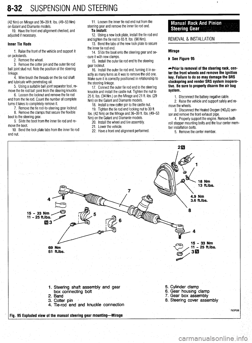
) See Figure 95
*Prior to removal of the steering rack, cen-
ter the front wheels and remove the ignition
key. Failure to do so may damage the SRS
clockspring and render SRS system inopera-
tive. Be sure to properly disarm the air bag
system.
1. Disconnect the battery negative cable.
2. Raise the vehicle and support safely and re-
move the wheels.
5. Remove the center member. 3. Disconnect the Heated Oxygen (HOzS) sen-
sor and remove the front exhaust pipe.
4. Properly support the engine. Remove both
roll stopper mounting bolts and the four center mem-
ber installation bolts.
18
Nm 13 ft.lbs.
15 - 33 Nm /
11 - 25 ft.lbs. 7
03
L
69 Nm
51 ftlbs.
4.9 Nm 3.6 ft.lbs.
11 - 25 ft.lbs.
1. Steering shaft assembly and
gear box connecting bolt
2. Band
3. Cotter pin I
4. Tie-rod end and knuckle connection 5. Cylinder clamp
6. Gear housing clamp
7. Gear box assembly
8. Steering cover assembly
Fig. 95 Exploded view of the manual steering gear mounting-Mlrage
Page 329 of 408
SUSPENSION AND STEERING 8-33
*Matchmark the pinion input shaft of the
rack to the lower steering column joint for in-
stallation purposes.
6. Remove the pinch bolt holding the lower
steering column joint to the rack and pinion input
shaft.
7. Remove the cotter pins and disconnect the tie
rod ends from the steering knuckle.
8. Remove the rack and pinion steering assem-
bly and its rubber mounts from the right side of the
vehicle.
To install: 9. Align the matchmarks of the input shaft and
install the rack to the vehicle.
10. Secure the rack using the retainer clamps and
bolts. Tighten the bolts to 51 ft. Ibs. (70 Nm).
11. Tighten the steering column pinch bolt to 13
ft. Ibs. (18 Nm).
12. Install the center member.
13. Install the front exhaust pipe.
14. Connect the HO$ sensor.
15. Connect the tie rod ends to the steering
knuckles and tighten the castle nuts to 25 ft. Ibs. (34
Nm). Install new cotter pins.
16. Install the wheels and connect the negative
battery cable.
17. Have a front end alignment performed.
REMOVAL &INSTALLATION
Diamante
FRONT
*Prior to removal of the steering gear box,
center the front wheels and remove the igni-
tion key. Failure to do so may damage the
SRS clock spring and render SRS system in-
operative.
1. Disconnect the negative battery cable.
2. Disconnect the front exhaust pipe.
3. If equipped with AWD, remove the transfer
case assembly.
4. Remove the bolt holding the lower steering
column joint to the rack and pinion input shaft.
5. Remove the cotter pins and disconnect the tie
rod ends.
6. Remove the left and right frame members.
7. Remove the stabilizer bar bracket.
8. If equipped with four-wheel steering, discon-
nect the lines going to the rear pump.
9. Remove the rack and pinion steering assem-
bly and its rubber mounts. Move the rack to the right
to remove it from the crossmember.
To install: IO. Install the rack and mounting bolts. Tighten
the bolts to 51 ft. Ibs. (70 Nm). When installing the
rubber rack mounts, align the projection of the
mounting rubber with the indentation in the cross:
member. Install the pinch bolt.
11. Connect the pressure and return lines to the
rack and to the rear pump, if equipped.
12. Install the frame members and tighten the
bolts to 43-51 ft. Ibs. (60-70 Nm).
13. Connect the tie rods and install new cotter
pins. 14. Install the transfer case and front exhaust
pipe.
15. Refill the reservoir and bleed the system.
16. Have a front end alignment performed.
REAR
1. Disconnect the negative battery cable.
2. Raise the vehicle and support safely.
3. Drain the power steering fluid.
4. Remove the main muffler assembly.
5. Remove the rear shock absorber lower
mounting bolts.
6. Using the proper equipment, support the
weight of the rear differential. Remove the 2 small
crossmember brackets.
7. Remove the large self-locking crossmember
mounting nuts on the differential side.
8. Remove the oil line clamp bolts.
9. Remove the pressure tubes.
IO. Hold the tie rod ends stationary and remove
the tie rod end nuts. Remove the tie rod ends from
the trailing arms.
11. Remove the mounting bolts and remove the
rear steering gear.
To install: 12. Secure the unit to the crossmember. Move
the power cylinder piston rod over its full stroke to
determine its neutral position.
13. Align the tie rod ends with the holes in the
trailing arms and install the nuts. Adjust the length of
the tie rods with the nuts if necessary. The difference
in length between the 2 tie rod ends should not ex-
ceed 0.04 in. (1 mm). The nuts’ torque specification is
42 ft. Ibs. (58 Nm).
14. Replace the O-rings and install the pressure
tubes. Clamp in place.
15. Install the large self-locking crossmember
mounting nuts on the differential side. Tighten to
80-94 ft. Ibs. (110-130 Nm).
16. Remove the support equipment.
17. Install the 2 small crossmember brackets.
18. Install the shock mounting bolts.
19. Install the muffler assembly.
20. Refill the reservoir and bleed the system.
21. Have a front end alignment performed. _
Galant
1990-93 MODELS
1. Disconnect the negative battery cable.
2. Drain the power steering fluid.
3. Raise the vehicle and support safely.
4. Remove the bolt holding lower steering col-
umn joint to the rack and pinion input shaft.
5. Remove the transfer case, if equipped.
6. Remove the cotter pins and using the proper
tools, separate the tie rod ends from the steering
knuckle.
7. Locate the triangular brace near the stabilizer
bar brackets on the crossmember and remove both
the brace and the stabilizer bar bracket.
8. Support the center crossmember.
9. Remove the through-bolt from the round roll
stopper and remove the rear bolts from the center
crossmember.
10. Disconnect the front exhaust pipe, if
equipped with FWD.
11. Disconnect the power steering fluid pressure
pipe and return hose from the rack fittings. Plug the
fittings to prevent excess fluid leakage. 12. Lower the crossmember slightly.
13. Remove the rack and pinion steering assem-
bly and its rubber mounts. Move the rack to the right
to remove from the crossmember. Tilt the assembly
downward and remove from the left side of the vehi-
cle. Use caution to avoid damaging the boots.
To install: 14. Install the rack and install the mounting bolts. Tighten the mounting bolts to 43-58 ft. Ibs. (60-80
Nm). When installing the rubber rack mounts, align
the projection of the mounting rubber with the inden-
tation in the crossmember.
15. Connect the power steering fluid lines to the
rack.
16. Connect the exhaust pipe, if removed.
17. Raise the crossmember into position. Install
the center member mounting bolts and tighten to 72
ft. Ibs. (100 Nm). Install the roll stopper bolt and new
nut. Tighten nut to 47 ft. Ibs. (65 Nm).
18. Install the stabilizer bar brackets and brace.
19. Connect the tie rod ends and tighten nuts to
25 ft. Ibs. (34 Nm).
20. Install the transfer case, if removed. Check
and fill fluid.
21. Refill the reservoir with power steering fluid
and bleed the system.
22. Have a front end alignment performed.
1994-M MODELS
+ See Figure 96
Prior to removal of the steering gear box,
center the front wheels and remove the igni-
tion key. Failure to do so may damage the
SRS clock spring and render SRS system in-
operative.
1. Disconnect the negative battery cable.
2. Raise and properly support the vehicle.
3. Remove both front wheel assemblies.
4. Remove the bolt holding lower steering col-
umn joint to the rack and pinion input shaft.
5. Remove the stabilizer bar.
6. Remove the cotter pins, and using joint sepa-
rator MB991 113 or equivalent, disconnect the tie rod
ends from the steering knuckle.
7. On vehicles equipped with Electronic Control
Power steering (EPS), detach the wiring harness from
the solenoid connector.
8. Locate the two triangular braces near the
crossmember and remove both.
9. Support the center crossmember. Remove the
through-bolt from the front round roll stopper and re-
move the bolts securing the center crossmember.
10. Remove the center crossmember. ,
Il. Properly support the engine and remove the
rear roll stopper through-bolt.
12. Disconnect the power steering fluid pressure
pipe and return hose from the rack fittings. Plug the
fittings to prevent excessive fluid leakage.
13. Remove the clamp bolts and the two bolts se-
curing the rack assembly to the chassis.
14. Remove the rack and pinion steering assem-
bly and its rubber mounts.
*When removing the rack and pinion as-
sembly, tilt the assembly to the vehicle side
of the compression lower arm and remove
from the left side of the vehicle.