1900 MITSUBISHI DIAMANTE boot
[x] Cancel search: bootPage 1 of 408
HOW TO USE THIS BOOK 1-2
WHERE TOBEGIN l-2
AVOIDINGTROUBLE 1-2
MAINTENANCEORREPAIR? 1-2
AVOIDINGTHEMOSTCOMMONMISTAKES l-2
TOOLS AND EQUIPMENT 1-2
SPECIALTOOLS l-4
YOUR VEHICLE SAFELY 1-4
DON'TS l-6
FASTENERS, MEASUREMENTS AND
CONVERSIONS l-6
BOLTS,NUTSANDOTHERTHREADED
RETAINERS 1-6
TORQUE l-7
TORQUEWRENCHES l-7
TORQUEANGLEMETERS 1-9
STANDARDANDMETRIC MEASUREMENTS l-9
SERIAL NUMBER IDENTIFICATION l-10
VEHICLE IDENTIFICATION NUMBER l-10
ENGINE IDENTIFICATION NUMBER I-10
TRANSAXLEIDENTIFICATION I-10
DRlVEAXLE(AWDGALANTONLY) l-10
TRANSFERCASE(AWDGALANTONLY) l-10
ROUTINE MAINTENANCE AND TUNE-UP l-14
AIRCLEANER(ELEMENT) 1-14
REMOVAL&INSTALLATION 1-14
FUELFILTER 1-15
REMOVAL &INSTALLATION l-15
PCVVALVE l-15
REMOVAL&INSTALLATION l-15
EVAPORATIVECANISTER l-16
SERVICING 1-16
BATTERY 1-16
PRECAUTIONS I-16
GENERALMAINTENANCE 1-16
BEL BATTERYFLUID 1-16
CABLES I-17
CHARGING I-18
REPLACEMENT 1-18
TS 1-18
INSPECTiON l-18
ADJUSTMENT 1-18
REMOVAL&INSTALLATION 1-18
TIMINGBELTS l-20
INSPECTION l-20
HOSES I-20
INSPECTION l-20
REMOVAL&INSTALLATION
CV-BOOTS 1-21
INSPECTION l-21
SPARKPLUGS l-22
SPARKPLUGHEATRANGE
REMOVAL&INSTALLATION
INSPECTION &GAPPING 1.
SPARKPLUG WIRES 1-24
TESTING 1-24
REMOVAL&INSTALLATION
DISTRIBUTORCAPANDROTOR
REMOVAL&INSTALLATION
INSPECTION 1-25
IGNITIONTIMING 1-25
. GENERALINFORAMTION l-
lNSPECTlON&ADJUSTMENl
VALVE LASH l-27
ADJUSTMENT l-27
IDLESPEED 1-28 1-21
l-22
l-22
-23
1-24
l-25
l-25
.25
1-26
AIR CONDITIONING SYSTEM 1-28
SYSTEMSERVlCEiiREPAlR l-28
PREVENTIVEMAINTENANCE 1-28
SYSTEM INSPECTION l-29
WINDSHIELD WIPERS l-29
ELEMENT(REFILL)CARE&
REPLACEMENT l-29
TIRESANDWHEELS l-30
TIRE ROTATION I-30
TIRE DESIGN 1-31
TIRESTORAGE l-31
INFLATION &INSPECTION l-31
CARE OFSPECIALWHEELS l-32 OPERATION INFOREIGNCOUNTRIES l-33
ENGINE l-33
OILLEVELCHECK 1-33
OIL& FILTER CHANGE l-34
MANUALTRANSAXLE l-35
FLUIDRECOMMENDATIONS l-35
LEVELCHECK l-35
DRAIN&REFILL l-36
AUTOMATICTRANSAXLE l-36
FLUIDRECOMMENDATIONS l-36
LEVELCHECK 1-36
DRAIN&REFILL l-36
PAN & FILTERSERVICE 1-36
TRANSFERCASE(AWDGAlANT ONLY) l-38
FLUIDRECOMMENDATIONS l-38
LEVELCHECK l-38
DRAIN&REFILL l-38
REARDRlVEAXLE(AWDGALANTONLY) l-38
FLUIDRECOMMENDATIONS l-38
LEVELCHECK l-38
DRAIN&REFILL l-38
COOLINGSYSTEM l-39
FLUIDRECOMMENDATIONS l-39
iM-41
FLUIDS AND LUBRICANTS 1-33
FLUID DISPOSAL 1-33
FlJELANDENGlNEOILRECOMMENDATlONS
ENGINE OIL l-33
FUEL l-33
Page 20 of 408
GENERALINFORMATIONAND MAINTENANCE l-21
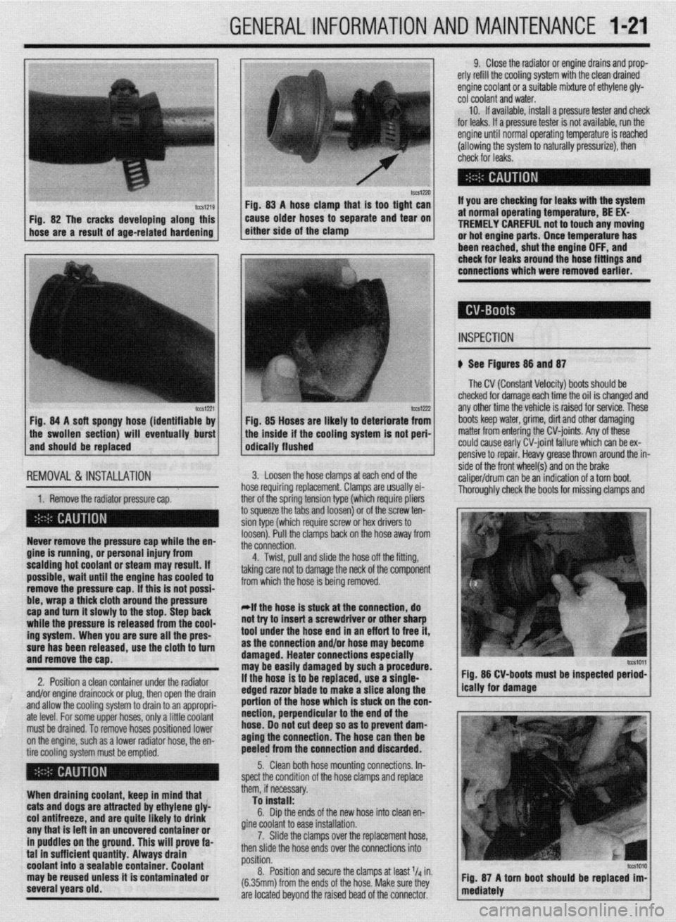
IWSIZXJ FM. 83 A hose clamn that is taa tiaht can
Fig. 82 The cracks developing along this
hose are a result of age-related hardening caise older hoses td separate and ‘iear on
either side of the clamp
lCCS1221 Fig. 84 A soft spongy hose (identifiable by
1 the swollen section) will eventually burst
and should be replaced
IEMOVAL &,INSTALLATION '
1. Remove the radiator pressure cap. her of the sorina tension tvoe (which reouire oliers
3 squeeze the 6bs and loosenj or of the’screw ten-
ion type (which require screw or hex drivers to
oosen). Pull the clamps back on the hose away from
he connection. Never remove the pressure cap while the en-
gine is running, or personal injury from
scalding hot coolant or steam may result. If
possible, wait until the engine has cooled to
remove the pressure cap. If this is not possi-
ble, wrap a thick cloth around the pressure
cap and turn it slowly to the stop. Step back
while the pressure is released from the cool-
ing system. When you are sure all the pres-
sure has been released, use the cloth to turn
and remove the cao.
2. Position a clean container under the radiator
and/or engine draincock or plug, then open the drain
and allow the cooling system to drain to an appropri-
ate level. For some upper hoses, only a little coolant
must be drained. To remove hoses positioned lower
on the engine, such as a lower radiator hose, the en-
tire cooling system must be emptied.
When draining coolant, keep in mind that
cats and dogs are attracted by ethylene gly-
col antifreeze, and are quite likely to drink
any that is left in an uncovered container or
in puddles on the ground. This will prove fa-
tal in sufficient quantity. Always drain
coolant into a sealable container. Coolant
may be reused unless it is contaminated or
several years old. 9. Close the radiator or engine drains and prop-
erly refill the cooling system with the clean drained
engine coolant or a suitable mixture of ethylene gly-
cot coolant and water.
10. If available, install a pressure tester and check
for leaks. If a pressure tester is not available, run the
engine until normal operating temperature is reached
(allowing the system to naturally pressurize), then
check for leaks.
If you are checking for leaks with the system
at normal operating temperature, BE EX-
TREMELY CAREFUL not to touch any moving
or hot engine parts. Once temperature has
been reached. shut the enaine OFF. and
Fig. 85 Hoses are likely to deteriorate from
the inside if the cooling system is not peri-
odically flushed check for leaks around the-hose fittings and
connections which were removed earlier.
INSPECTION
b See Figures 88 and 87
The CV (Constant Velocity) boots should be
checked for damage each time the oil is changed and
any other time the vehicle is raised for service. These
boots keep water, grime, dirt and other damaging
matter from entering the CV-joints. Any of these
could cause early CV-joint failure which can be ex-
pensive to repair. Heavy grease thrown around the in-
side of the front wheel(s) and on the brake
caliper/drum can be an indication of a torn boot.
Thorouahlv check the boots for missina clamos and 3. Loosen the hose clamps at each end of the
rose requiring replacement. Clamps are usually ei-
4. Twist, pull and slide the hose off the fitting,
sking care not to damage the neck of the component
rom which the hose is being removed.
*If the hose is stuck at the connection, do
lot try to insert a screwdriver or other sharp
ool under the hose end in an eff art to free it,
IS the connection and/or hose may become
lamaged. Heater connections especially
nay be easily damaged by such a procedure.
f the hose is to be replaced, use a single-
!dged razor blade to make a slice along the
lortion of the hose which is stuck on the con-
section, perpendicular to the end of the
lose. 00 not cut deep so as to prevent dam-
aging the connection. The hose can then be
keeled from the connection and discarded. Fig. 86 CV-boots must be inspected period-
5.. Clean both hose mounting connections. In-
,pect the condition of the hose clamps and replace
hem, if necessary.
To install:
6. Dip the ends of the new hose into clean en-
fine coolant to ease installation.
7. Slide the clamps over the replacement hose,
hen slide the hose ends over the connections into
rosition.
8. Position and secure the clamps at least l/d in.
6.35mm) from the ends of the hose. Make sure they
Ire located beyond the raised bead of the connector.
Page 21 of 408
l-22 GENERALINFORMATIONAND MAINTENANCE
tears. If the boot is damaged, it should be replaced
trode is to the block’s cooling passages) the cooler it
your driving is long distance, high speed travel, use a
immediately. Please refer to Section 7 for procedures.
will operate. A plug that absorbs little heat and re-
colder plug; if most of your driving is stop and go,
mains too cool will quickly accumulate deposits of
use a hotter plug. Original equipment plugs are gen-
oil and carbon since it is not hot enough to burn
erally a good compromise between the 2 styles and
them off. This leads to plug fouling and consequently
most people never have the need to change their
to misfiring. A plug that absorbs too much heat will
plugs from the factory-recommended heat range.
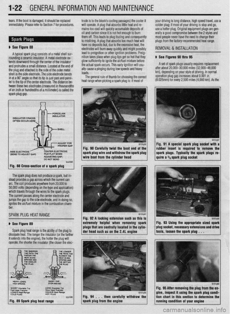
ti See Figure 88 have no deposits but, due to the excessive heat, the
,electrodes will burn away quickly and might possibly
REMOVAL &INSTALLATION
A typical spark plug consists of a metal shell sur- lead to preignition or other ignition problems. Preig-
rounding a ceramic insulator. A metal electrode ex- nition takes place when plug tips get so hot that they
ti See Figures 90 thru 95
tends downward through the center of the insulator glow sufficiently to ignite the air/fuel mixture before
and protrudes a small distance. Located at the end of the actual spark occurs. This early ignition will usu- A set of spark plugs usually requires replacement
the plug and attached to the side of the outer metal ally cause a pinging during low speeds and heavy after about 20,000-30,000 miles (32,000-48,000
shell is the side electrode. The side electrode bends loads. km), depending on your style of driving. In normal
in at a 90” angle so that its tip is just past and paral- The general rule of thumb for choosing the correct operation plug gap increases about 0.001 in.
lel to the tio of the center electrode. The distance be- heat range when picking a spark plug is: if most of (0.025mrn) for every 2,500 miles
(4,000 km). As the
tween these two electrodes (measured in thousandths
of an inch or hundredths of a millimeter) is called the
spark piug gap.
The spark plug does not produce a spark, but in-
steed provides a gap across which the current can
arc. The coil produces anywhere from 20,000 to
50,000 volts (depending on the type and application)
which travels through the wires to the spark plugs.
The current passes along the center electrode and
jumps the gap to the side electrode, and in doing so,
ignites the air/fuel mixture in the combustion charn-
ber.
SPARKPLUG HEATRANGE
ti See Figure 89
Spark plug heat range is the ability of the plug to
dissipate heat. The longer the insulator (or the farther
INSULATOR CRACKS
OFTEN OCCUR HERE
SIDE ELECTRODE ENTER ELECTRODE:
(SEND TO ADJUST GAP) FILE FLAT WHEN
ADJUSTING GAP;
DO NOT BEND
Fig. 88 Cross-section of a spark plug
it extends into the engine), the hotter the plug will
operate; the shorter the insulator (the closer the elec- Fig. 90 Carefully twist the boot end of the
I
spark plug wire and withdraw the spark plug
wire boot from the cylinder head
Fig. 92 A locking extension such as this is
extremely helpful when removing spark
plugs that are centrally located in the cyhn-
Fig. 94 . . .
then carefully withdraw the
spark plug from the engine Fig. 91 A special spark plug socket with a
rubber insert is required to remove the
spark plugs. Typically the spark plugs
re-
quire a Ya spark plug socket
Fig, 93 Using the appropriate sized spark
plug socket, necessary extensions and drive
tools, loosen the spark plug . . .
93151ptxl Fig. 95 After removing the plug from the en-
gine, inspect it using the spark plug condi-
tion chart in this section to determine the
running condition of your engine
Page 22 of 408
t
GENERALINFORMATIONAND MAINTENANCE l-23
gap increases, the plug’s voltage requirement also in-
creases. It requires a greater voltage to jump the the spark plug counterclockwise to loosen and re-
move the spark plug from the bore.
wider gap and about &o to three times as much volt-
age to fire the plug at high speeds than at idle. The
improved air/fuel ratio control of modern fuel injec-
tion combined with the higher voltage output of mod- Be sure not to use a flexible extension on the place. The click may be felt or heard, then gently pull
ern ignition systems will often allow an engine to run socket. Use of a flexible extension may allow back on the boot to assure proper contact.
.___. . _
significantly longer on a set of standard spark plugs, a shear force to be agptf’ ea to me plug.
A 12. On the 3.OL fSOHC and DOHC) and 3.5L en-
LL_ _I___ -u I_ IL-
but keep in mind that efficiency will drop as the gap shear force could break tne pug on III me
tion 3 for the installation procedure.
widens (along with fuel economy and power). cylinder head, leading to costly and frustrat-
13. If equipped, install the center cover.
When you’re removing spark plugs, work on one ing repairs.
at a time. Don’t start by removing the plug wires all at
once, because, unless you number them, they may To install:
INSPECTION & GAPPING
11. Apply a small amount of silicone dielectric
compound to the end of the spark plug lead or inside
the spark plug boot to prevent sticking, then install
the boot to the spark plug and push until it clicks into
gines, install the upper intake manifold. Refer to Sec-
,,Y” ..1111 uy”’ 1 the neaative bat&v cable and if become mixed up. Take a minute before you begin
and number the wrrpc with +sne
1. Disconnect. ~~.~
--..-., -..-.-, -..-
thevehicle has been run recently, allow the engine to
thoroughly cool.
2. If equipped, remove the center cover.
3. On the 3.OL (SOHC and DOHC) and 3.5L en-
gines, the upper intake manifold must be removed to
access the rear spark plugs. Refer to Section 3 for the
removal procedure.
4. Carefully twist the spark plug wire boot to
loosen it, then pull upward and remove the boot from
the plug. Be sure to pull on the boot and not on the
wire, otherwise the connector located inside the boot
may become separated.
5. Using compressed air, blow any water or de-
bris from the spark plug well to assure that no harm-
ful contaminants are allowed to enter the combustion
chamber when the spark plug is removed. If com-
pressed air is not available, use a raa or a brush to must be replaced.
Check the plugs for deposits and wear, If they are 7. Inspect the spark plug boot for tears or dam-
age. If.a damaged boot is found, the spark plug wire
8. Using a wire feelergauge, check and adjust
the spark plug gap. When using a gauge, the proper
size should pass between the electrodes with a slight
drag. The next larger size should not be able to pass
while the next smaller size should pass freely.
9. Carefully thread the plug into the bore by
hand. If resistance is felt before the plug is almost
completely threaded, back the plug out and begin
threading again. In small, hard to reach areas, an old
spark plug wire and boot could be used as a thread-
ing tool. The boot will hold the plug while you twist
the end of the wire and the wire is supple enough to
twist before it would allow the plug to crossthread.
Do not use the spark plug sock?
l -- K-rrA tha nhme Alwmm rarntdlv thw GL I” IlllGa”
the possibility of crossthreading and damag- lad the plug
. ..Y f..“YY. rn”Y,‘““mY*“.‘, .I**” by hand or using an old plug wire to prevent
ing the cylinder head bore.
10. Carefully tighten the spark plug. If the plug
you are installing is equipped with a crush washer,
seat the plug, then tighten about I/, turn to crush the
washer. If you are installing a tapered seat plug,
tighten the plug to specifications provided by the ve-
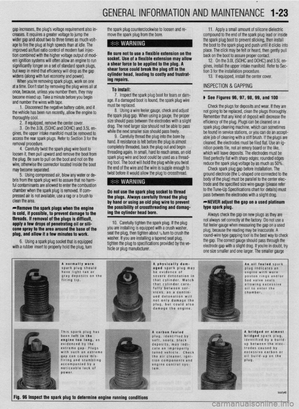
hicle or plug manufacturer. b See Figures 98, 97, 98, 99, and 100
not going to be replaced, clean the plugs thoroughly.
Remember that any kind of deposit will decrease the
efficiency of the plug. Plugs can be cleaned on a
spark plug cleaning machine, which can sometimes
be found in service stations, or you can do an accept-
able job of cleaning with a stiff brush. If the plugs are’
cleaned, the electrodes must be filed flat. Use an ig-
nition points file, not an emery board or the like,
which will leave deposits. The electrodes must be
filed perfectly flat with sharp edges; rounded edges
reduce the spark plug voltage by as much as 50%.
Check spark plug gap before installation. The
ground electrode (the L-shaped one connected to the
body of the plug) must be parallel to the center elec-
trode and the specified size wire gauge (please refer
to the Tune-Up Specifications chart for details) must
pass between the electrodes with a slight drag:
*,NEVER adjust the gap on a used platinum
. clean the area.
*Remove the spark plugs when the engine
is cold, if possible, to prevent damage to the
threads. If removal of the plugs is difficult,
apply a few drops of penetrating oil or sili-
cone spray to the area around the base of the
plug, and allow it a few minutes to work.
6. Using a spark plug socket that is equipped
with a rubber insert to properly hold the plug, turn type spark plug.
Always check the gap on new plugs as they are
not always set correctly at the factory. Do not use a
flat feeler gauge when measuring the gap on a used
plug, because the reading may be inaccurate. A
round-wire type gapping tool is the best way to check
the gap. The correct gauge should pass through the
electrode gap with a slight drag. If you’re in doubt, try
one size smaller and one laraer. The smaller aauqe
Page 23 of 408
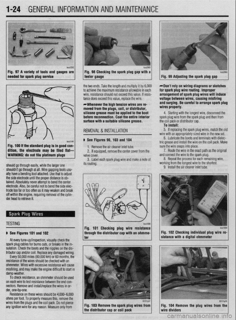
l-24 GENERALINFORMATIONAND MAINTENANCE
b%slZl2 Fig. 97 A variety of tools and gauges are
needed for spark plug service tm2903 Fig. 98 Checking the spark plug @au with a tccs2904 feeler gauge. - Fig. 99 Adjusting the spark plug gap
ig. 100 If the standard plug Is in good con-
ftlon, the electrode may be filed flat- the two ends. Take the length and multiply it by 6,000
to achieve the maximum resistance allowable in each
wire, resistance should not exceed this value. If resis-
tance does exceed this value, replace the wire.
*Whenever the high tension wires are re- ’
moved from the plugs, coil, or distributor,
silicone grease must be applied to the boot
before reconnection. Coat the entire Interior
surface with a suitable silicone grease.
REMOVAL &INSTALLATION
# See Figures 90,103 and 104
1. Remove the air cleaner inlet tube.
2. If eouiooed, remove the center cover from the
WARNING: do not file platinum plugs
valve covei.
3. Label each spark plug wire and make a note of
should go through easily, while the larger one its routing.
I’ shouldn’t go through at all. Wire gapping tools usu-
ally have a bending tool attached. Use that to adjust
the side electrode until the proper distance is ob-
tained. Absolutely never attempt to bend the center
electrode. Also, be careful not to bend the side elec- *Don’t rely on wiring diagrams or sketches
for spark plug wire routing. Improper
arrangement of spark plug wires will induce
voltage between wires, causing misfiring
and surging. Be careful to arrange spark plug
wires properly.
4. Starting with the longest wire, disconnect the
spark plug wire from the spark plug and then from
the coil pack or distributor cap.
To install:
5. If replacing the spark plug wires, match the olc
wire with an appropriately sized wire in the new set.
6. Lubricate the boots and terminals with dielec-
tric grease and install the wire on the coil pack. Make
sure the wire snaps into place.
a 7. Route the wire in the exact path as the original
nd connect the wire to the spark plug.
8. Repeat the process for each remaining wire,
iorking from the longest wire to the shortest.
9. Install the air cleaner inlet tube.
trode too far or too often as it may weaken and break
off within the engine, requiring removal of the cylin-
der head to retrieve it.
TESTING
# See Figures 191 and 102
At every tune-up/inspection, visually check the
spark plug cables for burns cuts, or breaks in the in-
sulation. Check the boots and the nipples on the dis-
tributor cap and/or coil. Replace any damaged wiring.
Every 50,000 miles (80,000 km) or 60 months, the
resistance of the wires should be checked with an
ohmmeter. Wires with excessive resistance will cause
misfiring, and may make the engine difficult to start in
damp weather.
To check resistance, an ohmmeter should be used ’
on each wire to test resistance between the end con-
nectors. Remove and install/replace the wires in or- ’
der, one-by-one.
Resistance on these wires should be 4,000-6,000
ohms per foot. To properly measure this, remove the
wires from the plugs and the coil pack. Do not pierce
any ignition wire for any reason. Measure only from Fig. 103 Remove the spark plug wires from
tcG1009 Fig. 102 Checking individual plug wire re-
sistance with a digital ohmmeter
Fig. 104 Remove the plug wires from the
wire dividers
Page 49 of 408
.~ P.X I_ - “, .- I .-., IS ” .~.I .r
2-2 ENGINE ELECTRICAL
nn
ity and trouble: shooting electrical circuits,
please refer to Section 6 of this manual.
I
The ignition system on the 1.5L, 1993-96 1.8L,
2.OL SOHC, 1994-98 2.4L SOHC, 3.OL SOHC, and
3.5L engines uses a pointless type distributor, whose
advance mechanism is controlled by the Engine Con-
trol Unit (ECU). On the 1.5L, 1.8L, 2.4L and 3.5L en-
gines, the distributor houses a built in ignition coil
and ignition power transistor. The 2.8L SOHC and
3.OL SOHC engines utilize a separate coil and tran-
sister assemblv.
When the ignition switch is turned ON, battery
voltage is applied to the ignition coil primary winding.
As the shaft of the distributor rotates, signals are
transmitted from the oowertrain control module to the
9105zp11 Fig. 1 This spark tester looks iust like a
Fiu. 2 This spark tester has an adjustable
spark plug, attach the clip to ground and air-gap for measuring spark strength and
crank the engine to check for spark testing different voltage ignition systems
.
ignition power trar rsistor. These signals activate the
power transistor to cause ignition coil primary wind-
ing current flow from the ignition coil negative termi-
nal through the power transistor to ground repeatedly.
This interruption induces high voltage in the ignition
coil secondarv windinas, which is diverted throuah
the distributor, spark plug cable and spark plug 6
ground, thus causing ignition in each cylinder.
I
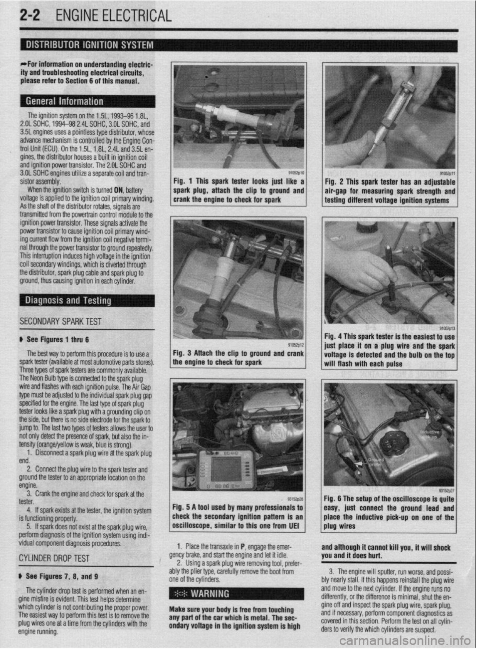
SECONDARYSPARKTEST l;h.4-
! ,L ".~
'$ >,%
If See Figures 1 thru 6
91rJszp12 Fig. 4 This spark tester is the easiest to use
iust alace it on a plug wire and the spark
The best way to perform this procedure is to use a Fig. 3 Attach the clip to ground and crank
spark tester (available at most automotive parts stores). the engine to check for spark
I I voltage is detected and the bulb on the tof
-. will flash with each pulse
I nree types ot spark testers are commonly available.
The Neon Bulb type is connected to the spark plug
wire and flashes with each ignition pulse. The Air Gap
type must be adjusted to the individual spark plug gap
specified for the engine. The last type of spark plug
tester looks like a spark plug with a grounding clip on
the side, but there is no side electrode for the spark to
jump to. The last two types of testers allows the user to
not only detect the presence of spark, but also the in-
tensity (orange/yellow is weak, blue is strong).
1. Disconnect a spark plug wire at the spark plug
end.
2. Connect the plug wire to the spark tester and
ground the tester to an appropriate location on the
engine.
3. Crank the engine and check for spark at the
tester.
4. If spark exists at the tester, the ignition system
is functioning properly.
5. If spark does not exist at the spark plug wire,
perform diagnosis of the ignition system using indi-
vidual component diagnosis procedures,
CYLINDER DROPTEST
p See Figures 7, 8, and 9
The cylinder drop test is performed when an en-
gine misfire is evident. This test helps determine
which cylinder is not contributing the proper power.
The easiest way to perform this test is to remove the
plug wires one at a time from the cylinders with the
engine running. 1. Place the transaxle in P, engage the emer-
gency brake, and start the engine and let it idle.
2. Using a spark plug wire removing tool, prefer-
ably the plier type, carefully remove the boot from
one of the cylinders.
i ’
Make sure your body is free from touching
any part of the car which is metal. The sec-
ondary voltage in the ignition system is high and although it cannot kill you, it will shock
you and it does hurt.
3. The engine will sputter, run worse, and possi-
bly nearly stall. If this happens reinstall the plug wire
and move to the next cylinder. If the engine runs no
differently, or the difference is minimal, shut the en-
gine off and inspect the spark plug wire, spark plug,
and if necessary, perform component diagnostics as
covered in this section. Perform the test on all cylin-
ders to verify the which cylinders are suspect.
Page 50 of 408
ENGINEELECTRICAL 2-3
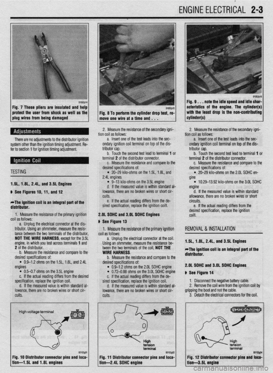
91c6zp16 Fig. 9. . . note the idle speed and idle char-
acteristics of the engine. The cylinder(s)
with the least drag is the non-contributing
cyltnder(s) -
1
There are no adjustments to the distributor ignition
system other than the ignition timing adjustment. Re-
fer to section 1 for ignition timing adjustment.
TESTING
1.5L, 1.8L, 2.41, and 3.51 Englnes
u See Figures 10, 11, and 12
*The ignition cog is an integral part of the
distributor.
1. Measure the resistance of the primary ignition
coil as follows:
a. Unplug the electrical connector at the dis-
tributor. Using an ohmmeter, measure the resis-
tance between the two terminals of the distributor,
NOT THE WIRE HARNESS, except for the 3.5L
engine, in which you test across terminals 1 and
2 of the distributor.
b. Measure the resistance and compare to the
desired specifications of:
l 0.9-1.2 ohms on the 1.5L, 1.8L, and 2.4L
engines
l 0.5-0.7 ohms on the 35L engine
c. If the actual reading differs from the desired
specification, replace the ignition coil.
d. If the measured value is within standard al-
lowance, there are no broken wires or short cir-
cuits. 2. Measure the resistance of the secondary igni-
desired specifications of: tion coil as follows:
l 21329 kilo-ohms on the 1.5L, 1.8L, and
2.4L engines a. Insert one of the test leads into the sec-
ondary ignition coil terminal on top of the dis-
l 9-13 kilo-ohms on the 3.5L engine tributor cap.
d. If the measured value is within standard al- b. Touch the second test lead to terminal 1 or
terminal 2 of the distributor connector.
lowance, there are no broken wires or short cir-
cuits. c. Measure the resistance and comnare to the
e. If the actual reading differs from the de
sired specification, replace the ignition coi!l.
2.OL SOHC and 3.OL SOHC Engines
# See Figure 13
1. Measure the resistance of the primary ignition
coil as follows:
a. Unplug the electrical connector at the coil.
Using an ohmmeter, measure the resistance be-
tween the two terminals of the coil, NOT THE
WIRE HARNESS.
b. Measure the resistance and compare to the
desired specifications of:
l 0.9-1.2 ohms on the 2.OL SOHC engine l 0.72-0.88 ohms on the 3.OL SOHC engine
c. If the actual reading differs from the de-
sired specification, replace the ignition coil.
d. If the measured value is within standard al-
lowance, there are no broken wires or short cir-
cuits. 2.
desired specifications of: Measure the resistance of the secondary igni-
tion coil as follows:
l 20-29 kilo-ohms on the 2.OL SOHC en-
gine a. Insert one of the test leads into the sec-
ondary ignition coil terminal on top of the dis-
l 10.29-13.92 kilo-ohms on the 3.01 SOHC tributor cap.
engine b. Touch the second test lead to terminal 1 or
terminal 2 of the distributor connector.
d. If the measured value is within standard
allowance, there are no broken wires or short c. Measure the resistance and comoare to the
circuits.
e. If the actual reading differs from the
desired specification, replace the ignition
coi!l.
REMOVAL&INSTALLATION
1.5L, 1.8L, 2.4L, and 3.5L Engines
*The ignition coil is an tntegral part of the
distributor.
2.OL SOHC and 3.OL SDHC Engines
u See Figure 14
1. Disconnect the negative battery cable.
2. Remove the coil wire from the ignition coil by
gripping the boot and not the cable.
3. Detach the electrical connectors for the coil.
High voltage terminal -r
I Q3 ‘I u,
/ - Blm/ I L tflgn
tension
terminal
,
3=%@ @l&M Fig. IO Distributor connector pins and loca-
Fig. 11 Distributor connector pins and loca- Fig. 12 Dlstrfbufor connector plus and loca-
tiou-l.LL and 1.8L engines
lion-2.4L SOHC engtne tio&.5L engine
Page 53 of 408
2-6 ENGINEELECTRICAL
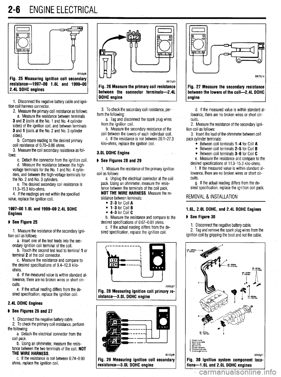
Fig. 26 Measuring ignition coil secondary
resistance-1997-00 1.8L and 1994-00
2.4L SOHC engines
1. Disconnect the negative battery cable and igni-
tion coil harness connector. 89572914
89572g13
Fig. 28 Measure the primary coil resistance Fig. 27 Measure the secondary resistance
between the connector terminals-2.4L between the towers of the coil-2.4L DOHC
DOHC enaine engine
3. To check the secondary coil resistance, per-
. .
term the tollowmg:
a. Tag and disconnect the spark plug wires
from the ignition coil.
b. Measure the secondary resistance of the
coil between the towers of each individual coil.
c. If the resistance is not between 20.1-27.3
kilo-ohms, replace the ignition coil. 2. Measure the primary coil resistance as follows:
a. Measure the resistance between terminals
3 and 2 (coils at the No. 1 and No. 4 cylinder
sides) of the ignition coil, and between terminals
3 and 1 (coils at the No. 2 and No. 3 cylinder
sides).
b. Compare reading to the desired primary
coil resistance of 0.70-0.86 ohms.
3. Measure the coil secondary resistance as fol-
lows: 3.OL DOHC Engine
c. Detach the connector from the ignition coil.
d. Measure the resistance between the high-
voltage terminals for the No. 1 and No. 4 cylin-
ders, and between the high-voltage terminals for
the No. 2 and No. 3 cylinders.
e. The desired secondary coil resistance is
11.3-15.3 kilo-ohms.
4. If the readings are not within the specified
value, replace the ignition coil.
1997-00 1.8L and 1999-00 2.4L SOHC
Engines
+ See Figure 25 6 See Figures 28 and 29
1. Measure the resistance of the primary ignition
coil as follows:
a. Unplug the electrical connector at the coil
pack. Using an ohmmeter, measure the resis-
tance between the terminals of the coil pack,
NOT THE WIRE HARNESS. Measure the re-
sistance between terminals:
l 2-3 for Coil A l l-3 for Coil B l 4-3 for Coil C
b. Measure the resistance and compare to the
desired specifications of 0.67-0.81 ohms.
1. Measure the resistance of the secondarv iani-
tion coil as follows: , -
a. Insert one of the test leads into the sec-
ondary ignition coil terminal of the coil.
b. Touch the second test lead to terminal 1 or
terminal 2 of the coil connector.
c. Measure the resistance and compare to
the desired specifications of 9.4-12.8 kilo-
ohms.
d. If the measured value is within standard al-
lowance, there are no broken wires or short cir-
cuits.
e. If the actual reading differs from the de-
sired specification, replace the ignition coil.
2.4L DDHC Engines
# See Figures 26 and 27
1. Disconnect the negative battery cable.
2. To check the primary coil resistance, perform
the following:
a. Detach the electrical connector from the
coil pack.
b. Using an ohmmeter, measure the resis-
tance between the two terminals of the coil, NOT
THE WIRE HARNESS.
c. If the resistance is not between 0.74-0.90
ohms, replace the ignition coil. c. If the actual reading differs from the de-
sired specification, replace the ignition coil.
Fig. 28 Measuring ignition coil primary re-
sistance-3.01 DOHC engine
Fig. 29 Measuring ignition coil secondary
resistance-3.01 DOHC enaine d. If the measured value is within standard al-
lowance, there are no broken wires or short cir-
cuits.
2. Measure the resistance of the secondary igni-
tion coil as follows:
3. Insert the lead of the ohmmeter between coil
pack cylinder terminals:
l Between coil terminals l-4 for Co11 A l Between coil terminals 2-5 for Coil B l Between coil terminals 3-6 for Coil C
e. Measure the resistance and compare to the
desired specifications of 11.3-l 5.3 kilo-ohms.
f. If the measured value is within standard al-
lowance, there are no broken wires or short cir-
cuits.
g. If the actual reading differs from the de-
sired specification, replace the ignition coil pack.
REMOVAL&INSTALLATION
1.6L, 2.OL DOHC, and 2.4L DOHC Engines
# See Figure 30
1. Disconnect the negative battery cable.
2. Tag and remove the spark plug wires from the
ignition coil by gripping the boot and not the cable.
I
~::::L “1
I cemer Cwer
2 Scabpiwcabk
3 SPaark piug
I lgnlllancoll
5 Powertran3lrtor
6 ThrotflsDcnv*w
I Crankangle lmsm
93152g11
Fig. 30 Ignition system component loca-
lions-l .6L and 2.OL DOHC engines