2022 TOYOTA SUPRA brake light
[x] Cancel search: brake lightPage 13 of 498

11
1
1-1. NOTES
NOTES
or the driver's behaviour.
These include, for example:
• Status reports relating to the
vehicle and its individual compo-
nents, for example wheel speed,
wheel circumferential velocity,
deceleration, lateral accelera-
tion, fastened seat belts.
• Ambient conditions, for example
temperature, rain sensor signals.
The data is processed within the
vehicle and is usually transient. It is
only saved for longer than the oper-
ating period if it is required in order
to perform services agreed with the
customer.
Electronic parts, for example con-
trol devices and vehicle keys, con-
tain components for storing
technical informat ion. Information
about the vehicle's condition, com-
ponent use and wear, maintenance
requirements, events or errors can
be stored temporarily or perma-
nently.
This information generally docu-
ments the condition of a compo-
nent, a module, a system or the
vehicle surroundings, including:
• Operating states of system com-
ponents, for examp le fill levels,
tyre inflation pr essure, battery
status.
• Malfunctions and faults of impor-
tant system components, for
example lights and brakes.
• Responses of the vehicle to par-
ticular driving situations, for
example triggering of an airbag,
activation of th e drive stability
control systems.
• Information on vehicle-damag-
ing events.
The data is required so that the
control units can perform their func-
tions. It is also used for detecting
and rectifying malfunctions, as well
as to optimise vehicle functions.
Most of this data is transient and is
only processed within the vehicle
itself. Only a small proportion of the
data is stored in event or error
memories in response to specific
circumstances.
Convenience functions, such as
seat, climate or light settings, make
every journey even more pleasant.
The personal settings for these
functions can be saved in a profile
within the vehicle and retrieved on
request, for example if the settings
have been changed by another
driver. Depending on the equip-
ment, these profiles can be saved
in the vehicle manufacturer's
secure data systems. When the
driver changes vehicle, these
saved profiles can simply be
applied to a different vehicle.
The vehicle settings saved in the
vehicle profile can be changed or
deleted at any time.
Electronic components
Personal settings
Page 15 of 498

13
1
1-1. NOTES
NOTES
only use this data for the purposes
of performing the service or repair
order in question. This prevents
work from being duplicated unnec-
essarily on the vehicle, for exam-
ple.
The data logs the technical condi-
tions of the vehicle and helps in
locating errors, complying with war-
ranty obligations and improving
quality.
To ensure product quality and the
development of new products, data
on the usage of individual compo-
nents and systems may be read
out, for example lights, brakes,
power windows, displays. This data
helps the vehicle manufacturer to
optimise the design of components
and systems. Data analysis also
provides the basis for Technical
Campaigns and statutory recalls.
Furthermore, the manufacturer has
product monitoring obligations to
meet in line with product liability
law. To fulfil these obligations, the
vehicle manufacturer requires tech-
nical data from the vehicle.
Data from the vehicle can also be
used to check customer warranty
claims. If goodw ill or warranty
claims are asserted, the read out
data is transferred to the vehicle
manufacturer to resolve the claims
promptly.
Error and event memories in the
vehicle can be reset when any
authorized Toyota retailer or Toyota
authorized repairer, or any reliable
repairer performs repair or servic-
ing work.
Data transferred to the vehicle
manufacturer for the purposes of
ensuring product quality or optimis-
ing service processes can be pre-
vented upon request.
According to current law, the vehi-
cle manufacturer is obliged to pro-
vide the authorities with any data it
has stored. Data is provided to the
extent required and on a
case-by-case basis, for example to
investigate a criminal offence.
The current law also gives state
bodies authorisation to read out
data from the vehicle themselves
for individual cases. This could
include reading out data from the
airbag control device to shed light
on the circumstances of an acci-
dent, for example.
In the context of legal obligations
within the EU, certain vehicle con-
sumption data, so-called OBFCM
data, are transmitted to the EU
Ensuring product quality
Goodwill and warr anty claims
Control over data
Legal requirements regard-
ing data disclosure
Page 32 of 498

302-1. QUICK REFERENCE
1Wipers
2 Instrument cluster
3 Turn indicator, high-beam head-
lights
4 Light switch element
Indicator and warning lamps can
illuminate in a variety of combina-
tions and colours.
When the engine starts or the
standby state is switched on, the
functionality of some lights is briefly
checked.
1 Exterior mirrors
2 Power window switches
3 Central locking system
4 Unlocking the boot lid
1 Selector lever
2 Controller
3 Auto Start & Stop cancel button
4 Sport mode switch
5 Park Assistant button
6 VSC OFF button
7 Toyota Supra Safety button
8 Parking brake
Toyota Supra Command brings
together the functions of a number
of switches. These functions can be
operated using the Controller and,
depending on the equipment ver-
sion, the touchscreen.
Displays and controls
Around the steering wheel
Indicator and warning lamps
Driver's door
1
2
3
4
321
4
Switch cluster
Toyota Supra Command
Principle
Page 50 of 498

483-1. CONTROLS
13 Horn, entire area
14 To release the bonnet
P. 3 2 1
15 Unlocking the boot lid P.91
1 Control Display P.59
2 Hazard warning lights
P. 3 5 2
3 Ventilation P.266
4 Glove box P.274
5 Radio/multimedia, see Naviga-
tion system Owner's manual
6 Automatic air conditioning P.261
7 Controller with buttons P.60,
P. 6 1
8 Sport mode switch P.160
SPORT drive mode
Toyota Supra Safety P.205
Auto Start/Stop P.145
Parking Sensors P.50
Rear-view camera P.253
RCTA (Rear cross traffic alert)
function P.256
Park Assistant P.50
Vehicle Stability Control,
VSC P.229
9 Parking brake P.148
10 Automatic transmission selector
lever P.154
Around the centre console
1
4
23
5
6
7
89
10
11
Page 91 of 498

89
3
3-1. CONTROLS
CONTROLS
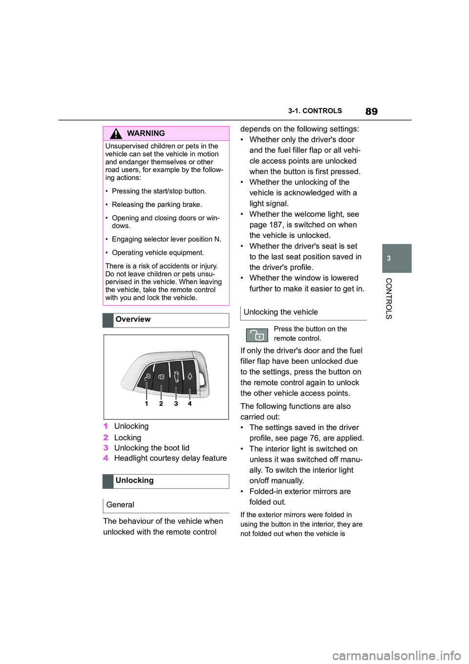
1 Unlocking
2 Locking
3 Unlocking the boot lid
4 Headlight courtesy delay feature
The behaviour of the vehicle when
unlocked with the remote control
depends on the following settings:
• Whether only the driver's door
and the fuel filler flap or all vehi-
cle access poin ts are unlocked
when the button is first pressed.
• Whether the unlocking of the
vehicle is acknowledged with a
light signal.
• Whether the welcome light, see
page 187, is switched on when
the vehicle is unlocked.
• Whether the driver's seat is set
to the last seat position saved in
the driver's profile.
• Whether the window is lowered
further to make it easier to get in.
If only the driver's door and the fuel
filler flap have been unlocked due
to the settings, press the button on
the remote control again to unlock
the other vehicle access points.
The following functions are also
carried out:
• The settings saved in the driver
profile, see page 76, are applied.
• The interior light is switched on
unless it was switched off manu-
ally. To switch the interior light
on/off manually.
• Folded-in exterior mirrors are
folded out.
If the exterior mirrors were folded in
using the button in the interior, they are
not folded out when the vehicle is
WA R N I N G
Unsupervised children or pets in the
vehicle can set the vehicle in motion
and endanger themselves or other road users, for example by the follow-
ing actions:
• Pressing the start/stop button.
• Releasing the parking brake.
• Opening and closing doors or win-
dows.
• Engaging selector lever position N.
• Operating vehicle equipment.
There is a risk of accidents or injury.
Do not leave children or pets unsu- pervised in the vehicle. When leaving
the vehicle, take the remote control
with you and lock the vehicle.
Overview
Unlocking
General
Unlocking the vehicle
Press the button on the
remote control.
Page 124 of 498

1223-1. CONTROLS
WA R N I N G
The seat belts are designed to protect
persons of average adult height and
weight. A child which is 150 cm or
shorter should be sat in an appropri- ately sized child restraint system,
such as a Toyota genuine child
restraint system. Do not allow a child to be unrestrained in the vehicle while
it is moving, as doing so is extremely
dangerous.
WA R N I N G
Never leave a child unattended in the
vehicle.
When parking the vehicle, turn the
engine switch off, exit the vehicle with
the child and lock the doors. Even if it
is just for a short time, leaving a child in the vehicle can be extremely dan-
gerous for the following reasons:
●When the vehicle is parked under
direct sunlight, the temperature
inside the vehicle can increase to over 50°C, even in winter. In this sit-
uation, occupants may suffer from
dehydration or heatstroke.
●If a switch is operated accidentally,
it may lead to unexpected injuries.
●Do not allow a child to open and
close the doors. When closing a door, be careful so that the child’s
hands and feet to not get caught in
the door.
●Do not allow a child to put their head or limbs out of the door win-
dow and be sure that they are clear
of the window before operating the power window switch.
Important considerations
Safety notes
WA R N I N G
Unsupervised children or pets in the vehicle can set the vehicle in motion
and endanger themselves or other
road users, for example by the follow- ing actions:
●Pressing the start/stop button.
●Release the parking brake.
●Opening and closing doors or win-
dows.
●Engaging selector lever position N.
●Operating vehicle equipment.
There is a risk of accidents or injury.
Do not leave children or pets unsu- pervised in the vehicle. When leaving
the vehicle, take the remote control
with you and lock the vehicle.
WA R N I N G
Hot vehicles can have fatal conse-
quences, in particular for children and
pets. There is a risk of injury or even death. Do not leave anyone unsuper-
vised in the vehicle, especially chil-
dren and pets.
Page 147 of 498

145
3
3-1. CONTROLS
CONTROLS
3 Releasing the parking brake.
4 Drive off.
The Auto Start/Stop helps you to
save fuel. The system switches the
engine off when stationary, for
example in congestion or at traffic
lights. The drive-ready state
remains switched on. For driving
off, the engine starts automatically.
Each time the engine is started via
the start/stop button, the Auto
Start/Stop is switched to standby.
The function is activated from a
speed of around 5 km/h, approxi-
mately 3 mph.
Depending on selected drive mode,
see page 160, the system is acti-
vated or deactivated automatically.
The engine is automatically shut
down when stationary under the fol-
lowing conditions:
Selector lever in selector lever
position D.
Brake pedal remains pressed
while the vehicle is at a standstill.
Driver's seat belt buckled or
driver's door closed.
If the engine was not switched off
automatically when the vehicle
came to a stop, it can be switched
off manually:
Rapidly press the brake pedal
from the current position.
Engage selector lever position P.
If all the operating requirements
have been met, the engine is
stopped.
The air flow rate of the air condi-
tioning system is reduced when the
engine is not running.
■General
The engine is not shut down auto-
matically in the following situations:
Auto Start/Stop
Principle
General
Stopping the engine
Operating requirements
Manual engine stop
Air conditioning system when the
vehicle is parked
Displays in the instrument cluster
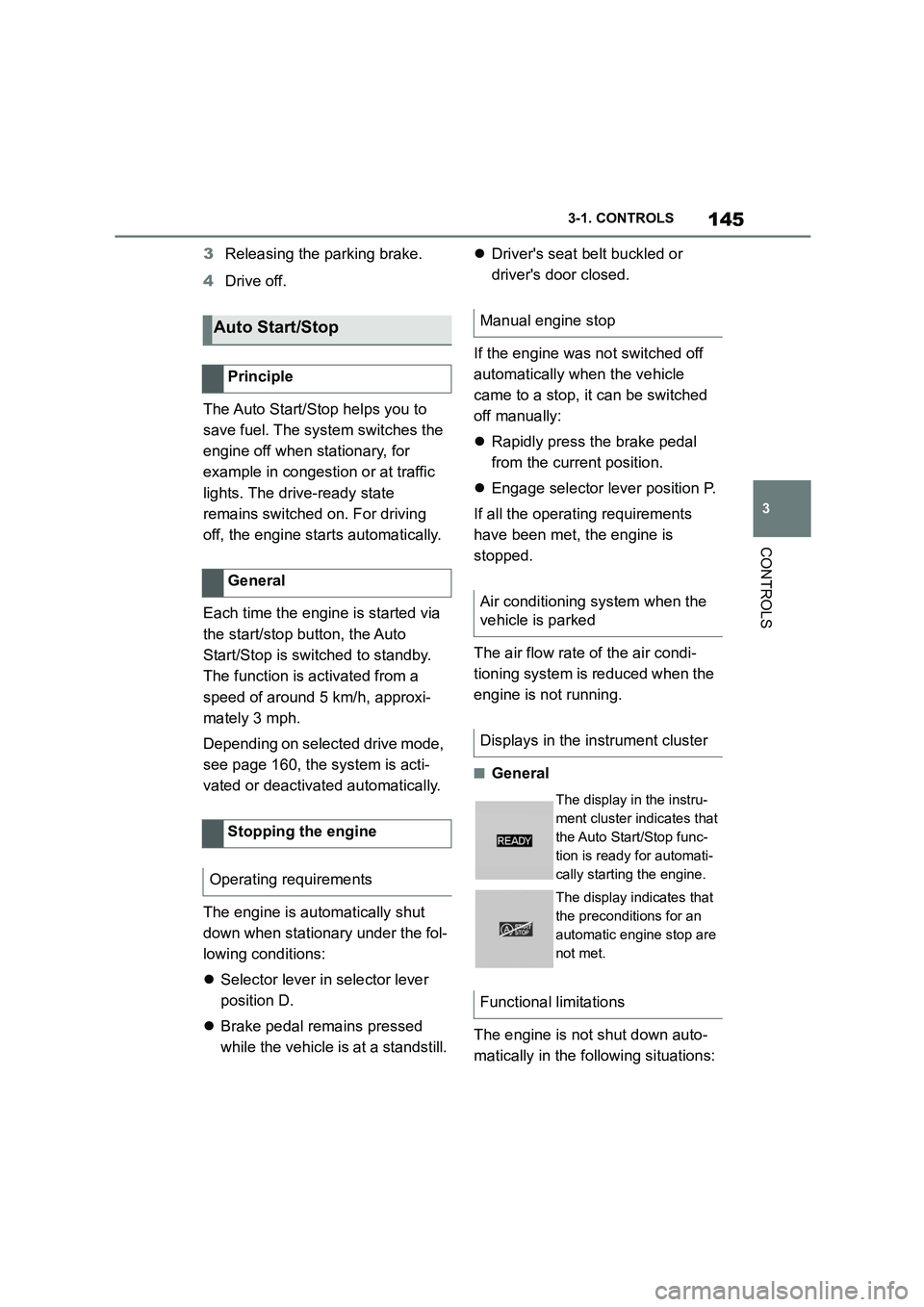
The display in the instru-
ment cluster indicates that
the Auto Start/Stop func-
tion is ready for automati-
cally starting the engine.
The display indicates that
the preconditions for an
automatic engine stop are
not met.
Functional limitations
Page 151 of 498

149
3
3-1. CONTROLS
CONTROLS
■General
Use during the journey serves as
an emergency brake.
Pull and hold the switch. Vehicle
brakes strongly for as long as the
switch is pulled.
A vehicle message is shown.
If the vehicle is braked to approxi-
mately 3 km/h, 2 mph, the parking
brake is engaged.
1 Switch on drive-ready state.
2 Press the switch with the
brake pedal depressed or selec-
tor lever position P engaged.
LED and indicator lamp turn off.
The parking brake is released.
The parking brake is automatically
released on driving off.
LED and indicator lamp turn off.
If the parking brake fails or malfunc-
tions:
After getting out, secure the vehicle
to prevent it from rolling away, for
example with a chock.
To restore parking brake functional-
ity after a power failure:
1 Switch on standby state.
2 Pull the switch with the
brake pedal depressed or selec-
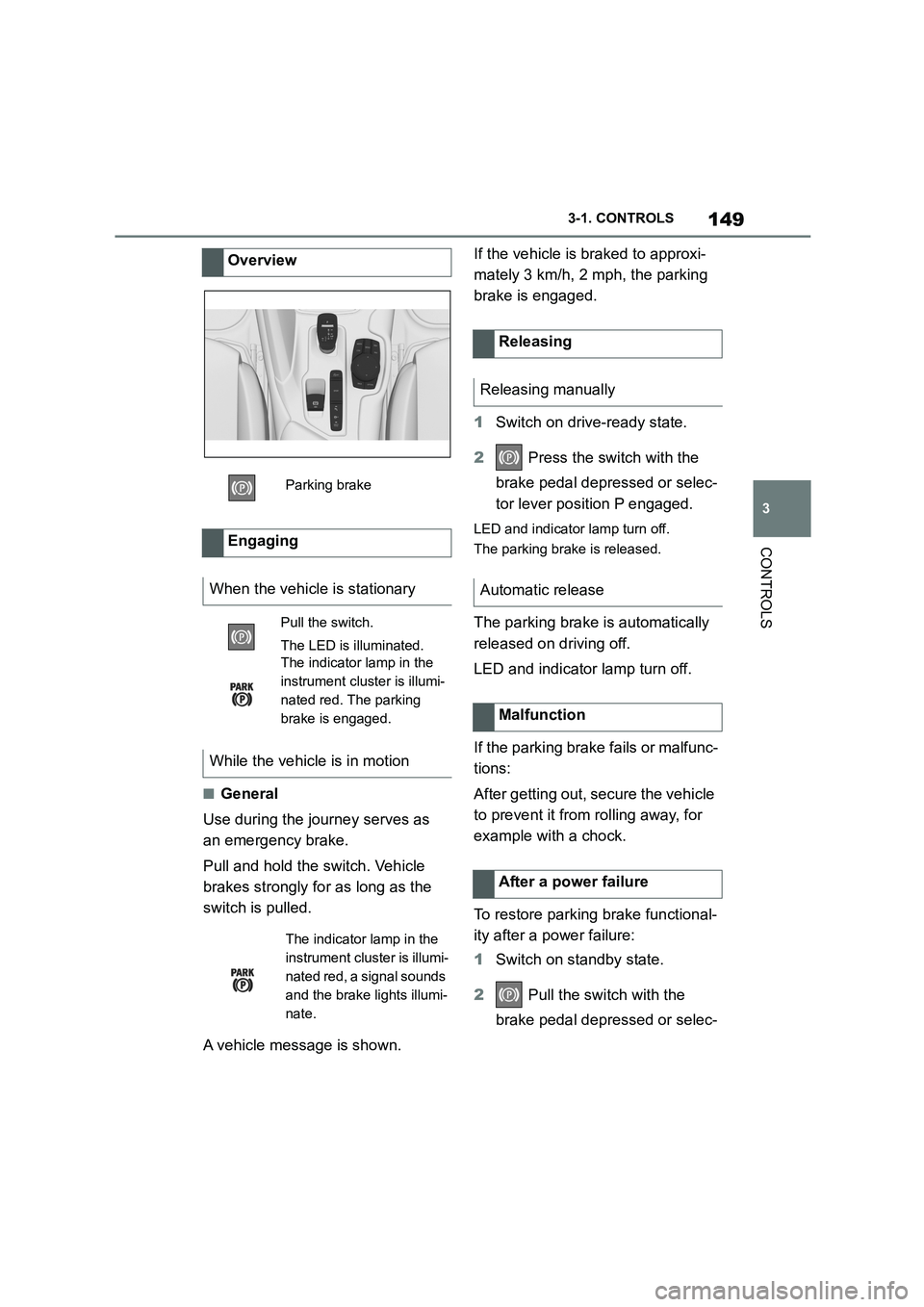
Overview
Parking brake
Engaging
When the vehicle is stationary
Pull the switch.
The LED is illuminated.
The indicator lamp in the
instrument cluster is illumi-
nated red. The parking
brake is engaged.
While the vehicle is in motion
The indicator lamp in the
instrument cluster is illumi-
nated red, a signal sounds
and the brake lights illumi-
nate.
Releasing
Releasing manually
Automatic release
Malfunction
After a power failure