Page 302 of 498
3005-1. MOBILITY
check the tyre inflation pressure.
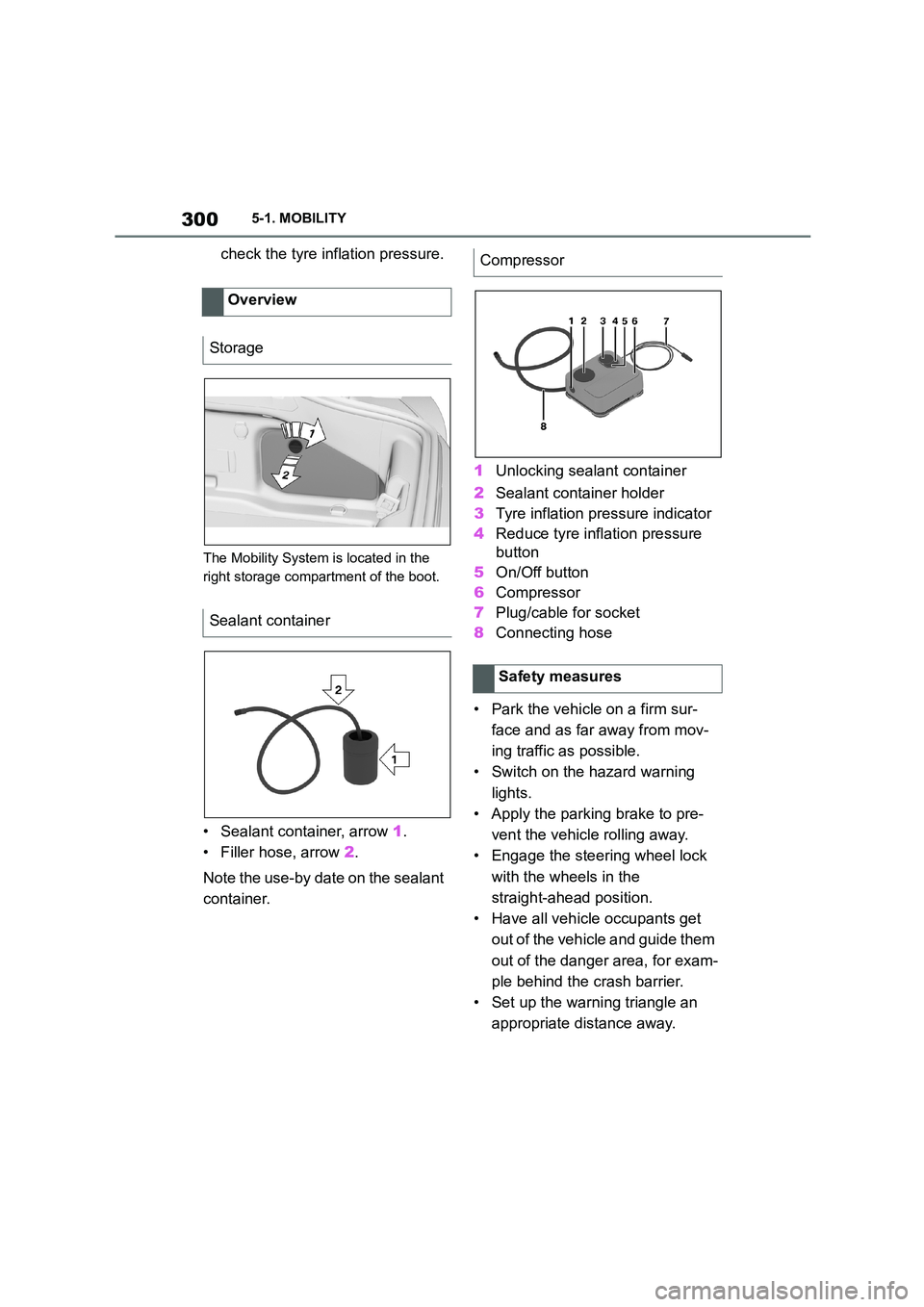
The Mobility System is located in the
right storage compartment of the boot.
• Sealant container, arrow 1.
• Filler hose, arrow 2.
Note the use-by date on the sealant
container.
1 Unlocking sealant container
2 Sealant container holder
3 Tyre inflation pressure indicator
4 Reduce tyre inflation pressure
button
5 On/Off button
6 Compressor
7 Plug/cable for socket
8 Connecting hose
• Park the vehicle on a firm sur-
face and as far away from mov-
ing traffic as possible.
• Switch on the hazard warning
lights.
• Apply the parking brake to pre-
vent the vehicle rolling away.
• Engage the steering wheel lock
with the wheels in the
straight-ahead position.
• Have all vehicle occupants get
out of the vehicle and guide them
out of the danger area, for exam-
ple behind the crash barrier.
• Set up the warning triangle an
appropriate distance away.
Overview
Storage
Sealant container
Compressor
Safety measures
Page 317 of 498
315
5
5-1. MOBILITY
MOBILITY
cial coding. The bolts can only be
released with the adapter that
matches the coding.
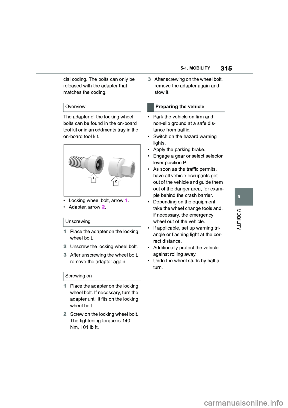
The adapter of the locking wheel
bolts can be found in the on-board
tool kit or in an oddments tray in the
on-board tool kit.
• Locking wheel bolt, arrow 1.
• Adapter, arrow 2.
1 Place the adapter on the locking
wheel bolt.
2 Unscrew the locking wheel bolt.
3 After unscrewing the wheel bolt,
remove the adapter again.
1 Place the adapter on the locking
wheel bolt. If necessary, turn the
adapter until it fi ts on the locking
wheel bolt.
2 Screw on the locking wheel bolt.
The tightening torque is 140
Nm, 101 lb ft.
3 After screwing on the wheel bolt,
remove the adapter again and
stow it.
• Park the vehicle on firm and
non-slip ground at a safe dis-
tance from traffic.
• Switch on the hazard warning
lights.
• Apply the parking brake.
• Engage a gear or select selector
lever position P.
• As soon as the traffic permits,
have all vehicle occupants get
out of the vehicle and guide them
out of the danger area, for exam-
ple behind the crash barrier.
• Depending on the equipment,
take the wheel change tools and,
if necessary, the emergency
wheel out of the vehicle.
• If applicable, set up warning tri-
angle or flashing light at the cor-
rect distance.
• Additionally protect the vehicle
against rolling away.
• Undo the wheel studs by half a
turn.
Overview
Unscrewing
Screwing on
Preparing the vehicle
Page 336 of 498
3345-1. MOBILITY
Your vehicle needs to be serviced according to the normal maintenance
schedule.
Maintenance operations:
I = Inspect, correct or replace as necessary
R = Replace, change or lubricate
Scheduled maintenance (except for Europe and
Australia)
Perform maintenance by the schedule as follows:
Maintenance schedule requirements
Maintenance schedule (except for Korea, Mexico and South
Africa)
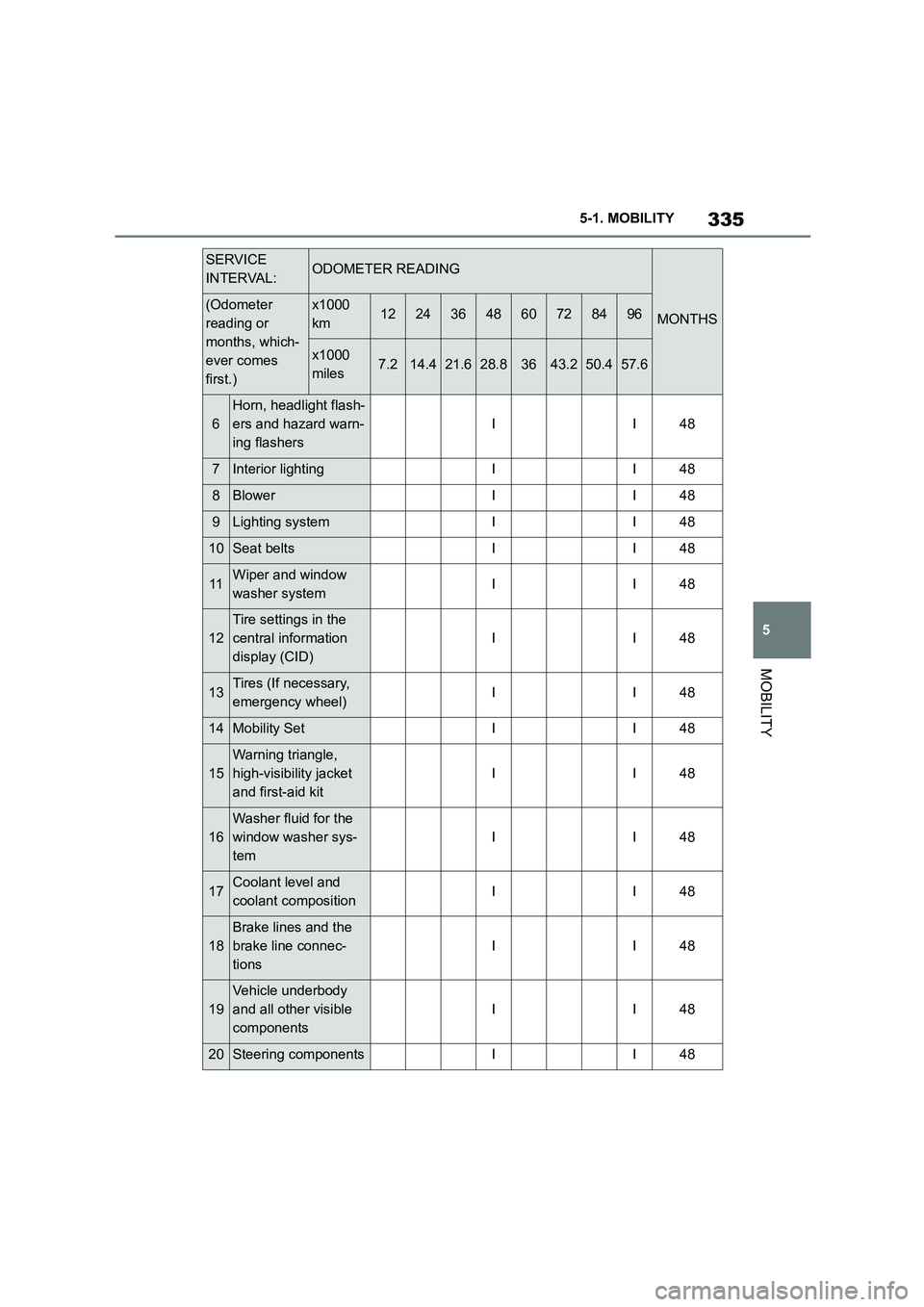
SERVICE
INTERVAL:ODOMETER READING
MONTHS(Odometer
reading or
months, which-
ever comes
first.)
x1000
km1224364860728496
x1000
miles7.214.421.628.83643.250.457.6
BASIC ENGINE COMPONENTS
1
Engine oil (Include
engine oil filter)
<>
RRRRRRRR12
IGNITION SYSTEM
2Spark plugsRRRR24
FUEL AND EMISSION CONTROL SYSTEMS
3Air filterRRRR24
CHASSIS AND BODY
4Brake padsReplace when the brake warning light
appears.-
5Brake fluidFirst replace at 36 months, then replace at every 24
months.
Page 337 of 498
335
5
5-1. MOBILITY
MOBILITY
6
Horn, headlight flash-
ers and hazard warn-
ing flashers
II48
7Interior lightingII48
8BlowerII48
9Lighting systemII48
10Seat beltsII48
11Wiper and window
washer systemII48
12
Tire settings in the
central information
display (CID)
II48
13Tires (If necessary,
emergency wheel)II48
14Mobility SetII48
15
Warning triangle,
high-visibility jacket
and first-aid kit
II48
16
Washer fluid for the
window washer sys-
tem
II48
17Coolant level and
coolant compositionII48
18
Brake lines and the
brake line connec-
tions
II48
19
Vehicle underbody
and all other visible
components
II48
20Steering componentsII48
SERVICE
INTERVAL:ODOMETER READING
MONTHS(Odometer
reading or
months, which-
ever comes
first.)
x1000
km1224364860728496
x1000
miles7.214.421.628.83643.250.457.6
Page 339 of 498
337
5
5-1. MOBILITY
MOBILITY
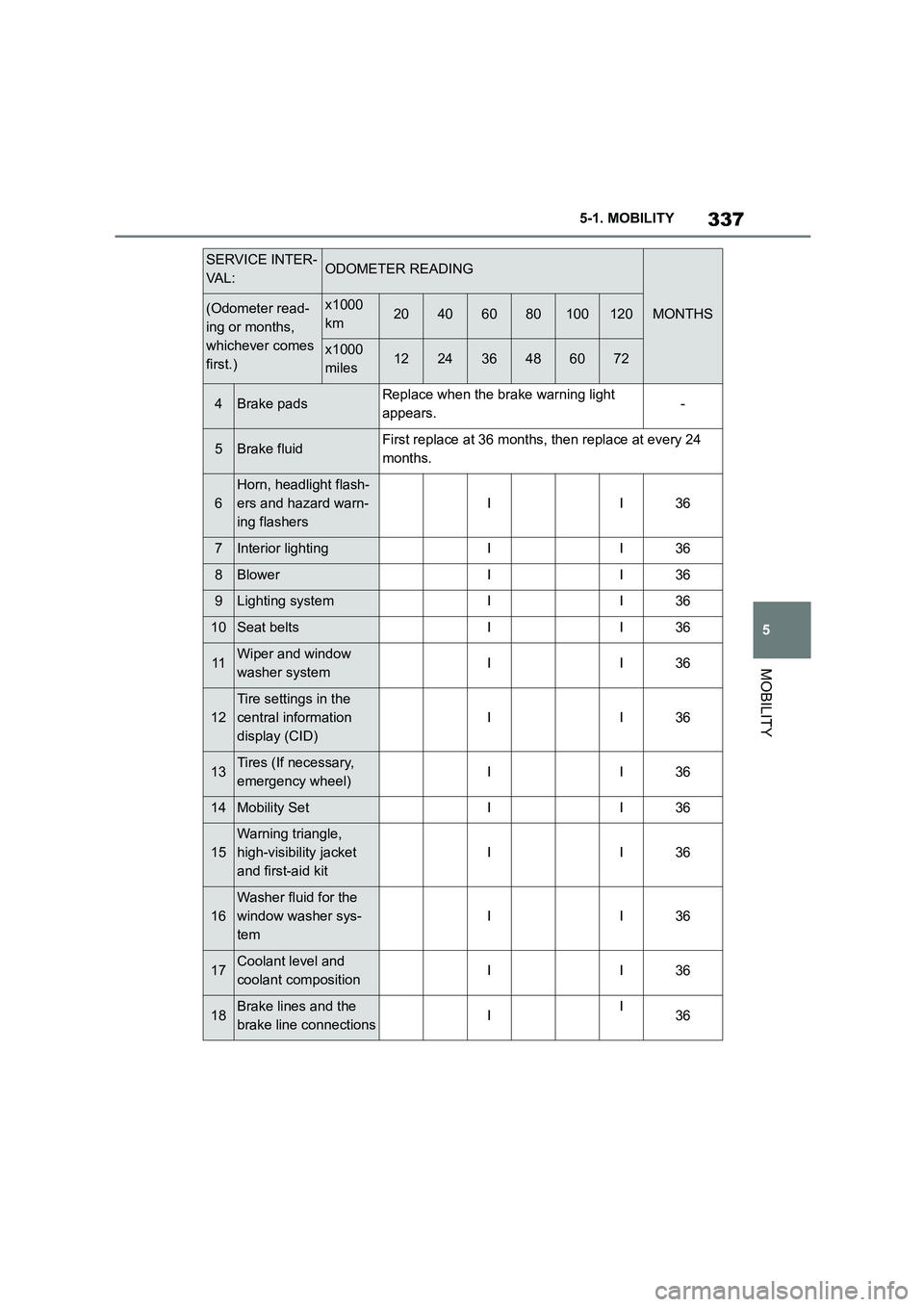
4Brake padsReplace when the brake warning light
appears.-
5Brake fluidFirst replace at 36 months, then replace at every 24
months.
6
Horn, headlight flash-
ers and hazard warn-
ing flashers
II36
7Interior lightingII36
8BlowerII36
9Lighting systemII36
10Seat beltsII36
11Wiper and window
washer systemII36
12
Tire settings in the
central information
display (CID)
II36
13Tires (If necessary,
emergency wheel)II36
14Mobility SetII36
15
Warning triangle,
high-visibility jacket
and first-aid kit
II36
16
Washer fluid for the
window washer sys-
tem
II36
17Coolant level and
coolant compositionII36
18Brake lines and the
brake line connectionsII36
SERVICE INTER-
VA L :ODOMETER READING
MONTHS(Odometer read-
ing or months,
whichever comes
first.)
x1000
km20406080100120
x1000
miles122436486072
Page 350 of 498
3485-1. MOBILITY
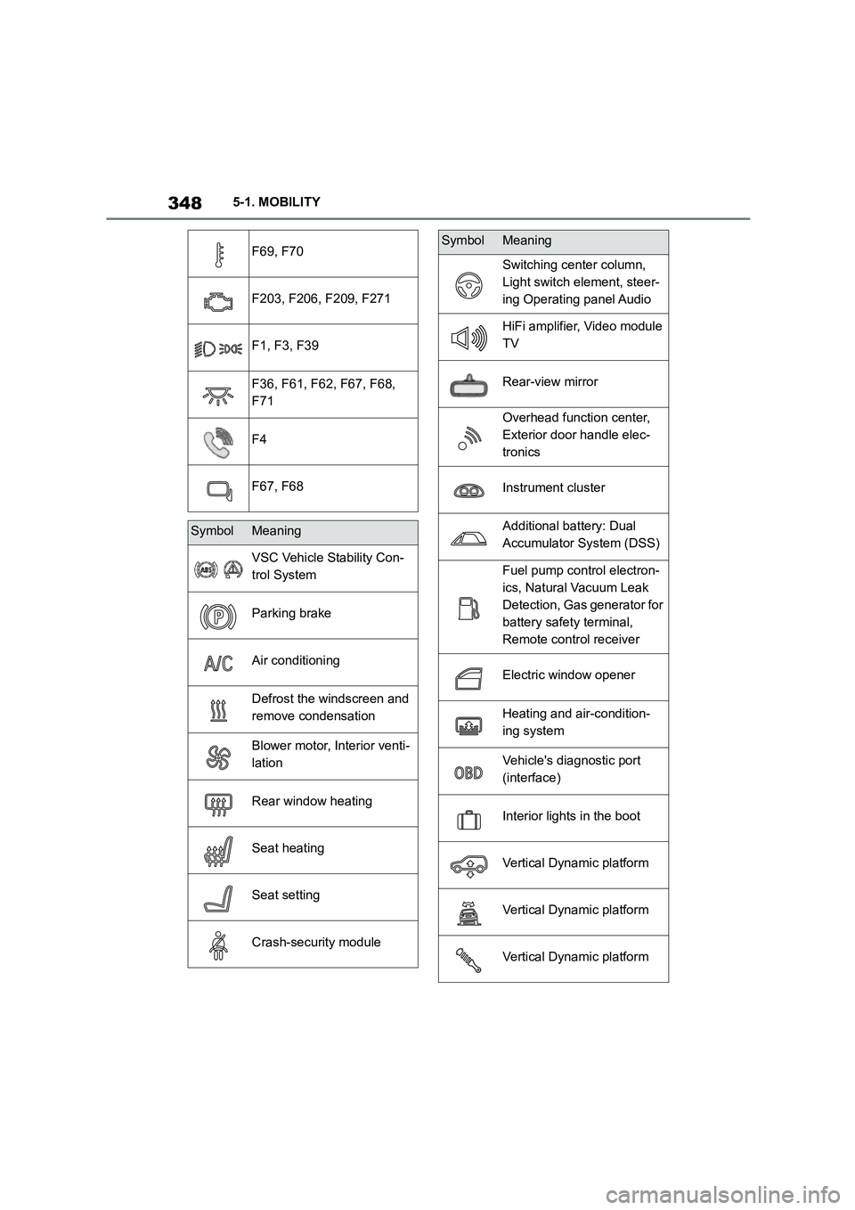
F69, F70
F203, F206, F209, F271
F1, F3, F39
F36, F61, F62, F67, F68,
F71
F4
F67, F68
SymbolMeaning
VSC Vehicle Stability Con-
trol System
Parking brake
Air conditioning
Defrost the windscreen and
remove condensation
Blower motor, Interior venti-
lation
Rear window heating
Seat heating
Seat setting
Crash-security module
Switching center column,
Light switch element, steer-
ing Operating panel Audio
HiFi amplifier, Video module
TV
Rear-view mirror
Overhead function center,
Exterior door handle elec-
tronics
Instrument cluster
Additional battery: Dual
Accumulator System (DSS)
Fuel pump control electron-
ics, Natural Vacuum Leak
Detection, Gas generator for
battery safety terminal,
Remote control receiver
Electric window opener
Heating and air-condition-
ing system
Vehicle's diagnostic port
(interface)
Interior lights in the boot
Vertical Dynamic platform
Vertical Dynamic platform
Vertical Dynamic platform
SymbolMeaning
Page 352 of 498

3505-1. MOBILITY
This chapter describes all standard,
country-specific and special equip-
ment available for the model series.
It may therefore describe equip-
ment and functions which are not
installed in your vehicle, for exam-
ple on account of the special equip-
ment selected or the country
specification. This also applies to
safety-relevant functions and sys-
tems. Please comply with the rele-
vant laws and regulations when
using the corresponding functions
and systems.
Breakdown Assist
Vehicle equipment
If a malfunction occurs
while driving
WA R N I N G
If a malfunction occurs while driving,
immediately stop the vehicle in a safe
place.
If a warning light illuminates or flashes, or a warning message is dis-
played, immediately stop the vehicle
in a safe place. Do not open the hood to inspect the engine, as doing so
may lead to serious injury, such as
steam burns. If a warning message is displayed, perform the necessary pro-
cedures according to the displayed
message or explanation in the owner’s manual.
These warning messages indicate that a malfunction has occurred in a
system or function of the vehicle. If
you continue to drive the vehicle, the engine may stop suddenly, possibly
leading to an accident. Also, even if
no warning lights are illuminated or messages are displayed, if any
abnormal sounds, smells or vibrations
are detected, or of the engine stops suddenly, refrain from opening the
hood to inspect the engine and con-
sult any authorized Toyota retailer or Toyota authorized repairer, or any reli-
able repairer.
WA R N I N G
If you hear a loud noise or feel some-
thing impact the underside of the vehicle while driving, immediately
stop the vehicle in a safe place.
After stopping the vehicle in a safe
place, check the underside of the
vehicle for any leaking brake fluid, oil or fuel. If any fluid is leaking, stop
driving immediately and have the
vehicle inspected by any authorized Toyota retailer or Toyota authorized
repairer, or any reliable repairer.
Page 353 of 498
351
5
5-1. MOBILITY
MOBILITY
WA R N I N G
Brake and fuel lines run under the
floor of the vehicle. If any of these
lines are damaged, the brakes may
fail or leaking fuel may ignite and cause a fire.
WA R N I N G
If the engine stalls while driving, sev-
eral warning lights will illuminate. Depending on vehicle specifications,
the power-assisted brakes and power
steering may stop operating. In this case the braking power will be
reduced and operation of the steering
wheel will become heavy. Although the operation of the brakes and steer-
ing will not be totally lost, they will
require stronger than normal input to
operate. Stop the vehicle in a safe place as soon as possible.
WA R N I N G
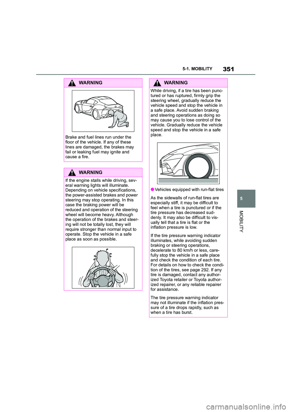
While driving, if a tire has been punc-
tured or has ruptured, firmly grip the
steering wheel, gradually reduce the vehicle speed and stop the vehicle in
a safe place. Avoid sudden braking
and steering operations as doing so may cause you to lo se control of the
vehicle. Gradually reduce the vehicle
speed and stop the vehicle in a safe
place.
●Vehicles equipped with run-flat tires
As the sidewalls of run-flat tires are
especially stiff, it may be difficult to
feel when a tire is punctured or if the tire pressure has decreased sud-
denly. It may also be difficult to vis-
ually tell that a tire is flat or the inflation pressure is low.
If the tire pressure warning indicator illuminates, while avoiding sudden
braking or steering operations,
decelerate to 80 km /h or less, care- fully stop the vehicle in a safe place
and check the condition of each tire.
For details on how to check the condi- tion of the tires, see page 292. If any
tire is damaged, contact any author-
ized Toyota retailer or Toyota author- ized repairer, or any reliable repairer
for assistance.
The tire pressure warning indicator
may not illuminate if the inflation pres-
sure of a tire drops rapidly, such as when a tire has burst.