2022 TOYOTA SUPRA change wheel
[x] Cancel search: change wheelPage 13 of 498

11
1
1-1. NOTES
NOTES
or the driver's behaviour.
These include, for example:
• Status reports relating to the
vehicle and its individual compo-
nents, for example wheel speed,
wheel circumferential velocity,
deceleration, lateral accelera-
tion, fastened seat belts.
• Ambient conditions, for example
temperature, rain sensor signals.
The data is processed within the
vehicle and is usually transient. It is
only saved for longer than the oper-
ating period if it is required in order
to perform services agreed with the
customer.
Electronic parts, for example con-
trol devices and vehicle keys, con-
tain components for storing
technical informat ion. Information
about the vehicle's condition, com-
ponent use and wear, maintenance
requirements, events or errors can
be stored temporarily or perma-
nently.
This information generally docu-
ments the condition of a compo-
nent, a module, a system or the
vehicle surroundings, including:
• Operating states of system com-
ponents, for examp le fill levels,
tyre inflation pr essure, battery
status.
• Malfunctions and faults of impor-
tant system components, for
example lights and brakes.
• Responses of the vehicle to par-
ticular driving situations, for
example triggering of an airbag,
activation of th e drive stability
control systems.
• Information on vehicle-damag-
ing events.
The data is required so that the
control units can perform their func-
tions. It is also used for detecting
and rectifying malfunctions, as well
as to optimise vehicle functions.
Most of this data is transient and is
only processed within the vehicle
itself. Only a small proportion of the
data is stored in event or error
memories in response to specific
circumstances.
Convenience functions, such as
seat, climate or light settings, make
every journey even more pleasant.
The personal settings for these
functions can be saved in a profile
within the vehicle and retrieved on
request, for example if the settings
have been changed by another
driver. Depending on the equip-
ment, these profiles can be saved
in the vehicle manufacturer's
secure data systems. When the
driver changes vehicle, these
saved profiles can simply be
applied to a different vehicle.
The vehicle settings saved in the
vehicle profile can be changed or
deleted at any time.
Electronic components
Personal settings
Page 33 of 498
31
2
2-1. QUICK REFERENCE
QUICK REFERENCE
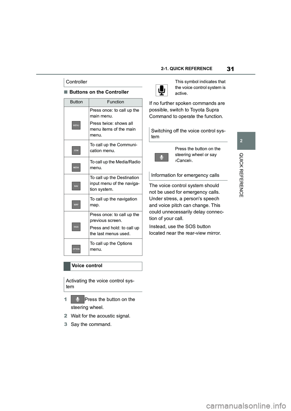
■Buttons on the Controller
1 Press the button on the
steering wheel.
2 Wait for the acoustic signal.
3 Say the command.
If no further spoken commands are
possible, switch to Toyota Supra
Command to operate the function.
The voice control system should
not be used for emergency calls.
Under stress, a person's speech
and voice pitch can change. This
could unnecessarily delay connec-
tion of your call.
Instead, use the SOS button
located near the rear-view mirror.
Controller
ButtonFunction
Press once: to call up the
main menu.
Press twice: shows all
menu items of the main
menu.
To call up the Communi-
cation menu.
To call up the Media/Radio
menu.
To call up the Destination
input menu of the naviga-
tion system.
To call up the navigation
map.
Press once: to call up the
previous screen.
Press and hold: to call up
the last menus used.
To call up the Options
menu.
Voice control
Activating the voice control sys-
tem
This symbol in dicates that
the voice control system is
active.
Switching off the voice control sys-
tem
Press the button on the
steering wheel or say
›Cancel‹.
Information for emergency calls
Page 105 of 498

103
3
3-1. CONTROLS
CONTROLS
is opened.
• Movements inside the vehicle.
• A change in the vehicle's incline,
for instance if an attempt is made
to jack it up and steal the wheels
or to raise it prior to towing away.
• An interruption in the power sup-
ply from the battery.
• Improper use of the socket for
on-board diagnosis OBD.
• The vehicle is locked while a
device is connected to the socket
for on-board diagnosis OBD.
Socket for on-board diagnosis
OBD, see page 332.
The alarm system indicates the fol-
lowing changes visually and audi-
bly:
• Audible alarm: Depending on
local regulations, the acoustic
alarm may be suppressed.
• Visual alarm: By flashing of the
hazard warning lights and, if
applicable, the headlights.
To safeguard the function of the
alarm system, do not modify the
system.
The alarm system is switched off
and on at the same time as the
vehicle is unlocked and locked via
the remote control or Smart Key
System.
The alarm system is triggered on
opening a door if the door has been
unlocked using the integrated key
in the door lock.
To stop the alarm, see page 104.
The boot lid can be opened even
with the alarm system switched on.
On closing the boot lid, it is locked
again and monitored, as long as the
doors are locked. The hazard warn-
ing lights flash once.
• Indicator lamp flashes every 2
seconds: The alarm system is
switched on.
• Indicator lamp flashes for
approximately 10 seconds
before it flashes every 2 sec-
onds: The interior movement
detector and tilt alarm sensor are
not active because doors, bon-
Switching on/off
Opening the doors when the
alarm system is switched on
Opening the boot lid with the
alarm system switched on
Indicator lamp on the
rear-view mirror
Page 109 of 498
107
3
3-1. CONTROLS
CONTROLS
This chapter describes all standard,
country-specific and special equip-
ment available for the model series.
It may therefore describe equip-
ment and functions which are not
installed in your vehicle, for exam-
ple on account of the special equip-
ment selected or the country
specification. This also applies to
safety-relevant functions and sys-
tems. Please comply with the rele-
vant laws and regulations when
using the corresponding functions
and systems.
A seating position that suitably
reflects the requirements of the
occupants is essential for relaxed
driving with minimum fatigue.
In an accident, the correct seating
position plays an important role.
Comply with the notes in the follow-
ing chapters:
• Seats, see page 107.
• Seat belts, see page 111.
• Head restraints, see page 116.
• Airbags, see page 192.
Seats, mirrors and steer-
ing wheel
Vehicle equipment
Safe seating position
Seats
Safety notes
WA R N I N G
Adjusting the seat during a journey
could cause the seat to move unex-
pectedly. You could lose control of the
vehicle. There is a danger of acci- dents. Only adjust the seat on the
driver's side when at a standstill.
WA R N I N G
If the backrest is angled back too far,
the protective effect of the seat belt
will no longer be guaranteed. There is a danger of sliding under the seat belt
in the event of an accident. There is a
danger of injury or even death. Adjust the seat before starting the journey.
Adjust the backre st to the most
upright position possible, and do not change it during the journey.
WA R N I N G
There is a risk of entrapment when
the seats are being moved. There is a danger of injury or damage to prop-
erty. Before making any adjustment,
make sure that the area of movement of the seat is clear.
Page 159 of 498
157
3
3-1. CONTROLS
CONTROLS
3 Depress the brake pedal.
4 Touch the selector lever lock
and engage selector lever posi-
tion N.
5 Switch off drive-ready state.
Standby state then remains switched
on and a vehicle message is shown.
The vehicle can now roll.
Selector lever position P is auto-
matically engaged after approxi-
mately 35 minutes.
If there is a fault, it may not be pos-
sible to change the selector lever
position.
Unlock the transmission lockout
electronically if necessary, see
page 158.
Kick-down enables you to achieve
maximum performance.
Press the accelerator pedal down
beyond the regular full-throttle posi-
tion; resistance will be felt.
The gears can be changed manu-
ally in manual operation.
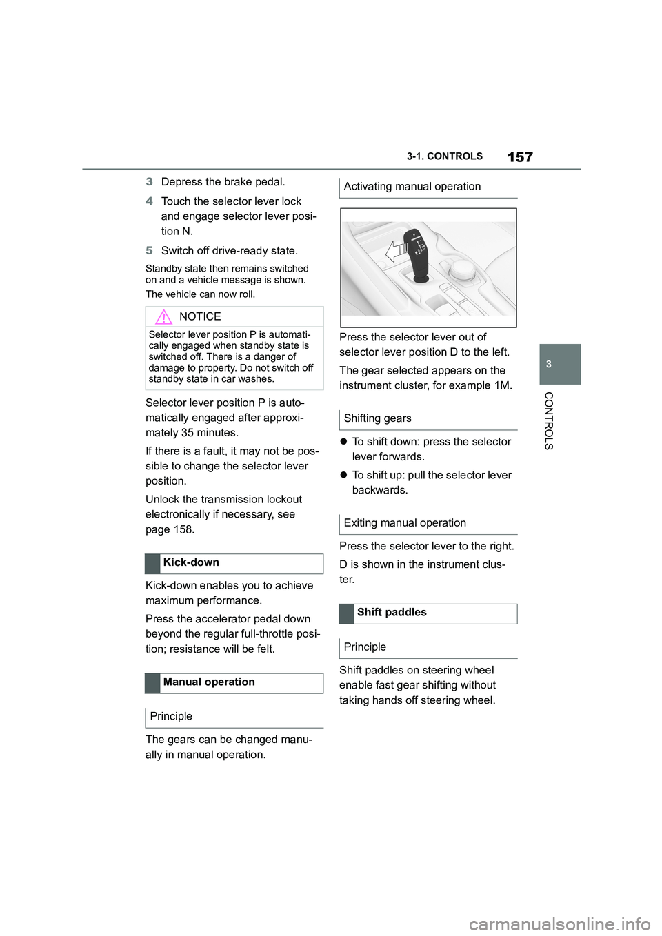
Press the selector lever out of
selector lever position D to the left.
The gear selected appears on the
instrument cluster, for example 1M.
To shift down: press the selector
lever forwards.
To shift up: pull the selector lever
backwards.
Press the selector lever to the right.
D is shown in the instrument clus-
ter.
Shift paddles on steering wheel
enable fast gear shifting without
taking hands off steering wheel.
NOTICE
Selector lever position P is automati- cally engaged when standby state is
switched off. There is a danger of
damage to property. Do not switch off standby state in car washes.
Kick-down
Manual operation
Principle
Activating manual operation
Shifting gears
Exiting manual operation
Shift paddles
Principle
Page 179 of 498
177
3
3-1. CONTROLS
CONTROLS
to the standard.
If signs are detected that apply to
a parallel road.
In the case of country-specific
signs or road layouts.
During the camera calibration
process immediately after vehi-
cle delivery.
The display can be operated when
necessary.
Entertainment source.
Current audio source.
Last calls list.
If applicable, the relevant menu is
opened on the Control Display.
Items displayed may differ depend-
ing on the specifications of the vehi-
cle.
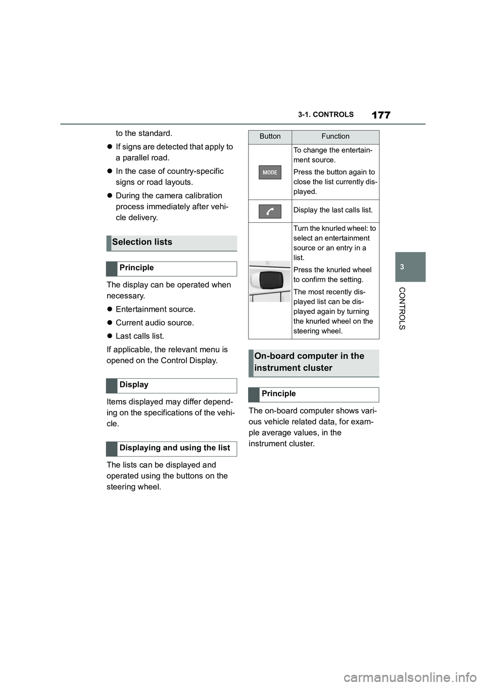
The lists can be displayed and
operated using the buttons on the
steering wheel.
The on-board computer shows vari-
ous vehicle related data, for exam-
ple average values, in the
instrument cluster.
Selection lists
Principle
Display
Displaying and using the list
ButtonFunction
To change the entertain-
ment source.
Press the button again to
close the list currently dis-
played.
Display the last calls list.
Turn the knurled wheel: to
select an entertainment
source or an entry in a
list.
Press the knurled wheel
to confirm the setting.
The most recently dis-
played list can be dis-
played again by turning
the knurled wheel on the
steering wheel.
On-board computer in the
instrument cluster
Principle
Page 235 of 498
233
3
3-1. CONTROLS
CONTROLS
The current speed is adopted as
the speed limit.
When switching on at a standstill or
driving at low speed, 30 km/h/20
mph is set as the speed limit.
When activating the speed limit it is
possible that Vehicle Stability Con-
trol VSC will be switched on and
the drive mode switched to NOR-
MAL.
The system switches off automati-
cally in the followi ng situations, for
example:
When switching the engine off.
When switching on Cruise Con-
trol.
When activating sport mode
using the sport mode switch.
The displays turn off.
The system is interrupted when
reverse gear is engaged or the
transmission is in neutral.
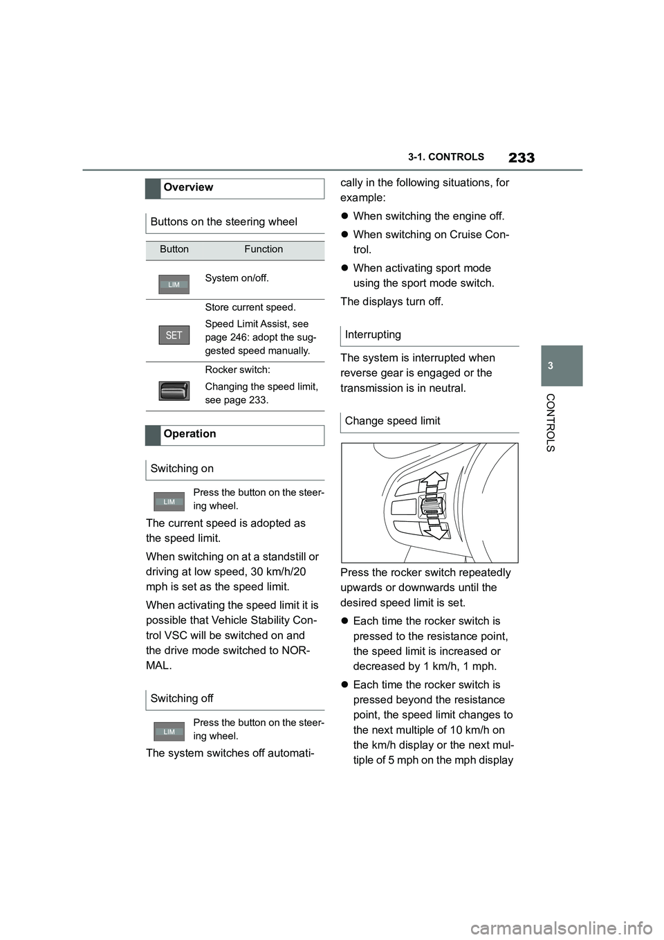
Press the rocker switch repeatedly
upwards or downwards until the
desired speed limit is set.
Each time the rocker switch is
pressed to the resistance point,
the speed limit is increased or
decreased by 1 km/h, 1 mph.
Each time the rocker switch is
pressed beyond the resistance
point, the speed limit changes to
the next multiple of 10 km/h on
the km/h display or the next mul-
tiple of 5 mph on the mph display
Overview
Buttons on the steering wheel
ButtonFunction
System on/off.
Store current speed.
Speed Limit Assist, see
page 246: adopt the sug-
gested speed manually.
Rocker switch:
Changing the speed limit,
see page 233.
Operation
Switching on
Press the button on the steer-
ing wheel.
Switching off
Press the button on the steer-
ing wheel.
Interrupting
Change speed limit
Page 236 of 498
2343-1. CONTROLS
in the speedometer.
If the set speed limit has been
reached or unintentionally
exceeded, for example when driv-
ing downhill, ther e is no active
brake intervention.
If you set a speed limit while driving
which is below the current speed,
the vehicle coasts down to the set
speed limit.
Vehicles with Speed Limit Assist,
see page 246: a change in the
speed limit detected by Speed Limit
Assist can be adopted for the
Speed Limiter as a new speed limit.
The current speed can also be
stored by pressing the button:
The system gives a warning if the
travelling speed exceeds the set
speed limit.
You can intentionally exceed the
speed limit.
To exceed the set speed limit inten-
tionally, fully depress the accelera-
tor pedal.
The limit automatically becomes
active again as soon as the current
speed falls below the set speed
limit.
Depending on the vehicle specifica-
tions, the set speed limit will be dis-
played.
*: if equipped
This system allows a desired speed
to be set using the buttons on the
steering wheel. The desired speed
is then maintained by the system.
Press the button on the steer-
ing wheel.
Exceeding the speed limit
Warning when the speed limit
is exceeded
Visual warning
If the speed limit is exceeded:
the indicator lamp in the
instrument cluster flashes for
as long as you exceed the set
speed limit.
Displays in the instrument
cluster
Indicator lamp
If the indicator lamp is illu-
minated: the system is
switched on.
If the indicator lamp is
flashing: set speed limit is
exceeded.
Grey indicator lamp: the
system is interrupted.
Status display
Cruise Control*
Principle