Page 25 of 268

GETTING TO KNOW YOUR VEHICLE23
STEERING WHEEL
TELESCOPING STEERING COLUMN
This feature allows you to lengthen or shorten the
steering column. The telescoping control handle is
located below the steering wheel at the end of the
steering column.
Telescoping Control Handle
To unlock the steering column, pull the control
handle up. To lengthen or shorten the steering
column, pull the steering wheel outward or push it
inward as desired. To lock the steering column in
position, push the control handle down until fully
engaged.
SEATS
Seats are a part of the Occupant Restraint system
of the vehicle.
MANUAL ADJUSTMENTS
The driver and passenger seats can be adjusted
forward/rearward and reclined. Front and rear height
and lumbar can also be adjusted (if equipped).
Seat Adjustment (Without Swivel Seat)
WARNING!
Do not adjust the steering column while driving.
Adjusting the steering column while driving or
driving with the steering column unlocked, could
cause the driver to lose control of the vehicle.
Failure to follow this warning may result in
serious injury or death.
WARNING!
It is dangerous to ride in a cargo area, inside
or outside of a vehicle. In a collision, people
riding in these areas are more likely to be seri -
ously injured or killed.
Do not allow people to ride in any area of your
vehicle that is not equipped with seats and
seat belts. In a collision, people riding in these
areas are more likely to be seriously injured or
killed.
Be sure everyone in your vehicle is in a seat
and using a seat belt properly.
1 — Forward/Rearward Adjustment Bar
2 — Front Height Adjustment Lever
3 — Rear Height Adjustment Lever
4 — Recliner Knob
5 — Lumbar Knob
2
22_VF_OM_EN_USC_t.book Page 23
Page 26 of 268

24GETTING TO KNOW YOUR VEHICLE
(Continued)
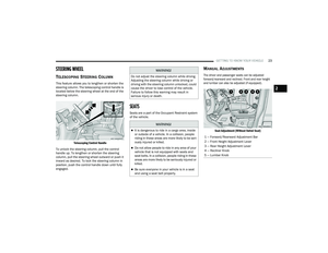
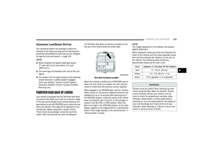
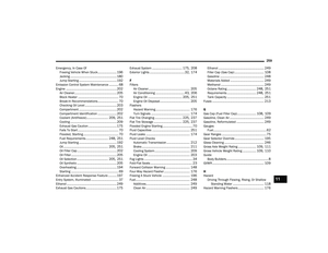
Seat Adjustment (With Swivel Seat)
Forward And Rearward Adjustment
The adjustment bar is at the front of the seat, near
the floor. Pull the bar upward to move the seat
forward or rearward. Release the bar once the
seat is in the desired position. Then, using body
pressure, move forward and rearward on the seat
to be sure that the seat adjusters have latched.
Height Adjustment
Without Swivel Seat
The height adjustment levers are located on the
center outboard side of the seat. Lift up on the
front lever to adjust the front of the seat, or lift up
on the rear lever to adjust the rear of the seat.
To raise the front or rear of the seat, lift the
appropriate lever while none or minimal weight
is applied to the seat.
To lower the front or rear of the seat, lift the
appropriate lever while seated or applying
weight to the seat.
With Swivel Seat
The height adjustment knobs are located on the
center outboard side of the seat. Rotate the front
knob to adjust the front of the seat up or down.
Rotate the rear knob to adjust the rear of the seat
up or down.
Recliner Adjustment
Without Swivel Seat
The recliner knob is on the rear outboard side of the
seat. To recline the seatback, lean back, rotate the
knob rearward to position the seatback as desired.
To return the seatback to its normal upright position,
lean forward, rotate the knob forward until the
seatback is in the upright position.
With Swivel Seat
The recliner lever is located at the lower front
outboard side of the seat. To recline the seatback,
lean forward slightly, pull the lever outward, lean
back to the desired position and release the lever.
To return the seatback to its normal upright
position, lean forward and pull the lever outward.
Release the lever once the seatback is in the
upright position.
1 — Lumbar Knob
2 — Recline Lever
3 — Forward/Rearward Adjustment Bar
4 — Front Height Adjustment Knob
5 — Rear Height Adjustment Knob
WARNING!
Adjusting a seat while driving may be
dangerous. Moving a seat while driving could
result in loss of control which could cause a
collision and serious injury or death.
Seats should be adjusted before fastening the
seat belts and while the vehicle is parked.
Serious injury or death could result from a
poorly adjusted seat belt.
WARNING!
Adjusting a seat while the vehicle is moving is
dangerous. The sudden movement of the seat
could cause you to lose control. The seat belt
might not be adjusted properly and you could
be injured. Adjust the seat only while the
vehicle is parked.
22_VF_OM_EN_USC_t.book Page 24
Page 27 of 268

GETTING TO KNOW YOUR VEHICLE25
Lumbar Support — If Equipped
This feature allows you to increase or decrease the
amount of lumbar support. The lumbar control
knob is located on the rear upper outboard side of
the driver's seatback. Rotate the control forward to
increase and rearward to decrease the desired
amount of lumbar support.
Suspension Seat — If Equipped
The seat is equipped with a mechanical spring
system and hydraulic shock absorber to ensure
maximum comfort and safety. The system of
springs also effectively absorbs impact from
uneven road surfaces. Damper Weight Adjustment
Use the weight adjustment knob, located on the
inboard side of the seat, to set the required setting
based on body weight, with settings between 88 lb
(40 kg) and 286 lb (130 kg).
Weight Adjustment Knob
Swivel Seat — If Equipped
The swivel seat lever is located at the lower front
inboard side of the seat. The seat may be turned
through 180° toward the seat on the opposite side
and approximately 35° toward the door. The seat
may be locked in the driving position or at the
180° position. To swivel the seat, pull the swivel
seat inboard lever outward, turn the seat to the
desired position and release the lever.
Swivel Seat Lever
If the vehicle is equipped with interlocking swivel
seats, the seats must be locked in the facing
forward position while driving. If the seats are not
in the correct position, a warning will appear in the
instrument cluster display.
If the driver or the passenger seats are not locked
in the facing forward position before the first
vehicle movement, shifting out of park is not
allowed until the seats are both locked in the
facing forward position. When the seats are not in
the right position and the first vehicle movement
after ignition START is attempted, a chime and a
message will appear in the instrument cluster
display. Rotate and lock the swivel seats in the
correct position before trying again.
Do not ride with the seatback reclined so that
the shoulder belt is no longer resting against
your chest. In a collision, you could slide under
the seat belt and be seriously or even fatally
injured. Use the recliner only when the vehicle
is parked.
WARNING!
2
22_VF_OM_EN_USC_t.book Page 25
Page 28 of 268

26GETTING TO KNOW YOUR VEHICLE
(Continued)
If the driver or the passenger seats are not locked
in the facing forward position during movement
of the vehicle, a message will appear in the
instrument cluster display and an intermittent
chime will sound until key-off or until the swivel
seats are locked in the facing forward position.
Stop and move the swivel seats in the correct
position before proceeding.
If a fault is present in the system and it is not
possible to check the correct position of the swivel
seats, a message and the generic warning light
appears in the instrument cluster display to inform
about the failure. In these conditions, check the
status of the swivel seats and do not drive the
vehicle until the swivel seats are locked in the
facing forward position.
HEATED SEATS — IF EQUIPPED
On some models, the front driver and
passenger seats may be equipped with
heaters in both the seat cushions and
seatbacks. The controls for the front
heated seats are located on the lower outboard
side of the seat.
Heated Seat Switch
Push the switch once to turn on the heated seats.
Push the switch a second time to shut the heating
elements off.
NOTE:Once a heat setting is selected, heat will be felt
within two to five minutes.
FOLD DOWN TRAY — IF EQUIPPED
If your vehicle is equipped with a bench seat, the
seat is equipped with a fold-down tray that can be
used as a document support surface. To use the
fold-down tray, grab the pull tab and lower the tray.
Lowering The Fold-Down Tray
WARNING!
Persons who are unable to feel pain to the
skin because of advanced age, chronic illness,
diabetes, spinal cord injury, medication,
alcohol use, exhaustion or other physical
condition must exercise care when using the
seat heater. It may cause burns even at low
temperatures, especially if used for long
periods of time.
Do not place anything on the seat or seatback
that insulates against heat, such as a blanket
or cushion. This may cause the seat heater to
overheat. Sitting in a seat that has been over -
heated could cause serious burns due to the
increased surface temperature of the seat.
WARNING!
22_VF_OM_EN_USC_t.book Page 26
Page 29 of 268

GETTING TO KNOW YOUR VEHICLE27
The fold-down tray is equipped with two cup
holders and a support surface with a paper
holder clip.
Closing The Fold-Down Tray
ADJUSTABLE ARMRESTS — IF EQUIPPED
The seat adjustable armrest can be raised and
adjusted for height. Underneath the front of the
armrest is the adjuster wheel which will adjust the
height of the armrest up or down.
Adjuster Wheel Location
Turn the adjuster wheel to the right or left to adjust
the height of the armrest up or down.
Adjuster Wheel
HEAD RESTRAINTS
Head restraints are designed to reduce the risk of
injury by restricting head movement in the event of
a rear impact. Head restraints should be adjusted
so that the top of the head restraint is located
above the top of your ear.
WARNING!
All occupants, including the driver, should not
operate a vehicle or sit in a vehicle’s seat until
the head restraints are placed in their proper
positions in order to minimize the risk of neck
injury in the event of a crash.
Head restraints should never be adjusted
while the vehicle is in motion. Driving a vehicle
with the head restraints improperly adjusted
or removed could cause serious injury or
death in the event of a collision.
2
22_VF_OM_EN_USC_t.book Page 27
Page 30 of 268

28GETTING TO KNOW YOUR VEHICLE
Front Head Restraint Adjustment
To raise the head restraint, pull upward on the
head restraint. To lower the head restraint, push
the adjustment button located on the base of the
head restraint and push downward on the head
restraint.
Adjustment Buttons
NOTE:Do not reposition the head restraint 180 degrees
to the incorrect position in an attempt to gain addi -
tional clearance to the back of the head.
Front Head Restraint Removal
To remove the head restraint, raise it up as far as
it can go. Then, push the adjustment button and
the release button at the base of each post while
pulling the head restraint up. To reinstall the head
restraint, push the adjustment button and the
release button at the base of each post and put the
head restraint posts into the holes. Then, adjust it
to the appropriate height.
NOTE:Do not reposition the head restraint 180 degrees
to the incorrect position in an attempt to gain addi -
tional clearance to the back of the head.
UCONNECT VOICE RECOGNITION —
IF EQUIPPED
INTRODUCING VOICE RECOGNITION
Start using Uconnect Voice Recognition with these
helpful quick tips. It provides the key Voice
Commands and tips you need to know to control
your vehicle’s Voice Recognition (VR) system.
NOTE:Voice Recognition is only available on the
Uconnect 5 NAV With 10.1-inch Display.
BASIC VOICE COMMANDS
The following can be given at any point while using
your Uconnect system.
Push the VR button and after the beep, say a
command. You can also say the system “Wake Up”
word, “Hey Uconnect” or “Hey Ram”, and then say
a command. The factory default Wake Up word is
set to “Hey Uconnect” and can be reprogrammed
through the Uconnect Settings. After the beep, say:
“ Cancel ” to stop a current voice session.
“Help ” to hear a list of suggested Voice
Commands.
“ Repeat ” to listen to the system prompts again.
Notice the visual cues that inform you of your Voice
Recognition system’s status.
1 — Release Button
2 — Adjustment Button
WARNING!
A loose head restraint thrown forward in a collision
or hard stop could cause serious injury or death to
occupants of the vehicle. Always securely stow
removed head restraints in a location outside the
occupant compartment.
ALL the head restraints MUST be reinstalled in
the vehicle to properly protect the occupants.
Follow the preceding reinstallation instruc
-
tions prior to operating the vehicle or occu -
pying a seat.
22_VF_OM_EN_USC_t.book Page 28
Page 31 of 268

GETTING TO KNOW YOUR VEHICLE29
GET STARTED
The VR button is used to activate/deactivate
your Voice Recognition system. You can also use
the system’s “Wake Up” word to activate voice
recognition. The “Wake Up” word can be set
through the Uconnect Settings Úpage 120.
Helpful hints for using Voice Recognition:
Reduce background noise. Wind noise and
passenger conversations are examples of noise
that may impact recognition.
Speak clearly at a normal pace and volume
while facing straight ahead.
Each time you give a Voice Command, first push the
VR button, wait until after the beep, then say your
Voice Command. Also, you can say the vehicle
“Wake Up” word to issue a Voice Command.
The available “Wake Up” words are “Hey Uconnect”
and “Hey Ram”.
You can interrupt the help message or system
prompts by pushing the VR button and saying a
Voice Command from the current category.
Uconnect Voice Command Buttons
ADDITIONAL INFORMATION
© 2021 FCA US LLC. All rights reserved. Mopar and
Uconnect are registered trademarks and Mopar
Owner Connect is a trademark of FCA US LLC.
SiriusXM® and all related marks and logos are
trademarks of SiriusXM® Radio Inc. Ú
page 256.For Uconnect system support, call
1-877-855-8400 (24 hours a day 7 days a week)
or visit
DriveUconnect.com (US) or DriveUconnect.ca (Canada).
MIRRORS
INSIDE REARVIEW MIRROR
Manual Mirror — If Equipped
The rearview mirror can be adjusted up, down, left,
and right. The mirror should be adjusted to center
on the view through the rear window.
Headlight glare can be reduced by moving the
small control under the mirror to the night position
(toward the rear of the vehicle). The mirror should
be adjusted while set in the day position (toward
the windshield).
Adjusting Rearview Mirror
1 — Push To Answer a Phone Call
2 — For Vehicles Equipped With Navigation: Push
The Voice Recognition Button To Begin Radio,
Media, Navigation, Climate, Start Or Answer A
Phone Call, And Send Or Receive A Text
2 — For Vehicles Not Equipped With Navigation:
Push The Phone Button To Answer An Incoming
Phone Call
3 — Push To End A Phone Call
2
22_VF_OM_EN_USC_t.book Page 29
Page 32 of 268

30GETTING TO KNOW YOUR VEHICLE
Digital Rearview Mirror — If Equipped
The Digital Rearview Mirror provides a high
definition, wide and unobstructed view of the road
behind while driving.
Position the mirror in the regular Automatic
Dimming Mirror mode, then activate the Digital
Rearview Mirror mode.
To activate the Digital Rearview Mirror, pull the
on/off control lever on the bottom of the mirror
rearward toward the driver.
Digital Rearview Mirror
Push the menu button next to the on/off control to
access the following mirror options:Brightness
Tilt
Pan (if equipped)
Use the left and right buttons to scroll through
menu options.
When not in use, push the on/off forward toward
the windshield to return the mirror to the regular
Automatic Dimming Mirror.
NOTE:The Digital Rearview Mirror is not as effective when
driving in the following conditions:
Nighttime in low light applications
Bad weather conditions (e.g. extreme haze,
snow/slush)
If it becomes difficult to see clearly in the display,
the camera may need to be cleaned. If snow, ice,
mud, or any foreign substance builds up on the
camera lens, clean the lens, rinse with water, and
dry with a soft cloth. Do not cover the lens.
Camera Location
OUTSIDE MIRRORS
To receive maximum benefit, adjust the outside
mirror(s) to center on the adjacent lane of traffic
with a slight overlap of the view obtained on the
inside mirror.
1 — On/Off Control
2 — Menu Button
3 — Left Scroll Button
4 — Right Scroll Button
WARNING!
Vehicles and other objects seen in an outside
convex mirror will look smaller and farther away
than they really are. Relying too much on side
convex mirrors could cause you to collide with
another vehicle or other object. Use your inside
mirror when judging the size or distance of a
vehicle seen in a side convex mirror.
22_VF_OM_EN_USC_t.book Page 30