Page 105 of 268

STARTING AND OPERATING103
When only a single lane marking is detected, a
haptic or a torque warning will not be provided.
NOTE:When operating conditions have been met, the
LaneSense system will monitor if the driver’s
hands are on the steering wheel and provide an
audible and visual warning to the driver if removed.
The system will cancel if the driver does not return
their hands to the wheel.
TURNING LANESENSE ON OR OFF
The LaneSense button is located on the
switch panel below the Uconnect display.
To turn the LaneSense system on, push the
LaneSense button (LED turns off). A “LaneSense
On” message is shown in the instrument cluster
display.
To turn the LaneSense system off, push the
LaneSense button twice (LED turns on).
NOTE:The LaneSense system will retain the last system
state on or off from the last ignition cycle when the
ignition is placed in the ON/RUN position.
LANESENSE WARNING MESSAGE
The LaneSense system will indicate the current
lane drift condition through the instrument cluster
display.
When the LaneSense system is on, the lane lines
are gray when both of the lane boundaries have
not been detected and the LaneSense telltale
is solid white.
System ON (Gray Lines) With White Telltale
Left Lane Departure — Only Left Lane Detected
When the LaneSense system is on, the Lane -
Sense Telltale is solid white when only the
left lane marking has been detected and the
system is ready to provide visual warnings in the
instrument cluster display if an unintentional
lane departure occurs on the left side.
When the LaneSense system senses the lane
has been approached and is in a lane departure
situation, the visual warning in the instrument
cluster display will show the left lane line
flashing yellow (on/off). The LaneSense telltale changes from solid white to flashing yellow.
Lane Approached (Flashing Yellow Lane Line) With Yellow Telltale
NOTE:The LaneSense system operates with similar
behavior for a right lane departure when only the
right lane marking has been detected.
4
22_VF_OM_EN_USC_t.book Page 103
Page 106 of 268

104STARTING AND OPERATING
Left Lane Departure — Both Lane Lines Detected
When the LaneSense system is on and both the
lane markings have been detected, the system is
"armed" to provide visual warnings in the instru-
ment cluster display and a torque warning in the
steering wheel if an unintentional lane departure
occurs. The lane lines turn from gray to white and
the LaneSense telltale is solid green.
Lanes Sensed (White Lines) With Green Telltale
When the LaneSense system senses a lane drift
situation, the left lane line turns solid yellow.
The LaneSense telltale changes from solid
green to solid yellow. At this time torque is
applied to the steering wheel in the opposite
direction of the lane boundary. For example: If approaching the left side of the
lane the steering wheel will turn to the right.
Lane Sensed (Solid Yellow Lane Line) With Solid Yellow Telltale
When the LaneSense system senses the lane has
been approached and is in a lane departure situ -
ation, the left lane line flashes yellow (on/off). The
LaneSense telltale changes from solid yellow
to flashing yellow. At this time torque is applied to
the steering wheel in the opposite direction of the
lane boundary.
For example: If approaching the left side of the
lane the steering wheel will turn to the right.
Lane Approached (Flashing Yellow Lane Line) With Flashing Yellow Telltale
NOTE:The LaneSense system operates with similar
behavior for a right lane departure.
22_VF_OM_EN_USC_t.book Page 104
Page 107 of 268
 that you ca")
STARTING AND OPERATING105
CHANGING LANESENSE STATUS
The LaneSense system has settings to adjust the
intensity of the torque warning and the warning zone
sensitivity (Early/Medium/Late) that you can configure
through the Uconnect system
Ú
page 120.
NOTE:
When enabled the system operates above
37 mph (60 km/h) and below 112 mph
(180 km/h).
The warnings are disabled with use of the turn
signal.
The system will not apply torque to the steering
wheel whenever a safety system engages
(Anti-Lock Brakes, Traction Control System,
Electronic Stability Control, Forward Collision
Warning, etc.).
PARKVIEW REAR BACK UP CAMERA
Your vehicle is equipped with the ParkView Rear Back
Up Camera that allows you to see an on-screen image
of the rear surroundings of your vehicle whenever the
gear selector is put into REVERSE and/or when the rear
doors are opened. The image will be displayed on the
touchscreen display along with a caution note to
“Check Entire Surroundings” across the top of the
screen. After five seconds this note will disappear. The ParkView Rear Back Up Camera is located on the
top rear of the vehicle below the center light.
Rear Back Up Camera Location
When the vehicle is shifted out of REVERSE and/or
when the rear doors are closed, the rear camera
mode is exited and the previous screen appears.
When engaged in the REVERSE gear, with the “Camera
Delay” turned on, the camera image will continue to be
displayed for up to 10 seconds after switching out of
the REVERSE position, unless the speed of the vehicle
does not exceed 8 mph (13 km/h), or that the gear is
placed in the NEUTRAL or PARK position. When the
gear is no longer in the REVERSE position, on the radio
display, together to the images behind it, a deactivation
button of the image displays on the camera screen, if
“Camera Delay” is active.
NOTE:The image displayed on the display may appear
slightly deformed.
When displayed, static grid lines will illustrate the
width of the vehicle and will show separate zones
that will help indicate the distance to the rear of
the vehicle. The following table shows the
approximate distances for each zone:
Zone Distance To The Rear Of The Vehicle Red 0 - 1 ft (0 - 30 cm)
Yellow 1 ft - 3 ft (30 cm - 1 m) Green 3 ft or greater (1 m or greater)
WARNING!
Drivers must be careful when backing up even
when using the Rear Back Up Camera. Always
check carefully behind your vehicle, and be
sure to check for pedestrians, animals, other
vehicles, obstructions, or blind spots before
backing up. You are responsible for the safety of
your surroundings and must continue to pay
attention while backing up. Failure to do so can
result in serious injury or death.
4
22_VF_OM_EN_USC_t.book Page 105
Page 108 of 268

106STARTING AND OPERATING
NOTE:
If snow, ice, mud, or any foreign substance builds up
on the camera lens, clean the lens, rinse with water,
and dry with a soft cloth. Do not cover the lens.
SURROUND VIEW CAMERA SYSTEM —
IF EQUIPPED
Your vehicle may be equipped with the Surround View
Camera system that allows you to see an on-screen
image of the surroundings and Top View of your vehicle
whenever the gear selector is put into REVERSE or a
different view is selected through the touchscreen soft
buttons. The Top View of the vehicle will show which
doors are open. The image will be displayed on the
touchscreen display along with a caution note “Check
Entire Surroundings” across the top of the screen. After five seconds, this note will disappear. The
Surround View Camera system is comprised of four
sequential cameras located in the front grille, rear
CHMSL (top rear of the vehicle below the center light)
and side mirrors.
NOTE:The Surround View Camera system has program
-
mable settings that may be selected through the
Uconnect system Ú page 120.
When the vehicle is shifted into REVERSE, the Rear
View and Top View is the default view of the system.
When the vehicle is shifted out of REVERSE (with
camera delay turned on), the camera image will
continue to be displayed for up to 10 seconds unless
the vehicle speed exceeds 8 mph (13 km/h), the
vehicle is shifted into PARK, or the ignition is placed in
the OFF position. There is a touchscreen button “X” to
disable the display of the camera image.
When the vehicle is shifted out of REVERSE (with
camera delay turned off), the Surround View system is
exited and the last known screen appears again.
Whenever the Rear View Camera image is activated
through the Back Up Camera button in the Controls
menu, and the vehicle speed is greater than, or equal
to, 8 mph (13 km/h), a display timer for the image is
initiated. The image will continue to be displayed until
the display timer exceeds 10 seconds.
NOTE:
If the vehicle speed remains below 8 mph
(13 km/h), the Rear View Camera image will be
displayed continuously until deactivated via the
touchscreen button "X", the transmission is
shifted into PARK, or the ignition is placed in the
OFF position.
The touchscreen button "X" to disable display of
the camera image is made available ONLY when
the vehicle is not in REVERSE.
When enabled, active guidelines are overlaid on
the image to illustrate the width of the vehicle,
including the side view mirrors and its projected
back up path based on the steering wheel position.
Different colored zones indicate the distance to
the rear of the vehicle.
The following table shows the approximate
distances for each zone:
CAUTION!
To avoid vehicle damage, ParkView should
only be used as a parking aid. The ParkView
camera is unable to view every obstacle or
object in your drive path.
To avoid vehicle damage, the vehicle must be
driven slowly when using ParkView to be able
to stop in time when an obstacle is seen. It is
recommended that the driver look frequently
over his/her shoulder when using ParkView.
Zone Distance To The Rear Of The Vehicle
Red 0 - 1 ft (0 - 30 cm)
Yellow 1 ft - 6.5 ft (30 cm - 2 m) Green 6.5 ft or greater (2 m or greater)
22_VF_OM_EN_USC_t.book Page 106
Page 109 of 268

STARTING AND OPERATING107
Modes Of Operation
“Manual” activation of the Surround View system
is selected by pressing the Surround View Camera
soft key located in the Controls screen within the
Uconnect system.
Top View
The Top View will show in the Uconnect system with
Rear View or Front View in a split screen display.
There are integrated ParkSense arcs in the image
at the front and rear of the vehicle. The arcs will
change color from yellow to red corresponding the
distance zones to the oncoming object.
Surround View Camera View
NOTE:
Front tires will be in image when the tires are
turned.
Due to wide angle cameras in the mirrors, the
image will appear distorted.
Top View will show which sliding doors are open.
Open front doors will remove outside image.
Rear View This is the default view of the system in
REVERSE and is always paired with the
Top View of the vehicle with optional
active guidelines for the projected path
when enabled.
Rear Cross Path View
Pressing the Rear Cross Path soft key will
give the driver a wider angle view of the
Rear View. The Top View will be disabled
when this is selected.
Front View
The Front View will show you what is
immediately in front of the vehicle and is
always paired with the Top View of the
vehicle.
Front Cross Path View Pressing the Front Cross Path soft key
will give the driver a wider angle view of
the Front View. The Top View will be
disabled when this is selected.
Back Up Camera View Pressing the Back Up Camera soft key
will provide a full screen rear view.
NOTE:If the Back Up Camera was selected through the
Surround View Camera menu, exiting out of screen
display will return to the Surround View menu.
If the Back Up Camera was manually activated
through the Controls menu of the Uconnect
system, exiting out of the display screen will return
to the Controls menu.
Deactivation
The system can be deactivated under the following
conditions:
The speed of the vehicle is greater than
8 mph (13 km/h).
The vehicle shifted into PARK.
The vehicle is in any gear other than REVERSE
and the “X” button is pressed.
The camera delay system is turned off manually
through the Uconnect Settings Ú page 120.
NOTE:
If snow, ice, mud, or any foreign substance
builds up on the camera lenses, clean the
lenses, rinse with water, and dry with a soft
cloth. Do not cover the lenses.
If a malfunction with the system has occurred,
see an authorized dealer.
4
22_VF_OM_EN_USC_t.book Page 107
Page 110 of 268

REFUELING THE VEHICLE
The gas cap is located behind the fuel filler door on
the left side of the vehicle. If the gas cap is lost or
damaged, be sure to use")
108STARTING AND OPERATING
(Continued)
REFUELING THE VEHICLE
The gas cap is located behind the fuel filler door on
the left side of the vehicle. If the gas cap is lost or
damaged, be sure to use the correct replacement
cap for this vehicle.
1. Open the fuel filler door.
2. Remove the fuel cap by rotating it counter-
clockwise.
Fuel Filler
3. Fully insert the fuel nozzle into the filler pipe.
4. Fill the vehicle with fuel.
NOTE:
When the fuel nozzle “clicks” or shuts off,
the fuel tank is full.
Wait five seconds before removing the fuel
nozzle to allow excess fuel to drain from the
nozzle. 5. Remove the fuel nozzle, reinstall fuel cap and
close fuel filler door.
NOTE:During fuel fill, nozzle position could affect the flow
of fuel. For best results, allow the nozzle to rest
naturally in the filler tube - do not raise the handle
to increase the fill angle.
WARNING!
Drivers must be careful when backing up even
when using the Surround View Camera. Always
check carefully behind your vehicle, and be sure
to check for pedestrians, animals, other
vehicles, obstructions, or blind spots before
backing up. You are responsible for the safety of
your surroundings and must continue to pay
attention while backing up. Failure to do so can
result in serious injury or death.
CAUTION!
To avoid vehicle damage, Surround View
should only be used as a parking aid.
The Surround View camera is unable to view
every obstacle or object in your drive path.
To avoid vehicle damage, the vehicle must be
driven slowly when using Surround View to be
able to stop in time when an obstacle is seen.
It is recommended that the driver look
frequently over his/her shoulder when using
Surround View.
WARNING!
Never have any smoking materials lit in or
near the vehicle when the fuel door is open or
the tank is being filled.
Never add fuel when the engine is running.
This is in violation of most state and federal
fire regulations and may cause the Malfunc -
tion Indicator Light to turn on.
A fire may result if fuel is pumped into a
portable container that is inside of a vehicle.
You could be burned. Always place fuel
containers on the ground while filling.
CAUTION!
Damage to the fuel system or emissions
control system could result from using an
improper fuel tank filler tube cap.
A poorly fitting fuel filler cap could let impuri -
ties into the fuel system.
22_VF_OM_EN_USC_t.book Page 108
Page 111 of 268

STARTING AND OPERATING109
NOTE:
Tighten the fuel filler cap until you hear a
“clicking” sound. This is an indication that the
fuel filler cap is properly tightened.
If the gas cap is not tightened properly, the MIL
may come on. Be sure the gas cap is tightened
every time the vehicle is refueled.
LOOSE FUEL FILLER CAP MESSAGE
If the vehicle diagnostic system determines that the
fuel filler cap is loose, improperly installed, or
damaged, a “Check Fuel Cap” message will be
displayed in the instrument cluster display
Ú
page 55.
Tighten the fuel filler cap until a “clicking” sound is
heard. This is an indication that the fuel filler cap is
properly tightened.
If the problem continues, the message will appear
the next time the vehicle is started. See an
authorized dealer as soon as possible.
VEHICLE LOADING
As required by National Highway Traffic Safety
Administration regulations, your vehicle has a
certification label affixed to the driver's side door or
B-pillar.
If seats are removed for carrying cargo, do not
exceed the specified GVWR and GAWR.
VEHICLE CERTIFICATION LABEL
Your vehicle has a Vehicle Certification Label
affixed to the driver’s side B-pillar or the rear of the
driver’s door.
The label contains the following information:
Name of manufacturer
Month and year of manufacture
Gross Vehicle Weight Rating (GVWR)
Gross Axle Weight Rating (GAWR) front and rear
Vehicle Identification Number (VIN)
Type of vehicle
Month, Day, and Hour (MDH) of manufacture
The bar code allows a computer scanner to read
the VIN.
GROSS VEHICLE WEIGHT RATING
(GVWR)
The GVWR is the total allowable weight of your
vehicle. This includes driver, passengers, and
cargo. The total load must be limited so that you do
not exceed the GVWR.
GROSS AXLE WEIGHT RATING (GAWR)
The GAWR is the maximum capacity of the front
and rear axles. Distribute the load over the front
and rear axles evenly. Make sure that you do not
exceed either front or rear GAWR.
TIRE SIZE
The tire size on the Vehicle Certification Label
represents the actual tire size on your vehicle.
Replacement tires must be equal to the load
capacity of this tire size.
A poorly fitting fuel filler cap may cause the
Malfunction Indicator Light (MIL) to turn on.
To avoid fuel spillage and overfilling, do not
“top off” the fuel tank after filling. When the
fuel nozzle “clicks” or shuts off, the fuel tank
is full.
CAUTION!
WARNING!
Because the front wheels steer the vehicle, it is
important that you do not exceed the maximum front
or rear GAWR. A dangerous driving condition can
result if either rating is exceeded. You could lose
control of the vehicle and have a collision.
4
22_VF_OM_EN_USC_t.book Page 109
Page 112 of 268

110STARTING AND OPERATING
RIM SIZE
This is the rim size that is appropriate for the tire
size listed.
INFLATION PRESSURE
This is the cold tire inflation pressure for your
vehicle for all loading conditions up to full Gross
Axle Weight Rating (GAWR).
CURB WEIGHT
The curb weight of a vehicle is defined as the total
weight of the vehicle with all fluids, including
vehicle fuel, at full capacity conditions, and with
no occupants or cargo loaded into the vehicle. The
front and rear curb weight values are determined
by weighing your vehicle on a commercial scale
before any occupants or cargo are added.
OVERLOADING
The load carrying components (axle, springs,
tires, wheels, etc.) of your vehicle will provide
satisfactory service as long as you do not exceed
the Gross Vehicle Weight Rating (GVWR) and the
front and rear Gross Axle Weight Rating (GAWR).
The best way to figure out the total weight of your
vehicle is to weigh it when it is fully loaded and
ready for operation. Weigh it on a commercial scale
to ensure that it is not over the GVWR. Figure out the weight on the front and rear axle of
the vehicle separately. It is important that you
distribute the load evenly over the front and rear
axles.
Overloading can cause potential safety hazards
and shorten useful service life. Heavier axles or
suspension components do not necessarily
increase the vehicle's GVWR.
LOADING
To load your vehicle properly, first figure out its
empty weight, axle-by-axle and side-by-side. Store
heavier items down low and be sure you distribute
their weight as evenly as possible. Stow all loose
items securely before driving. If weighing the
loaded vehicle shows that you have exceeded
either Gross Axle Weight Rating (GAWR), but the
total load is within the specified Gross Vehicle
Weight Rating (GVWR), you must redistribute the
weight. Improper weight distribution can have an
adverse effect on the way your vehicle steers and
handles and the way the brakes operate.
NOTE:Refer to the Vehicle Certification Label affixed to
the rear of the driver's door for your vehicle's GVWR
and GAWRs.
TRAILER TOWING
In this section you will find safety tips and
information on limits to the type of towing you can
reasonably do with your vehicle. Before towing a
trailer, carefully review this information to tow your
load as efficiently and safely as possible.
To maintain the New Vehicle Limited Warranty
coverage, follow the requirements and
recommendations in this manual concerning
vehicles used for trailer towing.
COMMON TOWING DEFINITIONS
The following trailer towing related definitions
will assist you in understanding the following
information:
Gross Vehicle Weight Rating (GVWR)
The GVWR is the total allowable weight of your
vehicle. This includes driver, passengers, cargo
and tongue weight. The total load must be limited
so that you do not exceed the GVWR Ú
page 109.
Gross Combination Weight Rating (GCWR)
The GCWR is the total allowable weight of your
vehicle and trailer when weighed in combination.
22_VF_OM_EN_USC_t.book Page 110
 1
1 2
2 3
3 4
4 5
5 6
6 7
7 8
8 9
9 10
10 11
11 12
12 13
13 14
14 15
15 16
16 17
17 18
18 19
19 20
20 21
21 22
22 23
23 24
24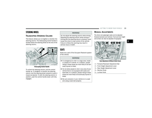 25
25 26
26 27
27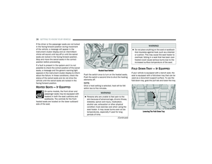 28
28 29
29 30
30 31
31 32
32 33
33 34
34 35
35 36
36 37
37 38
38 39
39 40
40 41
41 42
42 43
43 44
44 45
45 46
46 47
47 48
48 49
49 50
50 51
51 52
52 53
53 54
54 55
55 56
56 57
57 58
58 59
59 60
60 61
61 62
62 63
63 64
64 65
65 66
66 67
67 68
68 69
69 70
70 71
71 72
72 73
73 74
74 75
75 76
76 77
77 78
78 79
79 80
80 81
81 82
82 83
83 84
84 85
85 86
86 87
87 88
88 89
89 90
90 91
91 92
92 93
93 94
94 95
95 96
96 97
97 98
98 99
99 100
100 101
101 102
102 103
103 104
104 105
105 106
106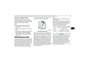 107
107 108
108 109
109 110
110 111
111 112
112 113
113 114
114 115
115 116
116 117
117 118
118 119
119 120
120 121
121 122
122 123
123 124
124 125
125 126
126 127
127 128
128 129
129 130
130 131
131 132
132 133
133 134
134 135
135 136
136 137
137 138
138 139
139 140
140 141
141 142
142 143
143 144
144 145
145 146
146 147
147 148
148 149
149 150
150 151
151 152
152 153
153 154
154 155
155 156
156 157
157 158
158 159
159 160
160 161
161 162
162 163
163 164
164 165
165 166
166 167
167 168
168 169
169 170
170 171
171 172
172 173
173 174
174 175
175 176
176 177
177 178
178 179
179 180
180 181
181 182
182 183
183 184
184 185
185 186
186 187
187 188
188 189
189 190
190 191
191 192
192 193
193 194
194 195
195 196
196 197
197 198
198 199
199 200
200 201
201 202
202 203
203 204
204 205
205 206
206 207
207 208
208 209
209 210
210 211
211 212
212 213
213 214
214 215
215 216
216 217
217 218
218 219
219 220
220 221
221 222
222 223
223 224
224 225
225 226
226 227
227 228
228 229
229 230
230 231
231 232
232 233
233 234
234 235
235 236
236 237
237 238
238 239
239 240
240 241
241 242
242 243
243 244
244 245
245 246
246 247
247 248
248 249
249 250
250 251
251 252
252 253
253 254
254 255
255 256
256 257
257 258
258 259
259 260
260 261
261 262
262 263
263 264
264 265
265 266
266 267
267