Page 49 of 268

GETTING TO KNOW YOUR VEHICLE47
The power inverter is designed with built-in
overload protection. If the power rating of
150 Watts is exceeded, the power inverter will
automatically shut down. Once the electrical
device has been removed from the outlet the
inverter should automatically reset. To avoid
overloading the circuit, check the power ratings on
electrical devices prior to using the inverter.
AUXILIARY SWITCHES — IF EQUIPPED
Your vehicle may be equipped with two auxiliary
switches located on the instrument panel to the
left of the steering column which can be used to
power various electronic devices. Connections to
the switches are found in the right central pillar
fuse panel at the base of the passenger side
B-pillar.
Auxiliary Switches
Auxiliary Switch 1 is configured to constant battery
feed, while Auxiliary Switch 2 is configured to
ignition feed.
For further information on using the auxiliary
switches, please refer to the Ram Body Builder’s
Guide by accessing
www.rambodybuilder.com
and choosing the appropriate links.
WIRELESS CHARGING PAD —
I
F EQUIPPED
Wireless Charging Pad
Your vehicle may be equipped with a 15W 3A Qi
wireless charging pad located below the center
stack. This charging pad is designed to wirelessly
charge your Qi enabled mobile phone. Qi is a
standard that allows wireless charging of your
mobile phone.
Your mobile phone must be designed for Qi wireless
charging. If the phone is not equipped with Qi wireless
charging functionality, an aftermarket sleeve or a
specialized back plate can be purchased from your
mobile phone provider or a local electronics retailer.
Please see your phone’s owner’s manual for further
information.
WARNING!
To avoid serious injury or death:
Do not insert any objects into the receptacles.
Do not touch with wet hands.
Close the lid when not in use.
If this outlet is mishandled, it may cause an
electric shock and failure.
2
22_VF_OM_EN_USC_t.book Page 47
Page 50 of 268

48GETTING TO KNOW YOUR VEHICLE
The wireless charging pad is equipped with an
anti-slip mat to hold your mobile phone in place,
and an LED indicator light.
LED Indicator Status:
NOTE:Using a phone case may interfere with wireless
charging.
No Light: Charging pad is idle or searching for a
device.
Blue Light: Device is detected, and is charging.
Red Light/Flashing: Internal error, or foreign
object is detected.
With a compatible mobile phone placed on the
charging pad, when the ignition is switched to the
OFF position, a phone reminder message will
appear on the instrument cluster to warn the
customer.
WINDOWS
POWER WINDOWS
The control on the left front door panel has
switches that control all power windows. There is a
single opening and closing switch on the front
passenger door for passenger window control.
Power Window Switches
NOTE:The Key Off Power Delay feature will allow the
power windows to operate for up to three minutes
after the ignition is placed in the OFF position.
This feature is canceled when either front door is
opened.
Automatic Window Features
Auto-Down Feature — If Equipped
The window switches may be equipped with an
Auto-Down feature. Push the window switch for
half a second, release, and the window will go
down automatically.
To stop the window from going all the way down
during the auto-down operation, pull up or push
down on the switch briefly.
To open the window part way, lift the window
switch to the detent for less than half a second and
release it to stop the window.
CAUTION!
The key fob should not be placed on the
charging pad or within 6 inches (15 cm) of it.
Doing so can cause excessive heat buildup and
damage to the fob. Placing the fob in close
proximity of the charging pad blocks the fob from
being detected by the vehicle and prevents the
vehicle from starting.
WARNING!
Never leave children alone in a vehicle, or with
access to an unlocked vehicle. Allowing chil -
dren to be in a vehicle unattended is dangerous
for a number of reasons. A child or others could
be seriously or fatally injured. Children should
be warned not to touch the parking brake,
brake pedal or the gear selector.
Do not leave the key fob in or near the vehicle
or in a location accessible to children. A child
could operate power windows, other controls,
or move the vehicle.
22_VF_OM_EN_USC_t.book Page 48
Page 51 of 268

GETTING TO KNOW YOUR VEHICLE49
WINDOW BAR GRATES — IF EQUIPPED
This vehicle may be equipped with metal grates
over the sliding door windows. This feature is a part
of the vehicle’s safety system, and is designed to
protect you and your passengers in the event of an
accident.
Window Bar Grates
WIND BUFFETING
Wind buffeting can be described as the perception of
pressure on the ears or a helicopter-type sound in the
ears. Your vehicle may exhibit wind buffeting with the
windows down, or the sunroof (if equipped) in certain
open or partially open positions. This is a normal
occurrence and can be minimized. If the buffeting
occurs with the rear windows open, open the front and
rear windows together to minimize the buffeting. If the
buffeting occurs with the sunroof open, adjust the
sunroof opening to minimize the buffeting or open any
window.
HOOD
OPENING
To open the hood, two latches must be released.
1. Pull the hood release lever located on the side of the instrument panel.
Hood Release
WARNING!
The metal grates over the sliding door windows
are designed to protect you in the event of an
accident. Modification or removal of the grates
could lead to serious injury or death.
2
22_VF_OM_EN_USC_t.book Page 49
Page 52 of 268

50GETTING TO KNOW YOUR VEHICLE
2. Move to the outside of the vehicle, reach into the opening beneath the center of the hood
and push the safety latch lever to the right to
release it, before raising the hood.
Hood Safety Latch Lever Location
3. Raise the hood and place the hood prop rod in hood slot to secure the hood in the open
position.
Hood Prop Rod Slot
CLOSING
CARGO AREA FEATURES
The cargo area may be equipped with different
options such as optional side panels, rear seats
and an optional floor.
CAUTION!
Be sure to disengage the rod and secure it
in closed position before closing the hood.
Damage may occur.
WARNING!
Be sure the hood is fully latched before driving
your vehicle. If the hood is not fully latched, it
could open when the vehicle is in motion and
block your vision. Failure to follow this warning
could result in serious injury or death.
CAUTION!
To prevent possible damage:
Before closing hood, make sure the hood prop rod
is fully seated into its storage retaining clips.
Do not slam the hood to close it. Use a firm
downward push at the center front edge of the
hood to ensure that both latches engage.
Never drive your vehicle unless the hood is
fully closed, with both latches engaged.
22_VF_OM_EN_USC_t.book Page 50
Page 53 of 268
51
GETTING TO KNOW YOUR INSTRUMENT PANEL
BASE / MIDLINE INSTRUMENT CLUSTER
3
22_VF_OM_EN_USC_t.book Page 51
Page 54 of 268

52GETTING TO KNOW YOUR INSTRUMENT PANEL
BASE / MIDLINE INSTRUMENT CLUSTER
D
ESCRIPTIONS
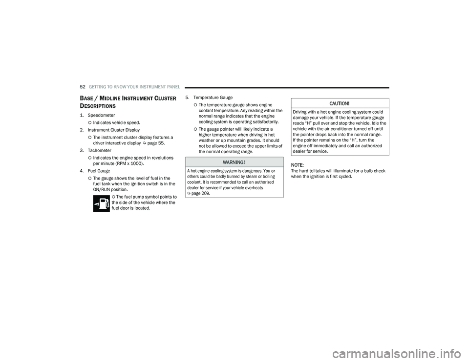
1. Speedometer
Indicates vehicle speed.
2. Instrument Cluster Display
The instrument cluster display features a
driver interactive display Ú page 55.
3. Tachometer
Indicates the engine speed in revolutions
per minute (RPM x 1000).
4. Fuel Gauge
The gauge shows the level of fuel in the
fuel tank when the ignition switch is in the
ON/RUN position.
The fuel pump symbol points to
the side of the vehicle where the
fuel door is located. 5. Temperature Gauge
The temperature gauge shows engine
coolant temperature. Any reading within the
normal range indicates that the engine
cooling system is operating satisfactorily.
The gauge pointer will likely indicate a
higher temperature when driving in hot
weather or up mountain grades. It should
not be allowed to exceed the upper limits of
the normal operating range.
NOTE:The hard telltales will illuminate for a bulb check
when the ignition is first cycled.
WARNING!
A hot engine cooling system is dangerous. You or
others could be badly burned by steam or boiling
coolant. It is recommended to call an authorized
dealer for service if your vehicle overheats
Ú
page 209.
CAUTION!
Driving with a hot engine cooling system could
damage your vehicle. If the temperature gauge
reads “H” pull over and stop the vehicle. Idle the
vehicle with the air conditioner turned off until
the pointer drops back into the normal range.
If the pointer remains on the “H”, turn the
engine off immediately and call an authorized
dealer for service.
22_VF_OM_EN_USC_t.book Page 52
Page 55 of 268
GETTING TO KNOW YOUR INSTRUMENT PANEL53
INSTRUMENT CLUSTER
3
22_VF_OM_EN_USC_t.book Page 53
Page 56 of 268

54GETTING TO KNOW YOUR INSTRUMENT PANEL
INSTRUMENT CLUSTER DESCRIPTIONS
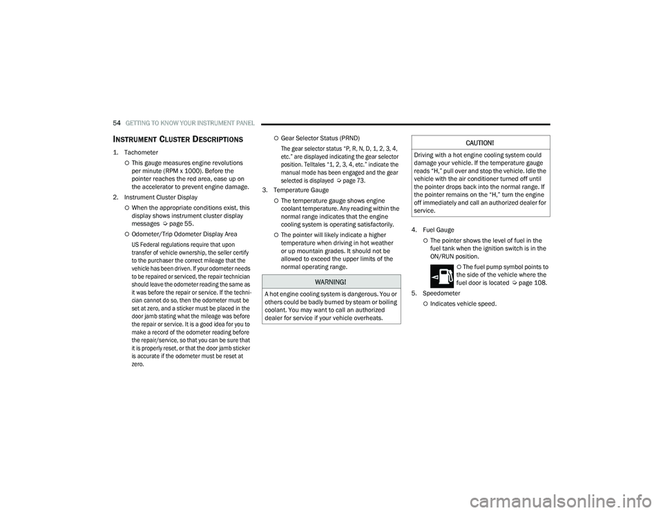
1. Tachometer
This gauge measures engine revolutions
per minute (RPM x 1000). Before the
pointer reaches the red area, ease up on
the accelerator to prevent engine damage.
2. Instrument Cluster Display
When the appropriate conditions exist, this
display shows instrument cluster display
messages Ú page 55.
Odometer/Trip Odometer Display Area
US Federal regulations require that upon
transfer of vehicle ownership, the seller certify
to the purchaser the correct mileage that the
vehicle has been driven. If your odometer needs
to be repaired or serviced, the repair technician
should leave the odometer reading the same as
it was before the repair or service. If the techni -
cian cannot do so, then the odometer must be
set at zero, and a sticker must be placed in the
door jamb stating what the mileage was before
the repair or service. It is a good idea for you to
make a record of the odometer reading before
the repair/service, so that you can be sure that
it is properly reset, or that the door jamb sticker
is accurate if the odometer must be reset at
zero.
Gear Selector Status (PRND)
The gear selector status “P, R, N, D, 1, 2, 3, 4,
etc.” are displayed indicating the gear selector
position. Telltales “1, 2, 3, 4, etc.” indicate the
manual mode has been engaged and the gear
selected is displayed
Ú
page 73.
3. Temperature Gauge
The temperature gauge shows engine
coolant temperature. Any reading within the
normal range indicates that the engine
cooling system is operating satisfactorily.
The pointer will likely indicate a higher
temperature when driving in hot weather
or up mountain grades. It should not be
allowed to exceed the upper limits of the
normal operating range. 4. Fuel GaugeThe pointer shows the level of fuel in the
fuel tank when the ignition switch is in the
ON/RUN position.
The fuel pump symbol points to
the side of the vehicle where the
fuel door is located Ú page 108.
5. Speedometer
Indicates vehicle speed.
WARNING!
A hot engine cooling system is dangerous. You or
others could be badly burned by steam or boiling
coolant. You may want to call an authorized
dealer for service if your vehicle overheats.
CAUTION!
Driving with a hot engine cooling system could
damage your vehicle. If the temperature gauge
reads “H,” pull over and stop the vehicle. Idle the
vehicle with the air conditioner turned off until
the pointer drops back into the normal range. If
the pointer remains on the “H,” turn the engine
off immediately and call an authorized dealer for
service.
22_VF_OM_EN_USC_t.book Page 54