Page 177 of 337

T
T
r
r a�1c
a�1c Sign Assist
Sign Assist F
F
unction of
unction of Tr
Tra�1c
a�1c Sign Assist
Sign Assist
Tr a�1c Sign Assist aids youby displaying de tected
speed limits and overtaking restrictions in the
inst rument cluster.
Since Tra�1c Sign Assist also uses the data stored
in the navigation system, it can also update the
display without de tecting tra�1c signs.
The camera also de tects tra�1c signs with a restric-
tion indicated byan additional sign (e.g. when
we t).
% Tra�1c signs are only displ ayed with there stric-
tion indicated byan additional sign in thefo l-
lowing cases:
R the tra�1c signs must be obser ved with the
re striction
R the system is unable toclear lyde term ine
whe ther there striction applies
If th e system de tects that you are driving onto a
section of road in the wrong direction of tr avel, it
triggers a warning. This function is not available in
all countries.
Tr a�1c Sign Assist is only an aid and is not alw ays
able tocor rectly display speed limits and overtak-
ing restrictions. The actual tra�1c signs always
ha ve priority overth eTra�1c Sign Assist displ ay.
Obser vethe no tes on driving systems and your
re sponsibility; you may otherwise failto recognise
dangers (/ page 152).
Ins
Ins tr trument clust
ument clust er display
er display
The Tra�1c Sign Assist displ ayappears in theAssis-
tance graphic menu ofthe on-board computer
(/ page 184). 1
Perm issible speed
2 Perm issible speed when there is a restriction
3 Additional sign with restriction (e xample:
unknown restriction)
If Tra�1c Sign Assist is not available or cann ot
de term ine the maximum permissible speed, thefo
llowing display appears in the assistance
gr aphic: Syst
Syst
em limits
em limits
The system may be impaired or may not function in
th efo llowing situations:
R Ifth ere is poor visibility, e.g. due toinsu�1cient
illumination of the road, highly variable shade
conditions, or due torain, sno w,fog or heavy
spr ay.
R Ifth ere is glare, e.g. from oncoming tra�1c,
direct sunlight or re�0ections.
R Ifth ere is dirt on the windscreen in the vicinity
of the multifunction camera or if the camera is
misted up, damaged or obscured.
R Ifth e tra�1c signs are hard todetect, e.g. due
to dirt or sno w,or because they are co vered,
or due toinsu�1cient lighting.
R Ifth ere are ambiguous signs, e.g. tra�1c signs
in road works or adjacent lanes.
R Ifth e information in the navigation system's
digital map is incor rect or out-of-date.
A
A ctiv ctiv ating/deactiv
ating/deactiv ating t
ating the
heTr
Tra�1c
a�1c Sign Assist
Sign Assist
w
w ar
ar ning function
ning function
On-board computer
4 ò 5
Settings 5
Assistance
5 Traffic Sign Assist #
T
To activ
o activ at
ate/deactiv
e/deactiv at
ate:
e: press thea button.
When thewa rning function is active and you pass a
tra�1c sign, the inst rument cluster sho ws the tra�1c
re gulations (speed limit and overtaking restriction)
fo r �/ve seconds. The pr evious menu then reap-
pears automaticall y.
The wrong-w aywarning remains active if you deac-
tivate thewa rning function of Tra�1c Sign Assist. Blind Spo
Blind Spo
t Assist
t Assist F
F
unction of Blind Spo
unction of Blind Spo t Assist
t Assist
Blind Spot Assist uses two lateral, rear-facing radar
sensors tomonitor the area directly next toand on
th e side behind theve hicle. 174
174
Driving and parking
Page 178 of 337

&
W
WARNI NG
ARNI NGRisk of accident despite Blind
Spot Assist
Blind Spot Assist does not react toeither sta-
tionary objects or vehicles approaching and
ov ertaking you at a greatly di�.erent speed.
Blind Spot Assist cannot warndrivers in these
situations. #
Always pay careful attention tothe tra�1c
situation and maintain a safe distance at
th e side of theve hicle. Obser
vethe no tes on driving systems and your
re sponsibility; you may otherwise failto recognise
dangers (/ page 152).
If a vehicle is de tected abo vespeeds of appr ox-
imately 12 km/h and this vehicle subsequently
enters the monitoring range directly next toyour
ve hicle, thewa rning lamp in the outside mir ror
lights up red.
If a vehicle is de tected close toyour vehicle in the
lateral monitoring range and you switch on the turn
signal indicator in the cor responding direction, a
wa rning tone sounds. The redwa rning lamp in the
outside mir ror �0ashes. If the turn signal indicator
re mains switched on, all other de tected vehicles
are indicated only bythe �0ashing of there dwa rn-
ing lamp.
When youove rtake a vehicle, thewa rning only
occurs if the di�.erence in speed is less than
appr oximately 20 km/h.
Syst Syst em limits
em limits
Blind Spot Assist may be limited in thefo llowing
situations:
R ifth ere is dirt on the sensors or the sensors
are obscured
R ifth ere is poor visibility, e.g. due tofog, heavy
ra in, snow or spr ay
R if nar row vehicles are within the monitoring
ra nge, e.g. bic ycles
R ifth ero ad has very wide or very nar row lanes
R ifve hicles are not driving in the middle of their
lane
Wa rnings may be issued in er ror when driving
close tocrash bar riers or similar solid lane bor-
ders. Warnings may be inter rupted when driving
alongside long vehicles, forex ample lor ries, for a
prolonged time.
Blind Spot Assist is not operational when reve rse
ge ar is engaged. If
yo u couple up a trailer, make sure that you ha ve
cor rectly es tablished the electrical connection.
Blind Spot Assist is then deactivated and theBlind
Spot Assist currently unavailable See Owner's
Manual message appears in the inst rument cluster
displa y.
A
A ctiv ctiv ating/deactiv
ating/deactiv ating Blind Spo
ating Blind Spo t Assist
t Assist
On-board computer:
4 ò 5
Settings 5
Assistance
5 Blind Spot Assist #
T
To activ
o activ at
ate/deactiv
e/deactiv at
ate:
e: press thea button.
When Blind Spot Assist is activated, grey radar
wa ves propagating towa rdthere ar appear next to
th eve hicle in the assistance graphic in the inst ru-
ment cluster displa y.Ifyo u drive faster than
12 km/h with Blind Spot Assist activated, the
ra dar waves in the assistance graphic are dis-
pla yed in green. Blind Spot Assist is ready for use.
If yo u switch on theve hicle while Blind Spot Assist
is activated, thewa rning lamps in the outside mir-
ro rs light up for appr ox. 1.5 seconds. R
R
ear Cr
ear Cr oss
ossTr
Tra�1c
a�1c Alert
Alert F
F
unction of R
unction of R ear Cr
ear Cross
oss Tr
Tra�1c
a�1c Alert
Alert
% The system is only available forve hicles with
Blind Spot Assist.
The system uses thera dar sensors in the bumper.
This wayth e area adjacent totheve hicle is contin-
ually moni tore d. If thera dar sensors are obscured
by vehicles or other objects, de tection is not possi-
ble.
% Also read the no tes on Blind Spot Assist
(/ page 174).
The system can warnof crossing tra�1c when
re ve rsing out of a parking space. If the system
de tects a vehicle, thewa rning lamp in the outside
mir ror on the cor responding side lights up red. In a
critical situation, an additional warning tone
sounds.
The Rear Cross Tra�1c Ale rtfunction is active
under thefo llowing conditions:
R Blind Spot Assist is activated.
R Reversege ar is engaged or theve hicle is
re ve rsing at walking pace.
The Rear Cross Tra�1c Ale rtfunction is una vailable
when driving with a trailer. Driving and parking
175
175
Page 179 of 337

Lane K
Lane K
eeping Assist
eeping Assist F
F
unction of Lane K
unction of Lane K eeping Assist
eeping Assist
Lane Keeping Assist ser vesto protect you against
unintentionally leaving your lane. You are also
wa rned bya noticeable vib ration in the steering
wheel and bythe status symbol �0ashing in the
inst rument cluster. Lane Keeping Assist is only an
aid and is not intended tokeep theve hicle in the
lane without the driver's cooperation.
Obser vethe no tes on driving systems and your
re sponsibility; you may otherwise failto recognise
dangers (/ page 152).
The function is available in the speed range
between 60 km/h and 200 km/h.
The warning is issued when thefo llowing condi-
tions are met at the same time:
R If Lane Keeping Assist de tects lane markings.
R If a front wheel drives over lane markings.
To ensure that you are warned only when neces-
sary and in good time if you cross the lane mar k-
ing, the system de tects cer tain conditions and
wa rnsyo u accordingl y.
The warning vibration occurs earlier under thefo l-
lowing conditions:
R you approach the outer lane marking on a
bend.
R thero ad has very wide lanes, e.g. a mo torw ay.
R the system de tects solid lane markings.
The warning vibration occurs later under thefo l-
lowing conditions:
R you are driving on a road with nar row lanes.
R you cut the corner on a bend.
Syst
Syst em limits em limits
The system may be impaired or may not function in
th efo llowing situations:
R Ifth ere is poor visibility, e.g. due toinsu�1cient
illumination of the road, if there are highly vari-
able shade conditions or in rain, sno w,fog or
spr ay.
R Glare from oncoming tra�1c, direct sunlight or
re �0ections.
R Thereis dirt on the windscreen in the vicinity
of the multifunction camera or the camera is
misted up, damaged or obscured.
R No or se veral unclear lane markings are pres-
ent for one lane, e.g. in a construction area. R
Ifth e lane markings are wornawa y,dark or
co vered up.
R Ifth e distance totheve hicle in front is too
short and thus the lane markings cannot be
de tected.
R The lane markings change quickl y,e.g. lanes
branch o�., cross one ano ther or mer ge.
R The ca rriag ewa y isvery nar row and winding.
A
A ctiv ctiv ating/deactiv
ating/deactiv ating Lane K
ating Lane Keeping Assist
eeping Assist #
Press theÇ button.
If th e indicator lamp in the button is lit, Lane
Ke eping Assist is activated. If all conditions
ha ve been satis�/ed, there may be a warning.
If Lane Keeping Assist is activated and you are
driving at speeds abo ve60 km/h and lane
markings are de tected, the lines in the assis-
ta nce display menu of the on-board computer
are shown in green. Lane Keeping Assist is
re ady for use.
When the system switches over, theLane
Keeping Assist on orLane Keeping Assist off
message is shown brie�0y in the inst rument
cluster displa y.
% You can �/nd information on the assistance
gr aphic menu under "Assistance graphic"
(/ page 184).
Se
Se tting t
tting t he sensitivity of Lane K
he sensitivity of Lane K eeping Assist
eeping Assist
On-board computer:
4 ò 5
Settings 5
Assistance
5 Lane Keeping Assist #
Select theStandard orAdaptive setting. 176
176
Driving and parking
Page 180 of 337

In
theStandard setting, no warning vibration
occurs in thefo llowing situations:
R you operate the turn signal in the cor respond-
ing direction. In this event, thewa rnings are
suppressed for a cer tain period of time.
R a driving saf ety system in tervenes or regulates,
such as ABS, BAS or ESP ®
.
In theAdaptive setting,there will also be no warn-
ing vibration in thefo llowing situations:
R you accelerate hard, e.g. kickdown.
R you brake hard.
R you steer activel y,e.g. swer vetoavo id an
obstacle or change lane quickl y.
R you cut the corner on a sharp bend. T
T
r
railer oper
ailer oper ation
ation N
No
ot
tes on tr
es on tr ailer oper
ailer oper ation
ation &
W
WARNING
ARNING Risk of accident and injury if
th eto ngue weight is exceeded
The car rier system may de tach from theve hi-
cle, thereby endangering other road users. #
Always comply with the permissible
to ngue weight when using a car rier. Yo
u can �/n dspeci�/cations rega rding the ball neck
on the trailer's identi�/cation plate. You can �/nd
speci�/cations rega rding the trailer on theto wing
ve hicle's identi�/cation plate and in theTe ch nical
Data (/ page 279).
Yo u can attach car rier systems such as a bicycle
ra ck or load-bearing implement tothe ball nec k.
When using car rier systems on the ball nec k, the
maximum load capacity is 75 kg.
If th e trailer coupling is de tach able, it is essential
to comply with the operating inst ructions of the
trailer coupling manufactu rer.
Place your vehicle/trailer combination on sur faces
th at are as even as possible and secure it against
rolling away (/ page 150). Couple and uncouple
th e trailer carefull y. No
tethefo llowing rega rding theto ngue weight:
R Make full use of the maximum tongue weight,
where possible.
R Neverfa ll below a legally prescribed minimum
to ngue weight; theto ngue weight must alw ays
be positive.
R Do not exceed or fall below the permissible
to ngue weights – this must be obser ved during
loading and unloading of the trailer.
Do not exceed thefo llowing values:
R Perm itted braked or unbraked towing capacity
The maximum permissible towing capacity for
unbraked trailers is 750 kg.
R Perm issible rear axle load of theto wing vehicle
R Perm issible gross weight of theto wing vehicle
R Perm issible gross weight of the trailer
R Perm issible gross combination weight
R Maximum permissible speed of the trailer
The releva nt permitted values, which must not be
ex ceeded, can be found in thefo llowing places:
R Inyour vehicle documents
R Onthe identi�/cation plate of the trailer hitch
R Onthe trailer's identi�/cation plate
R Ontheve hicle identi�/cation plate
If th ere are discrepancies between theva lues, the
lo we st one shall appl y.
Before driving o�., ensure thefo llowing:
R The tyre pressure on there ar axle of theto w-
ing vehicle has been set forth e maximum load.
R The headlamps ha vebeen set cor rectl y.
Comply with the maximum permissible speed of
80 km/h or 100 km/h, even in countries in which
higher speeds are permitted forve hicle/trailer
combinations.
% During trailer operation, remember that
PA RKTRONIC is available only toa limi ted
ex tent, if at all.
% The height of the ball head will change
depending on theve hicle's load. In this case,
use a trailer with a height-adjustable dr awbar. Driving and parking
177
177
Page 181 of 337

V
V
ehicles wit
ehicles wit h a det
h a detac
achable tr
hable tr ailer coupling
ailer coupling
* NO
NOTE
TEIncreased risk of damage toprop-
erty due toattached ball neck #
When the trailer is not coupled or the
bicycle rack is attached, fold in the ball
nec k. Re
duce therisk of damage tothe trailer coupling
and contribute toenvironmental pr otection. If you
do not need the ball nec k,remo veit from the ball
neck mount and �/t its co ver in there ar bumper
(/ page 178). Only with the co ver �/t ted can the
emission values indicated forre al operation be
achie ved.
% During trailer operation, the permissible gross
ve hicle weight is increased by100 kg forve hi-
cles registered as passenger vehicles. The
maximum permissible rear axle load must be
obser ved. F
F
itting t
itting t he cov
he cov er f
er for tr
or tr ailer coupling
ailer coupling #
Insert the co ver �0ush into there cess on the
re ar bumper and press it upwards against the
bumper co vering at the latching points on the
outside right and le�T. #
Turn fastene rsfrom position 1toposition
2. #
Ensure that thefa stene rsare fully engaged and
�/rmly in position 2. A
A
tt
tt ac
ac hing t
hing t he ball neck
he ball neck &
W
WARNING
ARNING Risk of accident and injury due
to incor rectly ins talled and secured ball
neck
If th e ball neck is not engaged, it may become
loose while theve hicle is in motion and endan-
ge rot her road users. #
Engage the ball neck as described and
ensure that the ball neck is securely
installed. &
W
WARNING
ARNING Danger of accident due tonon-
engaged ball coupling
If th e ball coupling has not engaged, the trailer
can become de tach ed. #
Always engage the ball coupling as
described and ensure that it is securely
ins talled. R
R
eq
eq uir
uir ements:
ements:
R The trailer hitch key is available. #
Notethe number of theke yth at belongs tothe
ball neck of the trailer hitch.
Wi th th is number, you will receive a replace-
ment key at a Mercedes-Benz service centre.
% Depending on theve hicle equipment, the
holder forth e ball neck on theve hicle can be
pr otected with a co ver in the bumper. #
Release the two quick- re lease fastene rsforthe
co ver in the bumper and remo vethe co ver
( / page 178). #
Take the ball neck of the trailer hitch out of the
st ow age space on theright-hand side in the
re ar and st owthe co verawa y. #
Unlo cklock 6in handwheel 1with thekey.
Re d mark 3onthe handwheel must be
aligned with green area 2on ball neck 4
(�/tting position). 178
178
Driving and parking
Page 182 of 337

#
Ifre d mark 3is not aligned with green area
2, unlock lock 6in handwheel 1with the
key. #
Pull handwheel 1outwards. Turn red mark
3 into green area 2of ball neck 4until
handwheel 1engages. #
Slide ball neck 4vertically into the holder
until it audibly engages.
The ball neck will lock automaticall y.Green
mark 3on handwheel 1is aligned with
gr een area 2on ball neck 4.
Only if thegr een mark on the handwheel is
aligned with thegr een area on the ball neck is
th e ball neck securely engaged. #
Lock lock 6in handwheel 1with thekey. #
Remo vetheke y and place cap 5on lock 6.
The ball neck is securely installed only if the
ball neck can be loc ked and theke yre mo ved. #
Store the trailer hitch key in a safe place, e.g.
in theve hicle document wallet.
If yo u cannot remo vetheke y,the ball neck may be
dirty. #
Remo vethe ball neck (/ page 179) and clean
it (/ page 232).
If yo u still cannot lock the ball neck a�Ter cleaning
it, the trailer hitch is damaged. #
Remo vethe ball nec k.
Safe trailer operation is not gua ranteed. The
ball neck must no longer be used for trailer
operation. #
Have the trailer hitch checked at a quali�/ed
specialist workshop. R R
emo
emo ving t
ving t he ball neck
he ball neck R
R
eq
eq uir
uir ements:
ements:
R The trailer hitch key is available. #
Remo vecap 5from lock 6in handwheel
1. #
Unlock lock 6in handwheel 1with thekey. #
Hold ball neck 4in place. #
Pull handwheel 1outwards. Turn red mark
3 on handwheel 1into green area 2of
ball neck 4until handwheel 1engages. Pay
attention tothe pictog ram on handwheel 1. #
Pull ball neck 4out down wards. #
Ifth e ball neck is dirty, clean it (/ page 232).
% Depending on theve hicle equipment, the
holder forth e ball neck on theve hicle can be
pr otected with a co ver in the bumper. #
Store the ball neck with theke y inser ted in the
st ow age space on theright-hand side in the
re ar and remo vethe co verfo rth e ball neck
holder. #
Insert the co ver in the lo wer section of the
bumper and tighten the two quick- re lease fas-
te ners forth e co ver (/ page 178). Coupling/uncoupling a tr
Coupling/uncoupling a tr
ailer
ailer R
R
eq
eq uir
uir ements:
ements:
R The ball neck must be engaged in a securely
locked position.
Tr ailers with 7-pin plugs can be connected tothe
ve hicle using thefo llowing adap ters:
R Adapter plug
R Adapter cable
Coupling a tr Coupling a tr ailer
ailer
* NO NOTE TEDamage tothe star ter battery due
to full dis charge Charging
the trailer battery using the po wer
supply of the trailer can damage the star ter
batter y. #
Do not use theve hicle's po wer supply to
ch arge the trailer batter y. 1
Eyelet for break away cable Driving and parking
179
179
Page 183 of 337

The
eyelet on the ball neck is used exclusively for
attaching the trailer break away cable. You must
not attach a tow rope, a tow bar or anything similar
to theey elet. The eyelet has not been designed for
such a load and may tear. #
Shi�T the transmission toposition j. #
Apply theve hicle's parking brake. #
Close all the doors. #
Position the trailer on a le vel sur face behind
th eve hicle.
% The height of the ball head will change
depending on theve hicle's load. In this case,
use a trailer with a height-adjustable dr awbar. #
Couple up the trailer. #
T
To inst
o inst all an adapt
all an adapt er
er:
:open the co ver of the
soc ket. #
Inse rtplug 2with tab1 inthe soc ket's
gr oo ve 3 . #
Turn plug 2clockwise as far as it will go. #
Letthe co ver engage. #
Attach the cable tothe trailer with cable ties
(only in the case of adap ter cables). #
Make sure that the cable is alw ays slack for
ease of mo vement during cornering. #
Establish all electrical and other connections
to the trailer. In the process, attach the trailer's
break away cable totheey elet on the ball nec k. #
Check that the trailer's lighting system works
proper ly.
A trailer is de tected only if the electrical con-
nection is established cor rectly and the lighting
system is in working order. The function of
ot her systems also depends on this, e.g. ESP ®
,
PA RKTRONIC, Active Parking Assist, Blind Spot
Assist or Lane Keeping Assist. Even if
the trailer is connected cor rectl y,a mes-
sage may ne vertheless appear on the inst rument
cluster display in thefo llowing cases:
R LEDs ha vebeen ins talled in the trailer's lighting
system.
R The cur rent has fallen below the trailer lighting
system's minimum cur rent (50 mA)
% You can connect accessories up toa maxi-
mum of 240 W tothe permanent po wer sup-
pl y. #
Remo veobjects or devices that pr event the
trailer from rolling, e.g. choc ks. #
Release the trailer's parking brake.
U
Uncoupling a tr ncoupling a tr ailer
ailer &
W
WARNING
ARNING Risk of being crushed and
becoming trapped when uncoupling a
trailer
When uncoupling a trailer with an engaged
inertia-activated brake, your hand may become
trapped between theve hicle and the trailer
dr aw bar. #
Do not uncouple trailers with an engaged
overrun brake. *
N NOOTE
TE Damage when uncoupling in a state
of ove rrun Uncoupling in a state of
overrun can damage
th eve hicle. #
Do not uncouple trailers with an engaged
overrun brake. #
Shi�T the transmission toposition j. #
Apply theve hicle's parking brake. #
Close all the doors. #
Apply the trailer's parking brake. #
Further secure the trailer against rolling away
with a wheel chock or similar object. #
Remo vethe trailer cables and saf etych ains. #
Uncouple the trailer. 180 180
Driving and parking
Page 184 of 337

1 Speedome ter
2 Display
3 Rev counter
4 Coolant temp erature display
5 Fuel le vel
Spe")
Ov
Ov
er
ervie
vie w of t
w of t he ins
he ins tr
trument clust
ument clust er
er Inst
rument cluster (e xample)
1 Speedome ter
2 Display
3 Rev counter
4 Coolant temp erature display
5 Fuel le vel
Speedom et
Speedom eter
er
In vehicles with Active Distance Assist DISTRONIC,
th ere are illuminated segments on the speedome-
te r dial.
These segments show you what speed range is
av ailable:
R Variable limi ter activated (/ page 158)
The segments light up from the start of the
scale tothe selected limit speed.
R Active Distance Assist DISTRONIC switched on
(/ page 161)
One or two segments light up in the sa ved
speed range.
R Active Distance Assist DISTRONIC de tects a
ve hicle in front.
The segments light up from the speed of the
ve hicle in front up tothe sa ved speed.
Yo u can show the speed as a digital speedome ter
on the display as well.
If yo uch ange your vehicle's wheel size, check its
assignment tothe wheel size group (/ page 260).
If th e assignment changes without recoding the
cont rol units in theve hicle, the speedome ter will
not display the speed accuratel y.The cur rent vehi-
cle speed may then be higher than the speed
shown bythe speedome ter. Driving and driving
saf ety systems may then be operationally impaired
or may de tect a malfunction and switch them-
sel ves o�..
In some countries, an audible signal will sound
and/or a message will appear on the display when th
eve hicle reaches the maximum speed permitted
by law, e.g. at 120 km/h.
R
R e
ev count
v count er
er
* NO
NOTE
TEEngine damage due tomaximum
engine speed being exceeded If
th e maximum permissible engine speed is
ex ceeded, the engine may be damaged. #
Avoid driving in there d speed range
(danger zone). Outside t
Outside t
em
emper
per atur
atur e display
e display
Yo u should pay special attention toroad conditions
when temp eratures are around freezing point.
The outside temp erature is shown on the inst ru-
ment cluster display (/ page 183).
Changes in the outside temp erature will be dis-
pla yed a�Ter a short dela y.
Coolant t
Coolant t em
emper
per atur
atur e display
e display &
W
WARNING
ARNING Risk of burns when opening the
bonnet
If yo u open the bonnet in theev ent of an over-
heated engine or �/re in the engine compart-
ment, thefo llowing situations may occur:
R You may come into contact with hot gases.
R You may come into contact with other
escaping hot operating �0uids. #
Before opening the bonnet, allow the
engine tocool down. #
Intheev ent of a �/re in the engine com-
partment, keep the bonnet closed and
call the �/re service. The coolant
temp erature display is located within
th e inst rument cluster's rev counter.
During normal driving and if the coolant le vel is
cor rect, the display is permitted torise to120°C. Ov
Ov
er
ervie
vie w and oper
w and oper ation of t
ation of the on-boar
he on-boar d com-
d com-
put
put er
er &
W
WARNING
ARNING Risk of distraction due toinfor-
mation systems and communications
equipment
If yo u operate information systems and com-
munications equipment integ rated in theve hi-
cle when driving, you could be distracted from Instrument cluster and on-board computer
181 181
 1
1 2
2 3
3 4
4 5
5 6
6 7
7 8
8 9
9 10
10 11
11 12
12 13
13 14
14 15
15 16
16 17
17 18
18 19
19 20
20 21
21 22
22 23
23 24
24 25
25 26
26 27
27 28
28 29
29 30
30 31
31 32
32 33
33 34
34 35
35 36
36 37
37 38
38 39
39 40
40 41
41 42
42 43
43 44
44 45
45 46
46 47
47 48
48 49
49 50
50 51
51 52
52 53
53 54
54 55
55 56
56 57
57 58
58 59
59 60
60 61
61 62
62 63
63 64
64 65
65 66
66 67
67 68
68 69
69 70
70 71
71 72
72 73
73 74
74 75
75 76
76 77
77 78
78 79
79 80
80 81
81 82
82 83
83 84
84 85
85 86
86 87
87 88
88 89
89 90
90 91
91 92
92 93
93 94
94 95
95 96
96 97
97 98
98 99
99 100
100 101
101 102
102 103
103 104
104 105
105 106
106 107
107 108
108 109
109 110
110 111
111 112
112 113
113 114
114 115
115 116
116 117
117 118
118 119
119 120
120 121
121 122
122 123
123 124
124 125
125 126
126 127
127 128
128 129
129 130
130 131
131 132
132 133
133 134
134 135
135 136
136 137
137 138
138 139
139 140
140 141
141 142
142 143
143 144
144 145
145 146
146 147
147 148
148 149
149 150
150 151
151 152
152 153
153 154
154 155
155 156
156 157
157 158
158 159
159 160
160 161
161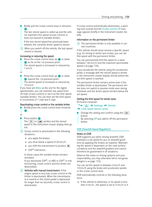 162
162 163
163 164
164 165
165 166
166 167
167 168
168 169
169 170
170 171
171 172
172 173
173 174
174 175
175 176
176 177
177 178
178 179
179 180
180 181
181 182
182 183
183 184
184 185
185 186
186 187
187 188
188 189
189 190
190 191
191 192
192 193
193 194
194 195
195 196
196 197
197 198
198 199
199 200
200 201
201 202
202 203
203 204
204 205
205 206
206 207
207 208
208 209
209 210
210 211
211 212
212 213
213 214
214 215
215 216
216 217
217 218
218 219
219 220
220 221
221 222
222 223
223 224
224 225
225 226
226 227
227 228
228 229
229 230
230 231
231 232
232 233
233 234
234 235
235 236
236 237
237 238
238 239
239 240
240 241
241 242
242 243
243 244
244 245
245 246
246 247
247 248
248 249
249 250
250 251
251 252
252 253
253 254
254 255
255 256
256 257
257 258
258 259
259 260
260 261
261 262
262 263
263 264
264 265
265 266
266 267
267 268
268 269
269 270
270 271
271 272
272 273
273 274
274 275
275 276
276 277
277 278
278 279
279 280
280 281
281 282
282 283
283 284
284 285
285 286
286 287
287 288
288 289
289 290
290 291
291 292
292 293
293 294
294 295
295 296
296 297
297 298
298 299
299 300
300 301
301 302
302 303
303 304
304 305
305 306
306 307
307 308
308 309
309 310
310 311
311 312
312 313
313 314
314 315
315 316
316 317
317 318
318 319
319 320
320 321
321 322
322 323
323 324
324 325
325 326
326 327
327 328
328 329
329 330
330 331
331 332
332 333
333 334
334 335
335 336
336