Page 17 of 136
Description
2-3
2
EAU10431
Controls and instruments
1
2
4
5
6
7
8
3
1. Clutch lever (page 4-32)
2. Left handlebar switches (page 4-3)
3. Main switch/steering lock (page 4-2)
4. Instrument panel (page 4-5, 4-9)
5. Front brake fluid reservoir (page 7-25)
6. Right handlebar switches (page 4-3)
7. Brake lever (page 4-33)
8. Throttle grip
UB3LE0E0.book Page 3 Tuesday, July 23, 2019 12:05 PM
Page 18 of 136
Yamaha Ride Control is a system that
incorporates numerous sensors and
controls to support an improved riding
experience. The vehicle senses an")
Special features
3-1
3
EAU6629B
YRC (Yamaha Ride Control)Yamaha Ride Control is a system that
incorporates numerous sensors and
controls to support an improved riding
experience. The vehicle senses and
can react to forces along the longitudi-
nal (front-to-back), lateral (left-to-right),
and vertical (up-and-down) axes. Lean
angle and G-force accelerations are
also detected. This information is pro-
cessed multiple times a second and
the related physical systems are auto-
matically adjusted as necessary. The
following functions represent individual
YRC items which can be turned on/off
or adjusted to suit various riders and
riding conditions. For setting details,
see pages 4-11 and 4-16.
WARNING
EWA18221
The Yamaha Ri de Control (YRC) sys-
tem is not a su bstitute for the use of
proper ri din g techniques or the ex-
pertise of the operator. This system
cannot prevent loss of control
caused b y ri der errors such as trav-
elin g faster than warranted b y roa d
an d traffic con ditions, inclu din g loss of traction
due to excessive spee d
when enterin g turns, when acceler-
atin g har d at a sharp lean an gle, or
while brakin g, an d it cannot prevent
front wheel slip or front wheel lift. As
with any motorcycle, always ri de
within in your limits, be aware of sur-
roun din g con ditions, an d ri de ap-
propriately for those con ditions.
Become thorou ghly familiar with the
way the motorcycle han dles with
various YRC settin gs before at-
temptin g more a dvance d maneu-
vers.
PWR
The power delivery mode system con-
sists of four different control maps
which regulate throttle valve opening in
relation to the degree of throttle grip
operation, thus providing you with a
selection of modes to fit your prefer-
ences and the riding environment. TCS
The traction control system helps
maintain traction when accelerating. If
sensors detect that the rear wheel is
starting to slip (uncontrolled spinning),
the traction control system assists by
regulating engine power as needed un-
til traction is restored. The traction con-
trol system indicator/warning light
flashes to let the rider know that trac-
tion control has engaged.
1. PWR 1
2. PWR 2
3. PWR 3
4. PWR 4
5. Throttle valve opening
6. Throttle grip operation
5
64
3 2
1
UB3LE0E0.book Page 1 Tuesday, July 23, 2019 12:05 PM
Page 19 of 136

Special features
3-2
3
This traction control system automati-
cally adjusts according to the vehicle’s
lean angle. To maximize acceleration,
when the vehicle is upright a less
amount of traction control is applied.
When cornering, a greater amount of
traction control is applied.
TIP
The traction control system may
engage when the vehicle travels
over a bump.
You may notice slight changes in
engine and exhaust sounds when
the traction control or other YRC
systems engage.
When TCS is turned off, SCS,
LCS, and LIF are also turned off
automatically.
WARNING
EWA15433
The traction control system is not a
substitute for ri din g appropriately
for the con ditions. Traction control
cannot prevent loss of traction d ue
to excessive spee d when enterin g
turns, when acceleratin g har d at a
sharp lean an gle, or while brakin g,
an d cannot prevent front wheel slip-
pin g. As with any vehicle, approach
surfaces that may be slippery with
caution an d avoi d especially slip-
pery surfaces.When the key is turned to “ON”, the
traction control system automatically
turns on. The traction control system
can be turned on or off manually only
when the key is in the “ON” position
and the motorcycle is stopped.TIPTurn the traction control system off to
help free the rear wheel if the motorcy-
cle gets stuck in mud, sand, or other
soft surfaces.
NOTICE
ECA16801
Use only the specifie d tires. (See
pa ge 7-19.) Usin g different size d
tires will prevent the traction control
system from controllin g tire rotation
accurately.SCS
The slide control system regulates en-
gine power output when a sideward
slide is detected in the rear wheel. It
adjusts power output based on data
from the IMU. This system supports
the TCS to contribute to a smoother
ride.
EBM
The engine brake management system
reduces engine torque when deceler-
ating. The fuel injection, ignition timing,
and electronic throttle valve are elec-
tronically adjusted by the ECU. There
are 3 settings to suit the track, riding
conditions, or your personal prefer-
ence.
TCS
UB3LE0E0.book Page 2 Tuesday, July 23, 2019 12:05 PM
Page 20 of 136

Special features
3-3
3
WARNING
EWA20880
Make sure the engine has sufficient-
ly slowe d b efore shiftin g to a lower
g ear. En gag in g a lower gear when
the en gine speed is too high coul d
make the rear wheel lose traction.
This coul d cause loss of control, an
acci dent an d injury. It coul d also
cause en gine or d rivetrain damag e.
LCS
The launch control system helps the
rider achieve smooth and swift launch-
es from the starting grid. It keeps en-
gine speed from rising when the
throttle grip is fully turned. The LCS
regulates engine power output in con-
junction with the TCS and LIF systems
for optimal traction and reduced wheel
lift.NOTICE
ECA22950
Even when usin g LCS, the clutch le-
ver must b e released g ra dually to
avoi d clutch damag e.TIPLCS is intended for track use only.QSS
The quick shift system allows for clutch
lever-less, electronically-assisted shift-
ing. When the sensor on the shift rod
detects the appropriate motion in the
shift pedal, engine power output is mo-
mentarily adjusted to allow for the gear
change to occur. QSS does not operate when the clutch
lever is pulled, therefore normal shifting
can be done even when QSS is set to
on. Check the QS indicator for current
status and usability information.
Upshiftin
g con ditions
Vehicle speed of at least 20 km/h
(12 mi/h)
Engine speed of at least 2200
r/min
Accelerating (open throttle)
Downshiftin g con ditions
Vehicle speed of at least 20 km/h
(12 mi/h)
Engine speed of at least 2000
r/min
Engine speed sufficiently away
from red zone
1. EBM1
2. EBM2
3. EBM3
4. Engine brake force
5. Engine r/min
1
2
3
4
5
QSS usability In
dica-
tor Situation
Upshifting OK Accelerating
Downshifting
OK Decelerating
QSS cannot be
used Stopped
QSS turned off Turned off
UB3LE0E0.book Page 3 Tuesday, July 23, 2019 12:05 PM
Page 21 of 136

Special features
3-4
3
Decelerating and throttle fully-
closed
TIPQS and QS can be individ-
ually set.
Shifting into or out of neutral must
be done using the clutch lever.LIF
The lift control system reduces the rate
at which the front wheel will continue to
rise during extreme acceleration, such
as during starts or out-of-corner exits.
When front-wheel lift is detected, en-
gine power is regulated to slow front-
wheel lift while still providing good ac-
celeration.
BC
The brake control system regulates hy-
draulic brake pressure for the front and
rear wheels when the brakes are ap-
plied and wheel lock is detected. This
system has two settings. BC1 is standard ABS, which adjusts
brake pressure based on vehicle
speed and wheel speed data. BC1 is
designed to engage and maximize
braking when the vehicle is upright.
BC2 uses additional data from the IMU
to regulate applied brake power when
cornering to suppress lateral wheel
slip.
WARNING
EWA20891
The
brake control system is not a
su bstitute for the use of proper ri d-
in g an d brakin g techniques. The
b rake control system cannot pre-
vent all loss of traction due to over- b
rakin g from excessive spee d, or
lateral wheel slip when brakin g on
slippery surfaces.
ERS (YZF-R1M)
The electronic racing suspension by
ÖHLINS
® features OBTi (objective-
based tuning interface) for simplified,
situation-focused setting changes of
the automatic suspension control
modes. In addition, there are manual
modes which offer a finely-tuneable
traditional suspension set-up. The ERS
system is controlled by the SCU which
can adjust the front and rear suspen-
sion’s compression stroke and re-
bound stroke damping forces
independently. The automatic modes
will adjust suspension damping forces
based on running conditions.
ABS
BC1/BC2 BC2 BC2
UB3LE0E0.book Page 4 Tuesday, July 23, 2019 12:05 PM
Page 22 of 136
Special features
3-5
3
EAU66313
GlossaryABS - Anti-lock Brake System
ABS ECU - Anti-lock Brake System
Electronic Control Unit
BC - Brake Control
CCU - Communication Control Unit
EBM - Engine Brake Management
ECU - Engine Control Unit
ERS - Electronic Racing Suspension
GPS - Global Positioning System
IMU - Inertial Measurement Unit
LCS - Launch Control System
LIF - Lift Control System
PWR - Power delivery mode
QS - Quick Shift
QSS - Quick Shift System
SC - Stability Control
SCS - Slide Control System
SCU - Suspension Control Unit
TCS - Traction Control System
YRC - Yamaha Ride ControlUB3LE0E0.book Page 5 Tuesday, July 23, 2019 12:05 PM
Page 23 of 136
Special features
3-6
3
EAU66911
YRC functions visual gui de
BC2
BC1/BC2 EBM
1. Start
2. Acceleration
3. Braking
4. Apex
5. Exit
6. Straightaway
UB3LE0E0.book Page 6 Tuesday, July 23, 2019 12:05 PM
Page 24 of 136

Instrument and control functions
4-1
4
EAU1097A
Immo bilizer systemThis vehicle is equipped with an immo-
bilizer system to help prevent theft by
re-registering codes in the standard
keys. This system consists of the fol-
lowing:
a code re-registering key
two standard keys
a transponder (in each key)
an immobilizer unit (on the vehicle)
an ECU (on the vehicle)
a system indicator light (page 4-7) A
bout the keys
The code re-registering key acts like a
master key. It is used to register codes
in each standard key. Store the code
re-registering key in a safe place. Use
a standard key for daily operation.
When key replacement or re-register-
ing is necessary, bring the vehicle and
the master key along with any remain-
ing standard keys to a Yamaha dealer
to have them re-registered.
TIP Keep the standard keys as well as
keys of other immobilizer systems
away from the code re-registering
key.
Keep other immobilizer system
keys away from the main switch
as they may cause signal interfer-
ence.NOTICE
ECA11823
DO NOT LOSE THE CODE RE-REG-
ISTERING KEY! CONTACT YOUR
DEALER IMMEDIATELY IF IT IS
LOST! If the cod e re-registering key
is lost, the existin g stan dar d keys
can still be used to start the vehicle. However, re
gisterin g a new stan-
d ar d key is impossi ble. If all keys
have been lost or damag ed , the en-
tire immo bilizer system must be re-
place d. Therefore, han dle the keys
carefully. Do not su bmerse in water.
Do not expose to hi gh tempera-
tures.
Do not place near ma gnets.
Do not place near items that
transmit electrical si gnals.
Do not han dle rou ghly.
Do not grin d or alter.
Do not disassem ble.
Do not put two keys of any im-
mo bilizer system on the same
key rin g.
1. Code re-registering key (red bow)
2. Standard keys (black bow)UB3LE0E0.book Page 1 Tuesday, July 23, 2019 12:05 PM
 1
1 2
2 3
3 4
4 5
5 6
6 7
7 8
8 9
9 10
10 11
11 12
12 13
13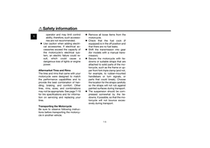 14
14 15
15 16
16 17
17 18
18 19
19 20
20 21
21 22
22 23
23 24
24 25
25 26
26 27
27 28
28 29
29 30
30 31
31 32
32 33
33 34
34 35
35 36
36 37
37 38
38 39
39 40
40 41
41 42
42 43
43 44
44 45
45 46
46 47
47 48
48 49
49 50
50 51
51 52
52 53
53 54
54 55
55 56
56 57
57 58
58 59
59 60
60 61
61 62
62 63
63 64
64 65
65 66
66 67
67 68
68 69
69 70
70 71
71 72
72 73
73 74
74 75
75 76
76 77
77 78
78 79
79 80
80 81
81 82
82 83
83 84
84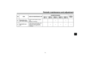 85
85 86
86 87
87 88
88 89
89 90
90 91
91 92
92 93
93 94
94 95
95 96
96 97
97 98
98 99
99 100
100 101
101 102
102 103
103 104
104 105
105 106
106 107
107 108
108 109
109 110
110 111
111 112
112 113
113 114
114 115
115 116
116 117
117 118
118 119
119 120
120 121
121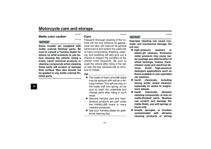 122
122 123
123 124
124 125
125 126
126 127
127 128
128 129
129 130
130 131
131 132
132 133
133 134
134 135
135
2. Left handlebar switches (page 4-3)
3. Main switch/steering lock (page 4-2)
4. Instrument panel (page")

