Page 65 of 136

Instrument and control functions
4-42
4
EAU66477
A djustin g the front forkNOTICE
ECA22472
Use extra care to avoi d scratch-
in g the ano dize d finish when
makin g suspension ad just-
ments.
To avoi d d amag ing the suspen-
sion’s internal mechanisms, do
not attempt to turn beyon d the
maximum or minimum settin gs.For YZF-R1
This model is equipped with adjustable
suspension. The spring preload, re-
bound damping force, and compres-
sion damping force of each leg can be
adjusted.
WARNING
EWA10181
Always a djust both fork le gs equally,
otherwise poor han dlin g an d loss of
sta bility may result.Sprin g preloa d
Turn the adjusting nut in direction (a) to
increase the spring preload. Turn the adjusting nut in direction (b) to
decrease the spring preload.
To set the spring preload, turn the ad-
juster in direction (b) until it stops, and
then count the turns in direction (a).
TIPWhen turning the spring preload ad-
juster in direction (a), it may turn be-
yond the stated specifications,
however such adjustments are ineffec-
tive and may damage the suspension.Re
boun d d ampin g force
Turn the adjusting bolt in direction (a)
to increase the rebound damping
force.
Turn the adjusting bolt in direction (b)
to decrease the rebound damping
force.
To set the rebound damping force, turn
the adjuster in direction (a) until it
stops, and then count the clicks in di-
rection (b).
1. Spring preload adjusting nut
Sprin g preloa d settin g:
Minimum (soft): 0 turn(s) in direction (a)
Standard: 6 turn(s) in direction (a)
Maximum (hard):
15 turn(s) in direction (a)
(b)
(a) 1
UB3LE0E0.book Page 42 Tuesday, July 23, 2019 12:05 PM
Page 66 of 136
, the 0 click
position and the 1 click position
may be the same.
When turning the damping for")
Instrument and control functions
4-43
4
TIP When turning the damping force
adjuster in direction (a), the 0 click
position and the 1 click position
may be the same.
When turning the damping force
adjuster in direction (b), it may
click beyond the stated specifica- tions, however such adjustments
are ineffective and may damage
the suspension.
Compression
dampin g force
Turn the adjusting bolt in direction (a)
to increase the compression damping
force.
Turn the adjusting bolt in direction (b)
to decrease the compression damping
force.
To set the compression damping
force, turn the adjuster in direction (a)
until it stops, and then count the clicks
in direction (b).
TIP When turning the damping force
adjuster in direction (a), the 0 click
position and the 1 click position
may be the same.
When turning the damping force
adjuster in direction (b), it may
click beyond the stated specifica-
tions, however such adjustments
are ineffective and may damage
the suspension.For YZF-R1M
This model is equipped with ÖHLINS
electronic racing suspension with gas
reservoir. The compression and re-
bound damping forces are electroni-
cally adjusted (see ERS on page 4-19).
The spring preload is manually adjust-
ed.
1. Rebound damping force adjusting boltReboun d d ampin g setting :
Minimum (soft): 14 click(s) in direction (b)
Standard: 7 click(s) in direction (b)
Maximum (hard):
1 click(s) in direction (b)
(b)
(a) 1
1. Compression damping force adjusting bolt
(b)
(a)
1
Compression dampin g settin g:
Minimum (soft):
23 click(s) in direction (b)
Standard:
17 click(s) in direction (b)
Maximum (hard): 1 click(s) in direction (b)
UB3LE0E0.book Page 43 Tuesday, July 23, 2019 12:05 PM
Page 67 of 136

Instrument and control functions
4-44
4
WARNING
EWA20900
The front fork le gs contain hi ghly
pressurize d nitro gen gas. Rea d an d
un derstan d the followin g informa-
tion before han dlin g the front fork
le gs.
Do not su bject the axle b rackets
to open flame or other heat
source. This may cause the
units to explo de due to exces-
sive gas pressure.
Do not attempt to open the g as
cylin der assem blies.
Do not d eform or damag e the
cylin ders in any way. Cylin der
d amag e will result in poor
d ampin g performance.
Do not d ispose of a damag ed or
worn-out front fork le g yourself.
Take the front fork le g to a
Yamaha dealer for disposal.Sprin g preloa d
1. Turn the vehicle off.
2. Slide the rubber cover back at each coupler. 3. Remove the coupler on each front
fork. NOTICE: To prevent dam-
a g in g the couplers, do not use
sharp tools or excessive force.
[ECA22770]
4. Turn the adjusting bolt in direction (a) to increase the spring preload.
Turn the adjusting bolt in direction
(b) to decrease the spring preload.
To set the spring preload, turn the
adjuster in direction (b) until it
stops, and then count the turns in
direction (a).
TIPWhen turning the spring preload ad-
juster in direction (a), it may turn be-
yond the stated specifications,
however such adjustments are ineffec-
tive and may damage the suspension.5. Attach the coupler on each fork.
6. Slide the rubber cover to the orig-inal position.
1. Rubber cover
2. Coupler
2
1
1. Spring preload adjusting bolt
Sprin g preloa d settin g:
Minimum (soft): 0 turn(s) in direction (a)
Standard: 3 turn(s) in direction (a)
Maximum (hard):
15 turn(s) in direction (a)
1
(a) (b)
UB3LE0E0.book Page 44 Tuesday, July 23, 2019 12:05 PM
Page 68 of 136

Instrument and control functions
4-45
4
EAU66497
A djustin g the shock a bsorb er
assem bly
WARNING
EWA10222
This shock a bsor ber assem bly con-
tains hi ghly pressurize d nitro gen
g as. Rea d an d un derstan d the fol-
lowin g information before han dlin g
the shock a bsor ber assem bly.
Do not tamper with or attempt
to open the cylind er assembly.
Do not su bject the shock a b-
sor ber assem bly to an open
flame or other hi gh heat source.
This may cause the unit to ex-
plo de due to excessive gas
pressure.
Do not d eform or d amage the
cylin der in any way. Cylin der
d amag e will result in poor
d ampin g performance.
Do not dispose of a damag ed or
worn-out shock a bsor ber as-
sem bl
y yourself. Take the shock
a b sor ber assem bly to a Yamaha
d ealer for any service.
For YZF-R1
This model is equipped with adjustable
suspension. The spring preload, re-
bound damping force, fast compres-
sion damping force, and slow
compression damping force can be
adjusted.NOTICE
ECA10102
To avoi d d amag ing the mechanism,
d o not attempt to turn b eyond the
maximum or minimum settin gs.Sprin g preloa d
1. Loosen the locknut.
2. Turn the adjusting nut in direction (a) to increase the spring preload.
Turn the adjusting nut in direction
(b) to decrease the spring preload.
The spring preload setting is de-
termined by measuring distance
A. The longer distance A is, the
higher the spring preload; the
shorter distance A is, the lower the
spring preload. Use the special wrench in-
cluded in the tool kit to make
the adjustment.
1. Spring preload adjusting nut
2. Locknut
3. Special wrench
1. Distance A
(a)
(b)
1
2
3
1
UB3LE0E0.book Page 45 Tuesday, July 23, 2019 12:05 PM
Page 69 of 136

Instrument and control functions
4-46
4
3. Tighten the locknut to the speci-
fied torque. NOTICE: Always
ti g hten the locknut ag ainst the
a d justin g rin g, an d then ti ghten
the locknut to the specified
torque.
[ECA22760]
Re boun d d ampin g force
Turn the adjusting bolt in direction (a)
to increase the rebound damping
force.
Turn the adjusting bolt in direction (b)
to decrease the rebound damping
force.
To set the rebound damping force, turn
the adjuster in direction (a) until it
stops, and then count the clicks in di-
rection (b).
TIP When turning the damping force
adjuster in direction (a), the 0 click
position and the 1 click position
may be the same.
When turning the damping force
adjuster in direction (b), it may
click beyond the stated specifica- tions, however such adjustments
are ineffective and may damage
the suspension.
Compression
dampin g force
Fast compression damping forceTurn the adjusting bolt in direction (a)
to increase the compression damping
force.
Turn the adjusting bolt in direction (b)
to decrease the compression damping
force.
To set the compression damping
force, turn the adjuster in direction (a)
until it stops, and then count the turns
in direction (b).
Sprin g preloa d:
Minimum (soft):
Distance A = 77.5 mm (3.05 in)
Standard:
Distance A = 78.5 mm (3.09 in)
Maximum (hard): Distance A = 85.5 mm (3.37 in)
Ti ghtenin g torque:
Locknut:
28 N·m (2.8 kgf·m, 21 lb·ft)
1. Rebound damping force adjusting bolt
Re boun d d ampin g settin g:
Minimum (soft): 23 click(s) in direction (b)
Standard: 12 click(s) in direction (b)
Maximum (hard):
1 click(s) in direction (b)
(a) (b)
1
1. Fast compression damping force adjusting
bolt
1
(a) (b)
UB3LE0E0.book Page 46 Tuesday, July 23, 2019 12:05 PM
Page 70 of 136
, it may turn be-
yond the stated specifications,
however such adjustments are ineffec-
tive and ma")
Instrument and control functions
4-47
4
TIPWhen turning the damping force ad-
juster in direction (b), it may turn be-
yond the stated specifications,
however such adjustments are ineffec-
tive and may damage the suspension.Slow compression damping forceTurn the adjusting bolt in direction (a)
to increase the compression damping
force.
Turn the adjusting bolt in direction (b)
to decrease the compression damping
force.
To set the compression damping
force, turn the adjuster in direction (a)
until it stops, and then count the clicks
in direction (b).
TIP When turning the damping force
adjuster in direction (a), the 0 click
position and the 1 click position
may be the same.
When turning the damping force
adjuster in direction (b), it may
click beyond the stated specifica- tions, however such adjustments
are ineffective and may damage
the suspension.
For YZF-R1M
This model is equipped with ÖHLINS
electronic racing suspension.
Compression
dampin g force an d re-
b oun d d ampin g force
The compression and rebound damp-
ing forces are electronically controlled
and can be adjusted from the MENU
screen. See ERS on page 4-19 for in-
formation on how to adjust these set-
tings.
Sprin g preloa d
The spring preload adjustment is per-
formed manually. 1. Loosen the locknut.
2. Turn the adjusting nut in direction (a) to increase the spring preload.
Turn the adjusting nut in direction
(b) to decrease the spring preload.
The spring preload setting is de-
termined by measuring distance
A. The longer distance A is, the
Fast compression dampin g settin g
Minimum (soft):
5.5 turn(s) in direction (b)
Standard:
3 turn(s) in direction (b)
Maximum (hard): 0 turn(s) in direction (b)
1. Slow compression damping force adjusting
boltSlow compression dampin g settin g
Minimum (soft): 18 click(s) in direction (b)
Standard: 12 click(s) in direction (b)
Maximum (hard):
1 click(s) in direction (b)
1
(a) (b)
UB3LE0E0.book Page 47 Tuesday, July 23, 2019 12:05 PM
Page 71 of 136

Instrument and control functions
4-48
4
higher the spring preload; the
shorter distance A is, the lower the
spring preload.
Use the special wrench in the
tool kit to make the adjust-
ment.
3. Tighten the locknut to the speci-fied torque. NOTICE: Always
ti g hten the locknut ag ainst the
a d justin g rin g, an d then ti ghten
the locknut to the specified
torque.
[ECA22760]
NOTICE
ECA10102
To avoi d d amag ing the mechanism,
d o not attempt to turn b eyond the
maximum or minimum settin gs.
EAU67050
EXUP systemThis model is equipped with Yamaha’s
EXUP (EXhaust Ultimate Power valve)
system. This system boosts engine
power by means of a valve that con-
trols exhaust flow within the exhaust
chamber.NOTICE
ECA15611
The EXUP system has been set an d
extensively teste d at the Yamaha
factory. Chan gin g these settin gs
without sufficient technical knowl-
e dge may result in poor perfor-
mance of or d amage to the en gine.
1. Spring preload adjusting nut
2. Locknut
1. Distance A
1
(a) (b)
2
1
Sprin
g preloa d:
Minimum (soft):
Distance A = 0.0 mm (0.00 in)
Standard:
Distance A = 4.0 mm (0.16 in)
Maximum (hard): Distance A = 9.0 mm (0.35 in)
Ti ghtenin g torque:
Locknut:
25 N·m (2.5 kgf·m, 18 lb·ft)
UB3LE0E0.book Page 48 Tuesday, July 23, 2019 12:05 PM
Page 72 of 136

Instrument and control functions
4-49
4
EAU70641
Auxiliary DC connectorThis vehicle is equipped with an auxil-
iary DC connector. Consult your
Yamaha dealer before installing any accessories.
EAU15306
Si destan dThe sidestand is located on the left
side of the frame. Raise the sidestand
or lower it with your foot while holding
the vehicle upright.TIPThe built-in sidestand switch is part of
the ignition circuit cut-off system,
which cuts the ignition in certain situa-
tions. (See the following section for an
explanation of the ignition circuit cut-
off system.)
WARNING
EWA10242
The vehicle must not be ri dden with
the si destan d d own, or if the si de-
stan d cannot b e properly moved up
(or does not stay up), otherwise the
si destan d coul d contact the groun d
an d d istract the operator, resultin g
in a possi ble loss of control.
Yamaha’s ig nition circuit cut-off
system has been desi gne d to assist
the operator in fulfillin g the respon-
si bility of raisin g the si destan d b e-
fore startin g off. Therefore, check this system reg
ularly and have a
Yamaha dealer repair it if it does not
function properly.
UB3LE0E0.book Page 49 Tuesday, July 23, 2019 12:05 PM
 1
1 2
2 3
3 4
4 5
5 6
6 7
7 8
8 9
9 10
10 11
11 12
12 13
13 14
14 15
15 16
16 17
17 18
18 19
19 20
20 21
21 22
22 23
23 24
24 25
25 26
26 27
27 28
28 29
29 30
30 31
31 32
32 33
33 34
34 35
35 36
36 37
37 38
38 39
39 40
40 41
41 42
42 43
43 44
44 45
45 46
46 47
47 48
48 49
49 50
50 51
51 52
52 53
53 54
54 55
55 56
56 57
57 58
58 59
59 60
60 61
61 62
62 63
63 64
64 65
65 66
66 67
67 68
68 69
69 70
70 71
71 72
72 73
73 74
74 75
75 76
76 77
77 78
78 79
79 80
80 81
81 82
82 83
83 84
84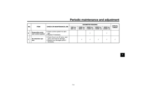 85
85 86
86 87
87 88
88 89
89 90
90 91
91 92
92 93
93 94
94 95
95 96
96 97
97 98
98 99
99 100
100 101
101 102
102 103
103 104
104 105
105 106
106 107
107 108
108 109
109 110
110 111
111 112
112 113
113 114
114 115
115 116
116 117
117 118
118 119
119 120
120 121
121 122
122 123
123 124
124 125
125 126
126 127
127 128
128 129
129 130
130 131
131 132
132 133
133 134
134 135
135